Table of Contents
Advertisement
Advertisement
Table of Contents

Related Manuals for McIntosh MC7108


Summary of Contents for McIntosh MC7108
- Page 1 MC7108 EIGHT CHANNEL POWER AMPLIFIER...
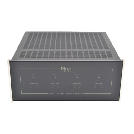
- Page 3 MC7108 EIGHT CHANNEL POWER AMPLIFIER...
- Page 4 1. Read all instructions - Read the safety and operating instructions before operating the instrument. IMPORTANT 2. Retain Instructions - Retain the safety and operating instructions for future reference. 3. Heed warnings - Adhere to warnings and operating instructions. SAFETY 4.
- Page 5 Your Mclntosh Authorized Service Agency can expedite repairs when you provide the Ser- vice Contract with the instrument for repair. SERVICE CONTRACT TABLE OF INTRODUCTION CONTENTS HOW TO INSTALL THE MC7108 FRONT PANEL DISPLAYS REAR PANEL AND HOW TO MAKE CONNECTIONS 6, 7, 8, 9, 10 CUSTOM INSTALLATION DIAGRAMS SPEAKER-AMPLIFIER CONNECTION DIAGRAMS...
- Page 6 TAKE ADVANTAGE OF 3 YEARS OF CONTRACT SERVICE FILL IN THE APPLICATION NOW. Your MC7108 Eight Channel Power Amplifier will give you many years of satisfactory perfor- mance. If you have any questions, please contact, Mclntosh Laboratory Inc. 2 Chambers Street...
- Page 7 Each of the eight channels can be operated individually, in Mono pairs or Bridged pairs into either 8 or 4 ohm loads. Each of the 8 channels of the MC7108 can produce 40 watts into a 4 ohm load. Each of the 4 bridged pairs can produce 100 watts into 4 ohm loads.
- Page 8 1. POWER (ON, OFF/REMOTE) ON position turns the MC7108 AC power on. OFF/REMOTE allows the MC7108 AC power to be turned on by a DC Logic 1 control signal from a Mclntosh Control Center or similar compatible accessory, to the POWER CONTROL IN connector.
- Page 9 25 pin 6 CHANNEL connector on a Mclntosh C39 or MX130. The six separate outputs from the Control Centers will appear at the MC7108 in the following channel alloca- tion. A power control signal to turn the MC7108 power on and off is also sent on the cable from the Control Center.
- Page 10 CONTROL IN connector from the POWER CONTROL OUT connector on compatible Mcln- REAR PANEL tosh products. The MC7108 POWER CONTROL OUT jack will feed the same AC power con- AND HOW trol signal out, delayed 0.2 seconds, to turn on and off another accessory component with TO MAKE a compatible Power Control input.
- Page 11 16. AC POWER CORD REAR PANEL Connect the MC7108 to a live 50/60HZ, 120 volt AC wall outlet or a Power Control Relay. AND HOW Do not connect the unit to an AC outlet on the rear panel of a Preamplifier or Control Center.
- Page 12 22. CHANNEL 1 AND 2 OUTPUTS REAR PANEL Stereo and Mono: Connect cables from each loudspeaker Common terminal to the Minus AND HOW (-) or Common terminals for channels 1 and 2. Connect cables from each loudspeaker positive TO MAKE terminal to the Positive ( + ) terminals for channels 1 and 2.
- Page 13 EIGHT 40 WATT CHANNELS (4 PAIRS)
- Page 14 SIX 40 WATT CHANNELS AND ONE 100 WATT BRIDGED PAIR CHANNEL...
- Page 15 FOUR 40 WATT CHANNELS AND TWO 100 WATT BRIDGED PAIR CHANNELS...
- Page 16 TWO 40 WATT CHANNELS AND THREE 100 WATT BRIDGED PAIR CHANNELS...
- Page 17 FOUR 100 WATT BRIDGED PAIR CHANNELS...
- Page 18 McINTOSH HOME THEATER SYSTEM #1 HT-3 Left HT-3 Right Surround Surround 5 CHANNEL OPERATING CONFIGURATION WITH MX118 A/V TUNER CONTROL CENTER...
- Page 19 MCINTOSH HOME THEATER SYSTEM #2 8 CHANNEL OPERATING CONFIGURATION WITH C39 or MX130 A/V CONTROL CENTER INCLUDING REMOTE AREA " B " .
- Page 20 WIDE BAND DAMPING FACTOR POWER OUTPUT, EIGHT CHANNELS SPECIFICATIONS 200 at 8 ohms 40 watts per channel, minimum sine wave continuous average power output per chan- 100 at 4 ohms nel, all channels operating into 4 ohm loads. INPUT IMPEDANCE The output RMS voltage is: 20,000 ohms 12.6V across 4 ohms...
- Page 21 RECOMMENDED VENTILATION CUTOUT CUSTOM IN MOUNTING SHELF INSTALLATION DRAWING SUPPORT SHELF MOUNTING SURFACE OUTLINE OF UNIT...
- Page 22 The numbers refer to the paragraphs on pages 6 through 9.
- Page 24 04023100...
Need help?
Do you have a question about the MC7108 and is the answer not in the manual?
Questions and answers