Table of Contents
Advertisement
Advertisement
Table of Contents

Subscribe to Our Youtube Channel
Related Manuals for G-Tec Sirius 10 kVA


Summary of Contents for G-Tec Sirius 10 kVA
- Page 1 UPS SIRIUS...
- Page 2 NTRODUCTION Thank you for choosing this product. Our company is specialized in the design, development and production of uninterruptible power supplies (UPS). The UPS described in this manual is a high-quality, meticulously-designed product, built to guarantee the best performance. This manual contains detailed instructions on how to use and install the product. For information on how to use your equipment to its full potential, this manual should be kept close at hand beside the UPS and READ BEFORE STARTING TO WORK ON IT.
-
Page 3: Table Of Contents
ONTENTS OVERVIEW Sirius RONT IEWS OF THE UPS C IEW OF THE ONNECTIONS IEW OF THE IEW OF THE ONTROL ANEL ATTERY OPTIONAL INSTALLATION TORING THE AND THE ATTERY REPARING FOR INSTALLATION RELIMINARY NFORMATION LECTROMAGNETIC OMPATIBILITY NSTALLATION NVIRONMENT FROM EMOVING THE AND THE ATTERY ALLET... -
Page 4: R.e
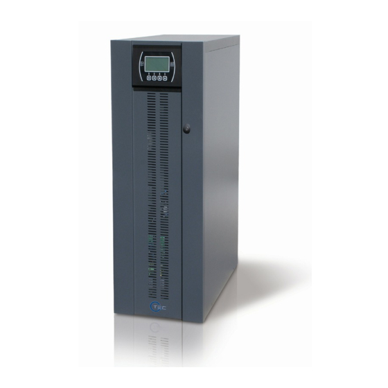
ESCRIPTION RELIMINARY PERATIONS OWERING ON FOR THE IRST OWERING ON FROM THE AINS OWERING ON FROM THE ATTERY OWERING OFF THE RAPHIC ISPLAY ISPLAY ENUS PERATING ODES (SWMB) AINTENANCE YPASS EDUNDANT UXILIARY OWER UPPLY FOR UTOMATIC YPASS ROGRAMMABLE UXILIARY OCKET POWER SHARE OWER WALK 200V... - Page 5 OVERVIEW Sirius The UPS in the Sirius 10 – 12 – 15 – 20 kVA series (VFI-SS-111 type) was designed using state-of-the-art technology so as to ensure the best performance for the user. The use of the new control boards based on multiprocessor architecture (DSL + P inside) together with high-frequency IGBT technology ensures extraordinary performance from both the input stage (absorbed current harmonic distortion ≤...
-
Page 6: Front Views Of The
RONT IEWS OF THE From left: Battery fuse holder isolator / Manual bypass Control panel with graphic display switch / Battery start button (COLD START) / 1/0 main power switch From left: Front door (to open the door, press and release Input switch / Separate bypass switch (optional) / the area marked Output switch... - Page 7 UPS C IEW OF THE ONNECTIONS Power connections: BATTERY, INPUT, SEPARATE BYPASS (optional), OUTPUT Connection for remote maintenance bypass command Connection for external Battery Box temperature probe Connection for external synchronization signal Connection for R.E.P.O. (Remote Emergency Power Off) command Slot for power relay board...
-
Page 8: Rear View Of The Ups
IEW OF THE Slots for accessory communication cards RS232 communication port Powershare sockets USB communication port (max. total 10A on two sockets) Powershare socket thermal protector Ventilation fans (manual reset) Contact holder for AS400 Area for the parallel board (optional) -
Page 9: View Of The Control
IEW OF THE ONTROL ANEL Mains power LED Battery low LED Battery power LED ECO mode LED Load on bypass LED Graphic display Stand-by / alarm LED F1, F2, F3, F4 = FUNCTION KEYS. The function of each key is indicated at the bottom of the display and varies according to the menu used. -
Page 10: Battery Box
ATTERY OPTIONAL THE BATTERY BOX IS AN OPTIONAL ACCESSORY PROVIDED FOR THIS RANGE OF UPS (SAME SIZE AND AESTHETIC DESIGN). The Battery Box contains batteries that increase the operating time of the UPS during prolonged black-outs. The number of batteries contained in it will vary according to the type of UPS to which the Battery Box is to be installed. The utmost attention must be paid to ensure that the battery voltage of the Battery Box corresponds to that supported by the UPS. -
Page 11: Preparing For Installation
INSTALLATION ALL THE OPERATIONS DESCRIBED IN THIS SECTION ARE TO BE PERFORMED EXCLUSIVELY BY QUALIFIED STAFF. The company declines all liability for damage caused by incorrect connections or operations not described in this manual. TORING THE AND THE ATTERY The storage room must respect the following conditions: Temperature: 0°... -
Page 12: Installation Environment
LECTROMAGNETIC OMPATIBILITY This Uninterruptible Power Supply (UPS) conforms to the class C2 specifications (in accordance with the provisions laid down by the EN62040-2 standard: UPS - EMC requirement). In the home environment, it may cause radio interference. The user may have to take supplementary measures. This product is designed for professional use in industrial and commercial environments. -
Page 13: Removing The Ups
FROM EMOVING THE AND THE ATTERY ALLET Cut the straps and remove the cardboard box by sliding it upwards Remove the accessory box and side blocks. NOTE 1: You will find the accessory box either inside the door of the UPS or on top of the UPS. -
Page 14: Preliminary Check Ofc
RELIMINARY HECK OF ONTENTS Having opened the package, start by checking the contents. BATTERY BOX (optional) Metal slides, Guarantee document, User manual, Metal slides, Guarantee document, Cable for connecting Cd-rom containing the UPS management software, the Battery Box to the UPS, 4 battery fuses (to be Serial connecting cable, 4 battery fuses (to be inserted in the "SWBATT"... -
Page 15: Electrical Connections
LECTRICAL ONNECTIONS WARNING: a 4-wire three-phase distribution system is required. The standard version of the UPS should be connected to a power supply line made up of 3 phases + neutral + PE (protective earth) of the TT, TN or IT type (in accordance with the IEC 60364-3 standard); the phase rotation must therefore be respected. - Page 16 UPS without any variation in neutral condition and with separate bypass input UPS with galvanic isolation and with separate bypass input UPS with galvanic isolation at output and separate bypass input Separate bypass: if the separate bypass option is present, protective devices must be present on both the main power supply line and the...
- Page 17 bypass line. Note: the neutral of the input line and that of the bypass are commoned inside the equipment, so they must refer to the same potential. If the two power supplies were different, an isolation transformer would have to be used on one of the inputs.
-
Page 18: Internal Protectived
NTERNAL ROTECTIVE EVICES OF THE The table below shows the sizes of the isolators of the UPS and the sizes of the battery fuses (SWBATT): these devices are accessible from the front of the UPS. There are also indications about the internal fuses (not accessible) protecting the input and output lines and the maximum input and rated output currents. -
Page 19: Xternal Rotective
XTERNAL ROTECTIVE EVICES AUTOMATIC CIRCUIT BREAKER As illustrated previously, the UPS is equipped with protective devices for failures both inside and at the output. When connecting the mains power supply, ensure that a type B or C (time curve) breaker is installed upstream of the UPS in accordance with the EN 60947-2 standard, as indicated in the table below: Automatic external protective devices UPS mod. -
Page 20: Cross Section Of Thec
ROSS ECTION OF THE ABLES We recommend the INPUT/OUTPUT and BATTERY cables be passed under the UPS. To determine the minimum cross section of the input and output cables, see the table below: Cross section of cables (mm2) INPUT mains / OUTPUT BATTERY (optional) -
Page 21: Connections Of The Model With Separate Bypass
ONNECTIONS OF THE MODEL WITH SEPARATE BYPASS The first wire to be connected is the protective earth wire, which is to be inserted in the terminal marked PE. During operation the UPS must be connected to the earthing system Connect the input and output cables to the terminal board as indicated in the figure below: THE INPUT AND BYPASS NEUTRALS MUST ALWAYS BE CONNECTED. -
Page 22: Connecting Ther
ONNECTING THE EMOTE AINTENANCE YPASS An additional maintenance bypass may be installed on a peripheral switchboard, for example, to enable the UPS to be replaced without interrupting the power supply to the load. It is absolutely essential to connect the "SERVICE BYPASS" terminal (see "View of the UPS Connections"... - Page 23 REMOTE MAINTENANCE BYPASS INSTALLATION DIAGRAM ON THE THREE-PHASE-THREE-PHASE WITH SEPARATE BYPASS MODEL Peripheral switchboard Internal connections of the UPS MAIN LINE switch: automatic circuit breaker, must conform to the indications given in "External Protective Devices " INPUT switch: isolator conforming to the indications given in "Internal Protective Devices of the UPS" OUTPUT switch: isolator conforming to the indications given in "Internal Protective Devices of the UPS"...
-
Page 24: Connecting Theb
ONNECTING THE ATTERY OX TO THE THE CONNECTION BETWEEN THE UPS AND THE BATTERY BOX MUST BE MADE WITH THE DEVICES POWERED OFF AND UNPLUGGED FROM THE MAINS UPS POWER-OFF PROCEDURE: Turn off all devices connected to the UPS or use the remote bypass option (if installed). Turn off the UPS following the relevant power-off procedure (see the “USE”... -
Page 25: Multiple Expansions
ULTIPLE XPANSIONS Several Battery Boxes can be connected in a cascade to ensure prolonged autonomy. The connections should be made as shown here below: WARNING (only for single UPS): No more than one UPS may be connected to each Battery Box or to more than one Battery Box connected in a cascade. -
Page 26: Use
ESCRIPTION The purpose of a UPS is to ensure a perfect power supply voltage for the devices connected to it irrespective of whether mains power is present or not. Once connected and powered, the UPS generates a sinusoidal alternating voltage with a stable amplitude and frequency, irrespective of the changes and/or variations occurring on the electricity network. -
Page 27: Preliminary Operations
RELIMINARY PERATIONS Visual check of the connection Check that all the connections have been made strictly following the indications given in the "Connections" paragraph. Check that the "1/0" button is in its "0" position (see "Front Views of the UPS" point 5). Check that all the isolators are open. -
Page 28: Powering On For The First Time
OWERING ON FOR THE IRST Set the "1/0" button to "1" and wait for a few seconds. Check that the display is turned on and the UPS enters "STAND-BY" mode. Check that no error messages appear indicating that the input cables do not respect the correct phase direction. In this case, the following operations should be performed: Turn off the UPS by setting the "1/0"... -
Page 29: Powering On From The Mains
OWERING ON FROM THE AINS Set the “1/0” switch behind the door of the UPS in its “1” position. After a few moments, the UPS is turned on, the capacitors are precharged and the "Lock / stand-by" LED blinks: The UPS is in stand-by mode. -
Page 30: Graphic Display
RAPHIC ISPLAY At the centre of the control panel there is a large graphic display, which provides, in the foreground and in real time, a detailed overview of the current status of the UPS. Directly from the control panel you can turn the UPS on/off, view the electrical values of the mains, output, battery, etc., and make the main machine settings. -
Page 31: Display Menus
ISPLAY ENUS... -
Page 32: Operating Modes
PERATING ODES The mode that guarantees maximum protection for the load is ON LINE mode, in which the energy for the load is converted twice and is generated perfectly sinusoidal at the output with the frequency and voltage set by the fine digital control of the DSP irrespective of the input (V.F.I.). -
Page 33: Rogrammable Uxiliary Ocket Power Share
EDUNDANT UXILIARY OWER UPPLY FOR UTOMATIC YPASS The UPS is equipped with a redundant auxiliary power supply that enables the UPS to run on an automatic bypass even when a failure occurs in the main auxiliary power supply. If a fault occurs in the UPS shutting off the main auxiliary power supply, the load is powered by the automatic bypass. -
Page 34: Configuring The Ups
ONFIGURING THE The table below illustrates all the possible settings at your disposal to tailor the UPS to best satisfy your needs. (Control Panel) = Indicates that the configuration can be changed not only from the configuration software but also from the control panel. (Software) = Indicates that the configuration may only be changed from the configuration software. - Page 35 FUNCTION DESCRIPTION DEFAULT POSSIBLE SETTINGS MOD. Advanced Functions Selects the allowed • ± 0.25% input frequency range Input frequency • ± 0.5% for the switch to bypass ± 5% tolerance • ± 0.75% and synchronization of • ± 1 ÷ ±10 in steps of 1% the output Selects the voltage Bypass voltage...
-
Page 36: Communication Ports
OMMUNICATION ORTS The rear panel of the UPS (see Rear View of the UPS) contains the following communication ports: Serial port available with RS232 connector and USB connector. NOTE: the use of one connector automatically excludes the other. Expansion slots for additional COMMUNICATION SLOT interface boards On the front, covered by the terminal-cover, there is another expansion slot for the power relay board (optional 250Vac, 3A, 4 programmable contacts) RS232... -
Page 37: As400 Port
AS400 P AS400 PORT PIN # NAME TYPE FUNCTION POWER Isolated auxiliary power supply, +15V±5% 80mA max Ground to which the isolated auxiliary power supply (15V) and the remote commands (Remote ON, Remote BYPASS, POWER Remote OFF) refer When pin 2 is connected to pin 15 for at least 3 seconds, the REMOTE ON INPUT #1 UPS is turned on... -
Page 38: Buzzer
UZZER The status and faults of the UPS are signalled by the buzzer, which will emit a sound modulated according to the operating conditions of the UPS. The various kinds of sound are described here below: Sound A: The signal is emitted when the UPS is turned on or off using the relevant buttons. A single beep confirms power-on, activation of the battery test, cancellation of the programmed power-off. -
Page 39: Software
OFTWARE ONITORING AND ONTROL OFTWARE The monitoring software ensures an effective and user-friendly management of the UPS, displaying all the most important items of information such as the input voltage, load applied and battery capacity. It can also automatically perform shutdown operations, send e-mails, sms and network messages when specific user- selected events occur. -
Page 40: Troubleshooting Guide
TROUBLESHOOTING GUIDE Irregular operation of the UPS is very often not an indication of a fault but is simply caused by simple problems or distractions. We therefore recommend you consult the table here below, which provides some information that will help you to solve the most common problems. -
Page 41: View Of The Ups C
PROBLEM POSSIBLE CAUSE SOLUTION THE JUMPER IS MISSING FROM THE R.E.P.O. THE DISPLAY SHOWS Assemble the jumper or check that it is inserted CONNECTOR (J13, REF. 5 - “VIEW OF THE UPS correctly. CONNECTIONS”) OR IS NOT INSERTED CORRECTLY MAINTENANCE BYPASS Open the isolator (SWMB) situated behind the door. - Page 42 PROBLEM POSSIBLE CAUSE SOLUTION PROTECTIVE DEVICE Reset the protective device upstream. WARNING: UPSTREAM FROM THE check that there is no overload or short circuit at the BYPASS LINE OPEN (ONLY IF THE DISPLAY SHOWS output of the UPS BYPASS IS SEPARATE) ONE OR MORE OF THE FOLLOWING CODES: BYPASS ISOLATOR OPEN...
- Page 43 PROBLEM POSSIBLE CAUSE SOLUTION THE DISPLAY SHOWS ONE OR MORE OF THE The batteries of the UPS should be replaced in that FOLLOWING CODES: they are no longer able to maintain the charge for a THE BATTERIES HAVE A39, A40 sufficient time to ensure the required autonomy.
-
Page 44: Status / Alarm Codes
TATUS ALARM ODES Using a sophisticated self-diagnostic system, the UPS can check and indicate on the display panel its status and any errors and/or faults that have occurred during its operation. When a problem arises, the UPS signals the event by showing the code and corresponding type of alarm on the display. - Page 45 Anomaly: “minor” problems that do not bring the UPS to a halt but affect its performance or inhibit the use of some of its functions. CODE DESCRIPTION Inverter Desynchronized External synchronism failed Overvoltage on input line of Phase1 Overvoltage on input line of Phase2 Overvoltage on input line of Phase3 Undervoltage on input line of Phase1 Undervoltage on input line of Phase2...
- Page 46 Fault: more critical problems than “Anomalies” in that, if they persist, they may bring the UPS to a halt. CODE DESCRIPTION Internal communication error Incorrect input phase direction. Input fuse of Phase1 broken or input relay blocked (will not close) Input fuse of Phase 2 broken or input relay blocked (will not close) Input fuse of Phase3 broken or input relay blocked (will not close) Input relay of Phase1 blocked (always closed)
- Page 47 Lock: indicates that the UPS is locked, a lock is normally preceded by an alarm signal and, due to their gravity, causes the inverter to be turned off and the load to be powered via the bypass line (this procedure is excluded for locks caused by serious and persistent overloads and for a lock caused by a short circuit).
-
Page 48: Technical Data
TECHNICAL DATA UPS Models 10 kVA 12 kVA 15 kVA 20 kVA Input stage Rated voltage 380-400-415 Vac Three-phase with neutral (4 wires) Rated frequency 50-60Hz Accepted tolerance for input voltage without ±20% @ 100% load activation of battery (for 400Vac) -40% +20% @50% load Accepted tolerance for input frequency without ±20%... - Page 49 UPS Models 10 kVA 12 kVA 15 kVA 20 kVA Dimensions and weight Width x Depth x Height 320 x 840 x 930 mm Tower type with wheels, display fixed to the top of the front panel. Door at the Type of structural work bottom of the front panel for access to switches and connections Weight (without batteries)
- Page 50 Battery Rated voltage per branch 240Vdc No. batteries / V 40 / 12 80 / 12 Miscellaneous Ambient temperature 0 – 40 ° C Humidity <95% non-condensing Protective devices Overcurrent – Short circuit Safety conformance EN 62040-1-1, directives 73/23/EEC and 93/68/EEC EMC conformance EN 62040-2 cl.
Need help?
Do you have a question about the Sirius 10 kVA and is the answer not in the manual?
Questions and answers