Table of Contents
Advertisement
Quick Links
Advertisement
Table of Contents

Related Manuals for IBT Technologies MB968


Summary of Contents for IBT Technologies MB968
- Page 1 MB968 8-port (Haswell + C226) Networking Motherboard USER’S MANUAL Version 1.1...
- Page 2 PS/2 is a trademark of International Business Machines Corporation. Intel is a registered trademark of Intel Corporation. Microsoft Windows is a registered trademark of Microsoft Corporation. All other product names or trademarks are properties of their respective owners. MB968 User’s Manual...
-
Page 3: Table Of Contents
Installing the Memory ............14 Setting the Jumpers ............15 Jumper Locations on MB968..........16 Jumper Settings on MB968 ..........17 JP2: Clear CMOS Setting ..........17 JP3: Clear ME Setting ............17 JP9: AT / ATX Mode Setting ..........17 JP12: BIOS Flash Security Setting ........ - Page 4 Intel® Management Engine Interface ....... 66 Intel® USB 3.0 Drivers ............. 68 Appendix..............71 A. I/O Port Address Map ........... 71 B. Interrupt Request Lines (IRQ) ........72 C. Register of the LAN Bypass Controller ......73 MB968 User’s Manual...
-
Page 5: Introduction
INSTALLATIONS Introduction Product Description ® The MB968 networking motherboard is based on the latest Intel C226 chipset. The platform supports LGA1150 Haswell processors. Four DDR3 UDIMM sockets allows up to 32GB system memory. The motherboard supports a total of eight Ethernet ports with the port 5 to port8 supporting Bypass function. -
Page 6: Specifications
#1 LED: Power (Green = Power On, Off= No Power) Front Panel #2 LED: Bypass or HDD (Jumper Select) Bypass: Green = LAN 5-6 or 7-8 Bypass, Off = LAN Normal #3 LED: Status (GPIO control, Yellow / Red) MB968 User’s Manual... - Page 7 INSTALLATIONS Two USB 3.0 + 2.0 ports at front panel One USB 2.0 for Mini PCI-e USB Ports Six USB 2.0 pin headers (pitch 2.54) Two segment hardware Bypass (Eth5 & 6; Eth7 & 8) Network ...
- Page 8 IBP165: 4-port Intel® I210-AT GbE LAN Card Cards IBP167: 8-port Intel® I350-AM4 GbE LAN Card IP331: PCI-e 1-to-1 Riser Card IP332: PCI-e Adapter Card (with 2.5” HDD Interface) IP333: PCI-e 2-to-2 Riser Card MB968 User’s Manual...
-
Page 9: Checklist
INSTALLATIONS Checklist Your MB968 package should include the items listed below. MB968 motherboard Driver DVD... -
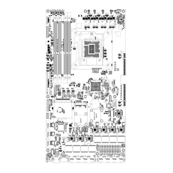
Page 10: Board Dimensions
INSTALLATIONS Board Dimensions MB968 User’s Manual... -
Page 11: Block Diagram
INSTALLATIONS Block Diagram Golden Finger 1: PCI-e x8 for front LAN module DDR3-1600 or One PCI-e x8 Haswell UDIMM x4 Golden Finger 2: One PCI-e x8 DMI 2.0 x4 SATA m-SATA x1 Pin header x6 USB 2.0 SATA Front x2 SATA III x2 USB 3.0+2.0 Marvell... -
Page 12: Installations
INSTALLATIONS Installations This section provides information on how to use the jumpers and connectors on the MB968 in order to set up a workable system. The topics covered are: Installing the CPU ................12 Installing the Memory ................13 Setting the Jumpers ................14 Jumper Locations on MB968 ............... -
Page 13: Installing The Cpu
INSTALLATIONS Installing the CPU The MB968 board supports an LGA1150 Socket (shown below) for Intel Clarkdale processors. To install the CPU, unlock first the socket by pressing the lever sideways, then lift it up to a 90-degree. Then, position the CPU above the socket such that the CPU corner aligns with the gold triangle matching the socket corner with a small triangle. -
Page 14: Installing The Memory
INSTALLATIONS Installing the Memory The MB968 board supports four DDR3 memory socket for a maximum total memory of 32GB in DDR3 DIMM memory type. Installing and Removing Memory Modules To install the DDR3 modules, locate the memory slot on the board and perform the following steps: 1. -
Page 15: Setting The Jumpers
INSTALLATIONS Setting the Jumpers Jumpers are used on MB968 to select various settings and features according to your needs and applications. Contact your supplier if you have doubts about the best configuration for your needs. The following lists the connectors on MB968 and their respective functions. -
Page 16: Jumper Locations On Mb968
INSTALLATIONS Jumper Locations on MB968 MB968 User’s Manual... -
Page 17: Jumper Settings On Mb968
INSTALLATIONS Jumper Settings on MB968 JP2: Clear CMOS Setting Setting Normal Clear CMOS JP3: Clear ME Setting Setting Normal Clear ME JP9: AT / ATX Mode Setting Setting JP12: BIOS Flash Security Setting JP12 Setting Normal For BIOS Update JP15: LED Function Selection... -
Page 18: J17, J18: Pcie Config Setting
INSTALLATIONS J17, J18: PCIE Config Setting Setting 2 x 8 for Golden Finger PCIE1 & PCIE2 1x16 for Golden Finger PCIE2 MB968 User’s Manual... -
Page 19: Connectors On Mb968
INSTALLATIONS Connectors on MB968 J2: System Function Connector ............19 J5: VGA Connectors ................21 J6, J7, J8: USB6~USB11 Ports ............21 J9: Compact Flash Socket ..............21 J10: Mini PCI- E(x1) / mSATA Socket ..........21 J11: SPI Debug Port ................21 J12: Digital IO 4IN/4OUT Connector .......... -
Page 20: J2: System Function Connector
The reset switch allows the user to reset the system without turning the main power switch off and then on again. Orientation is not required when making a connection to this header. Pin # Signal Name PM_SYSRST# MB968 User’s Manual... -
Page 21: J5: Vga Connectors
INSTALLATIONS Pins 19, 20: HDD LED This connector connects to the hard drive activity LED on control panel. This LED will flash when the HDD is being accessed. Pin # Signal Name +3.3V -HDD_LED J5: VGA Connectors Signal Name Pin # Pin # Signal Name VGA_R... -
Page 22: J12: Digital Io 4-In / 4-Out Connector
LPC_CLK J15, J16, J20: Serial Port (COM1~COM3) Signal Pin # Pin # Signal Name Name DCD# DSR# RTS# SOUT CTS# DTR# J19, J25: ATX Power Connector J21, J22, J23: Power Connector, Pitch 2.54mm Pin # Signal Name MB968 User’s Manual... -
Page 23: J24: Power Connector, Pitch 2.0Mm
INSTALLATIONS Ground Ground +12V J24: Power Connector, Pitch 2.0mm Pin # Signal Name Ground Ground +12V J27: mSATA Socket CN1, CN3: HDD Serial ATA Connector CPU_FAN1: CPU Fan Connector CPU_FAN1 is a 4-pin header for the CPU fan. The fan must be 12V (Max. 1A). Pin # Signal Name Ground... - Page 24 INSTALLATIONS A3 & C3 : Power LED Status Signal Pin # Pin # Signal Name Name Bypass or HDD SIO_GPIO33 SIO_GPIO32 +5 V JP15 Selection Power +3.3 V MB968 User’s Manual...
-
Page 25: Digital I/O Sample Configuration
INSTALLATIONS Digital I/O Sample Configuration Filename:Main.cpp //--------------------------------------------------------------------------- // THIS CODE AND INFORMATION IS PROVIDED "AS IS" WITHOUT WARRANTY OF ANY // KIND, EITHER EXPRESSED OR IMPLIED, INCLUDING BUT NOT LIMITED TO THE // IMPLIED WARRANTIES OF MERCHANTABILITY AND/OR FITNESS FOR A PARTICULAR // PURPOSE. - Page 26 |= BIT3; //set FDC_GP_EN(bit3), Set_F81865_Reg(0x2a, ucBuf); Set_F81865_LD(0x06); //switch to logic device 6 //enable the GP5 group ucBuf = Get_F81865_Reg(0x30); ucBuf |= 0x01; Set_F81865_Reg(0x30, ucBuf); Set_F81865_Reg(0xA0, 0x00); //define as input mode Set_F81865_Reg(0xA3, 0xFF); //push pull mode //--------------------------------------------------------------------------- MB968 User’s Manual...
- Page 27 INSTALLATIONS void Dio5SetOutput(unsigned char NewData) Set_F81865_LD(0x06); //switch to logic device 6 Set_F81865_Reg(0xA1, NewData); //--------------------------------------------------------------------------- unsigned char Dio5GetInput(void) unsigned char result; Set_F81865_LD(0x06); //switch to logic device 6 result = Get_F81865_Reg(0xA2); return (result); //--------------------------------------------------------------------------- void Dio5SetDirection(unsigned char NewData) //NewData : 1 for input, 0 for output Set_F81865_LD(0x06);...
- Page 28 (F81865_BASE) #define F81865_DATA_PORT (F81865_BASE+1) //--------------------------------------------------------------------------- #define F81865_REG_LD 0x07 //--------------------------------------------------------------------------- #define F81865_UNLOCK 0x87 #define F81865_LOCK 0xAA //--------------------------------------------------------------------------- unsigned int Init_F81865(void); void Set_F81865_LD( unsigned char); void Set_F81865_Reg( unsigned char, unsigned char); unsigned char Get_F81865_Reg( unsigned char); //--------------------------------------------------------------------------- #endif //__F81865_H MB968 User’s Manual...
-
Page 29: Watchdog Timer Configuration
INSTALLATIONS Watchdog Timer Configuration The WDT is used to generate a variety of output signals after a user programmable count. The WDT is suitable for use in the prevention of system lock-up, such as when software becomes trapped in a deadlock. Under these sorts of circumstances, the timer will count to zero and the selected outputs will be driven. - Page 30 // IMPLIED WARRANTIES OF MERCHANTABILITY AND/OR FITNESS FOR A PARTICULAR // PURPOSE. //--------------------------------------------------------------------------- #include "F81866.H" #include <dos.h> //--------------------------------------------------------------------------- unsigned int F81866_BASE; void Unlock_F81866 (void); void Lock_F81866 (void); //--------------------------------------------------------------------------- unsigned int Init_F81866(void) unsigned int result; unsigned char ucDid; F81866_BASE = 0x4E; result = F81866_BASE; MB968 User’s Manual...
- Page 31 INSTALLATIONS ucDid = Get_F81866_Reg(0x20); if (ucDid == 0x07) //Fintek 81866 goto Init_Finish; F81866_BASE = 0x2E; result = F81866_BASE; ucDid = Get_F81866_Reg(0x20); if (ucDid == 0x07) //Fintek 81866 goto Init_Finish; F81866_BASE = 0x00; result = F81866_BASE; Init_Finish: return (result); //--------------------------------------------------------------------------- void Unlock_F81866 (void) outportb(F81866_INDEX_PORT, F81866_UNLOCK);...
- Page 32 INSTALLATIONS #define F81866_UNLOCK 0x87 #define F81866_LOCK 0xAA //--------------------------------------------------------------------------- unsigned int Init_F81866(void); void Set_F81866_LD( unsigned char); void Set_F81866_Reg( unsigned char, unsigned char); unsigned char Get_F81866_Reg( unsigned char); //--------------------------------------------------------------------------- #endif //__F81866_H MB968 User’s Manual...
-
Page 33: Bios Setup
BIOS SETUP BIOS Setup This chapter describes the different settings available in the AMI BIOS that comes with the board. The topics covered in this chapter are as follows: BIOS Introduction ................32 BIOS Setup ..................32 Advanced Settings ................34 Chipset Settings ................... -
Page 34: Bios Introduction
These defaults have been carefully chosen by both AMI and your system manufacturer to provide the absolute maximum performance and reliability. Changing the defaults could cause the system to become unstable and crash in some cases. MB968 User’s Manual... -
Page 35: System Language
BIOS SETUP Main Settings Aptio Setup Utility – Copyright © 2012 American Megatrends, Inc. Main Advanced Chipset Boot Security Save & Exit Choose the system default BIOS Information language → ← Select Screen System Language [English] ↑↓ Select Item System Date [Fri 02/21/2014] Enter: Select System Time... -
Page 36: Advanced Settings
ESC: Exit ► PCI Express Settings PCI Latency Timer Value to be programmed into PCI Latency Timer Register. VGA Palette Snoop Enables or disables VGA Palette Registers Snooping. PERR# Generation Enables or disables PCI device to generate PERR#. MB968 User’s Manual... -
Page 37: Pci Express Settings
BIOS SETUP SERR# Generation Enables or disables PCI device to generate SERR#. PCI Express Settings Change PCI Express devices settings. PCI Express Settings Aptio Setup Utility Advanced Main Chipset Boot Security Save & Exit PCI Express Device Register Settings Relaxed Ordering [Disabled] Extended Tag [Disabled]... -
Page 38: Acpi Settings
This option may be not effective with some OS. ACPI Sleep State Select ACPI sleep state the system will enter, when the SUSPEND button is pressed. Lock Legacy Resources Enabled or Disabled Lock of Legacy Resources. S3 Video Repost Enable or disable S3 Video Repost. MB968 User’s Manual... -
Page 39: Trusted Computing
BIOS SETUP Wake up event settings Aptio Setup Utility Advanced Main Chipset Boot Security Save & Exit Wake system with Fixed Time [Disabled] Wake on Ring [Enabled] Wake on PCI PME [Enabled] → ← Select Screen Wake on PCIE Wake Event [Enabled] ↑↓... -
Page 40: Cpu Configuration
Hyper-Threading Technology) and Disabled for other OS (OS not optimized for Hyper-Threading Technology). When Disabled, only one thread per enabled core is enabled. Active Processor Cores Number of cores to enable in each processor package. Limit CPUID Maximum Disabled for Windows XP. Execute Disable Bit MB968 User’s Manual... -
Page 41: Intel Virtualization Technology
BIOS SETUP XD can prevent certain classes of malicious buffer overflow attacks when combined with a supporting OS (Windows Server 2003 SP1, Windows XP SP2, SuSE Linux 9.2, Re33dHat Enterprise 3 Update 3.) Intel Virtualization Technology When enabled, a VMM can utilize the additional hardware capabilities provided by Vanderpool Technology. -
Page 42: Thermal Configuration
Set to Disable for manual configuration. Shutdown Temperature Configuration Aptio Setup Utility Advanced Main Chipset Boot Security Save & Exit APCI Shutdown Temperature [Disabled] ACPI Shutdown Temperature Set function Disabled or 70/75/80/85/90/95/100 ℃ LAN Bypass Configuration Aptio Setup Utility MB968 User’s Manual... -
Page 43: Amt Configuration
BIOS SETUP Advanced Main Chipset Boot Security Save & Exit LAN Bypass Configuration Bypass Quick Setting [Normal] Bypass Quick Setting Set LAN Bypass to Normal, Bypass, Firewall or Custom Define Mode Normal mode: All LAN ports in NORMAL. When Watchdog monitor system hangs, software will initiates a system reboot. -
Page 44: Amt Wait Timer
User can Enable/Disable PET Events progress to receive PET events or not. Watchdog Timer Enable/Disable Watchdog Timer. Acoustic Management Configuration Aptio Setup Utility Advanced Main Chipset Boot Security Save & Exit Acoustic Management Configuration Automatic Acoustic Management [Disabled] MB968 User’s Manual... -
Page 45: Usb Configuration
BIOS SETUP → ← Select Screen ↑↓ Select Item Enter: Select Change Field F1: General Help F2: Previous Values F3: Optimized Default F4: Save ESC: Exit Smart fan function Enable or Disable. USB Configuration Aptio Setup Utility Advanced Main Chipset Boot Security Save &... -
Page 46: F81866 Super Io Configuration
KB/MS Power On [None] F2: Previous Values F3: Optimized Default F4: Save ESC: Exit Serial Port Configuration Set Parameters of Serial Ports. User can Enable/Disable the serial port and Select an optimal settings for the Super IO Device. MB968 User’s Manual... -
Page 47: Chipset Settings
BIOS SETUP F81866 H/W Monitor Aptio Setup Utility Advanced Main Chipset Boot Security Save & Exit PC Health Status Fan1 smart fan control [50 C] Fan2 smart fan control [50 C] Fan3 smart fan control [Disabled] System temperature1 +41 C System temperature2 +38 C System temperature3... -
Page 48: Wake On Lan
LAN cannot be disabled if ME is on at Sx state.) SLP_S4 Assertion Width Select a minimum assertion width of the SLP_S4# signal. Restore AC Power Loss Select AC power state when power is re-applied after a power failure. MB968 User’s Manual... -
Page 49: Pci Express Configuration
BIOS SETUP PCI Express Configuration Chipset Main Advanced Boot Security Save & Exit PCI Express Configuration PCI Express Clock Gating [Enabled] DMI Link ASPM Control [Enabled] DMI Link Extended Synch Control [Disabled] PCIE Root Port Function [Disabled] Subtractive Decode [Disabled] PCIE Port 1 is assign →... -
Page 50: Xhci Mode
ESC: Exit Azalia Control Detection of the Azalia device. Disabled = Azalia will unconditionally disabled. Enabled Azalia will be unconditionally enabled. Auto = Azalia will enabled if present, disabled otherwise. System Agent (SA) Configuration Aptio Setup Utility MB968 User’s Manual... - Page 51 BIOS SETUP Chipset Main Advanced Boot Security Save & Exit System Agent Bridge Name Haswell System Agent RC Version 1.6.2.0 VT-d Capability Supported VT-d [Enabled] → ← Select Screen CHAP Device (B0:D7:F0) [Disabled] ↑↓ Select Item Thermal Device (B0:D4:F0) [Disabled] Enter: Select Enable NB CRID [Disabled]...
-
Page 52: Graphics Configuration
Select the Video Device that will be activated during POST. This has no effect if external graphics present. Secondary booty display selection will appear based on your selection. VGA modes will be supported only on primary display. MB968 User’s Manual... -
Page 53: Memory Configuration
BIOS SETUP Memory Configuration Aptio Setup Utility Chipset Main Advanced Boot Security Save & Exit Memory Information Memory Frequency 1600 MHz Total Memory 32768 MB (DDR3) DIMM#0 8192 MB (DDR3) → ← Select Screen DIMM#1 8192 MB (DDR3) ↑↓ Select Item DIMM#2 8192 MB (DDR3) Enter: Select... -
Page 54: Quiet Boot
RT code is executed above 1MB. Option ROM Messages Set display mode for Option ROM INT19 Trap Response BIOS reaction on INT19 trapping by option ROM: IMMEDIATE: execute the trap right away. POSTPONED: execute the trap during legacy boot. MB968 User’s Manual... -
Page 55: Security Settings
BIOS SETUP Security Settings This section allows you to configure and improve your system and allows you to set up some system features according to your preference. Aptio Setup Utility Security Main Advanced Chipset Boot Save & Exit Password Description If ONLY the Administrator’s password is set, then this only limit access to Setup and is only asked for when entering Setup. -
Page 56: Save Changes And Exit
Discard Changes done so far to any of the setup options. Restore Defaults Restore/Load Defaults values for all the setup options. Save as User Defaults Save the changes done so far as User Defaults. Restore User Defaults Restore the User Defaults to all the setup options. MB968 User’s Manual... -
Page 57: Drivers Installation
DRIVERS INSTALLATION Drivers Installation This section describes the installation procedures for software and drivers. The software and drivers are included with the motherboard. If you find the items missing, please contact the vendor where you made the purchase. The contents of this section include the following: Intel Chipset Software Installation Utility ........... -
Page 58: Intel Chipset Software Installation Utility
Plug & Play INF support for Intel chipset components. Follow the instructions below to complete the installation. 1. Insert the DVD that comes with the board. Click Intel and then Intel(R) 8 Series Chipset Drivers. 2. Click Intel(R) Chipset Software Installation Utility. MB968 User’s Manual... - Page 59 DRIVERS INSTALLATION 3. When the Welcome screen to the Intel® Chipset Device Software appears, click Next to continue. 4. Click Yes to accept the software license agreement and proceed with the installation process. 5. On the Readme File Information screen, click Next to continue the installation.
-
Page 60: Vga Drivers Installation
DRIVERS INSTALLATION VGA Drivers Installation 1. Insert the DVD that comes with the board. Click Intel and then Intel(R) 8 Series Chipset Drivers. 2. Click Intel(R) Core(TM) i3/i5/i7 Graphics Driver. MB968 User’s Manual... - Page 61 DRIVERS INSTALLATION 3. When the Welcome screen appears, click Next to continue. 4. Click Yes to to agree with the license agreement and continue the installation.
- Page 62 DRIVERS INSTALLATION 5. On the screen shown below, click Install to continue. 6. Setup complete. Click Finish to restart the computer and for changes to take effect. MB968 User’s Manual...
-
Page 63: Lan Drivers Installation
DRIVERS INSTALLATION LAN Drivers Installation 1. Insert the DVD that comes with the board. Click Intel and then Intel(R) 8 Series Chipset Drivers. 2. Click Intel(R) PRO LAN Network Driver. - Page 64 DRIVERS INSTALLATION 3. Click Install Drivers and Software. 4. When the Welcome screen appears, click Next. MB968 User’s Manual...
- Page 65 DRIVERS INSTALLATION 5. Click Next to to agree with the license agreement. 6. Click the checkbox for Drivers in the Setup Options screen to select it and click Next to continue. 7. The wizard is ready to begin installation. Click Install to begin the installation.
-
Page 66: Intel® Management Engine Interface
Intel® Management Engine Interface Follow the steps below to install the Intel Management Engine. 1. Insert the DVD that comes with the board. Click Intel and then Intel(R) 8 Series Chipset Drivers and then Intel(R) AMT 9.0 Drivers. MB968 User’s Manual... - Page 67 DRIVERS INSTALLATION 2. When the Welcome screen to the InstallShield Wizard for Intel® Management Engine Components, click the checkbox for Install Intel® Control Center & click Next. 3. Click Yes to to agree with the license agreement. 4. When the Setup Progress screen appears, click Next. Then, click Finish when the setup progress has been successfully installed.
-
Page 68: Intel® Usb 3.0 Drivers
DRIVERS INSTALLATION Intel® USB 3.0 Drivers 1. Insert the DVD that comes with the board. Click Intel and then Intel(R) 8 Series Chipset Drivers. 2. Click Intel(R) USB 3.0 Drivers. MB968 User’s Manual... - Page 69 DRIVERS INSTALLATION 3. When the Welcome screen to the InstallShield Wizard for Intel® USB 3.0 eXtensible Host Controller Driver, click Next. 4. Click Yes to to agree with the license agreement and continue the installation.
- Page 70 5. On the Readme File Information screen, click Next to continue the installation of the Intel® USB 3.0 eXtensible Host Controller Driver. 6. Setup complete. Click Finish to restart the computer and for changes to take effect. MB968 User’s Manual...
-
Page 71: Appendix
DRIVERS INSTALLATION Appendix A. I/O Port Address Map Each peripheral device in the system is assigned a set of I/O port addresses which also becomes the identity of the device. The following table lists the I/O port addresses used. Address Device Description 000h - 01Fh DMA Controller #1... -
Page 72: Interrupt Request Lines (Irq)
The following table shows the IRQ used by the devices on board. Level Function IRQ0 System Timer Output IRQ1 Keyboard IRQ4 Serial Port #1 IRQ3 Serial Port #2 IRQ5 Serial Port #3 IRQ11 Serial Port #4 IRQ8 Real Time Clock IRQ14 Primary IDE IRQ15 Secondary IDE MB968 User’s Manual... -
Page 73: Register Of The Lan Bypass Controller
DRIVERS INSTALLATION C. Register of the LAN Bypass Controller To fulfill the varied requests on LAN Bypass controller, IBASE provide the smart LAN Bypass controller. User can define the Bypass function behavior when the system is power-on, power-off and WDT signal is asserted. - Page 74 1 = Enable LAN Bypass function when the Write WDT signal is asserted. CR 0x28 and CR 0x2A will be available if this bit is set to "1". 0 = Disable WDT LAN Bypass function. 2 ~ 7 Reserved MB968 User’s Manual...
- Page 75 DRIVERS INSTALLATION CR 0x28 : Watchdog (WDT) Bypass Control Register Attribute : Read / Write Reset default : 0x0000 Read / Description Port# Write Enable / Disable WDT Bypass Eth5, 6 function for each LAN port. Eth7, 8 1 = Follow the setting in "WDT Expansion Bypass Register CR 0x2A"...
- Page 76 1 = The expansion slot is Eth7, 8 populated & support LAN Bypass function Expansion Read LAN Card 0 = The expansion slot is empty Eth1, 2 or does not support LAN Bypass function Expansion LAN Card Eth3, 4 MB968 User’s Manual...
Need help?
Do you have a question about the MB968 and is the answer not in the manual?
Questions and answers