
Related Manuals for IBT Technologies MB877


Summary of Contents for IBT Technologies MB877
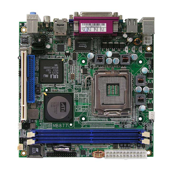
- Page 1 MB877 Socket LGA775 Pentium ® ATI RS400 Mini ITX Industrial Motherboard USER’S MANUAL Version 1.0...
- Page 2 Intel and Pentium 4 are registered trademarks of Intel Corporation. Microsoft Windows is a registered trademark of Microsoft Corporation. Winbond is a registered trademark of Winbond Electronics Corporation. All other product names or trademarks are properties of their respective owners. MB877 User’s Manual...
-
Page 3: Table Of Contents
Specifications ..............3 Board Dimensions............4 Installations .............. 5 Installing the CPU............6 ATX Power Installation...........7 Installing the Memory............7 Setting the Jumpers............8 Connectors on MB877 ..........11 Watchdog Timer Configuration ........21 BIOS Setup ..............25 Drivers Installation ..........45 Appendix ..............51 A. I/O Port address Map..........51 B. - Page 4 This page is intentionally left blank. MB877 User’s Manual...
-
Page 5: Introduction
Your MB877 Pentium 4 motherboard package should include the items listed below: Your MB877 package should include the items listed below. • The MB877 P4 Mini ITX Board • This User’s Manual • 1 CD Containing Chipset Drivers And Flash Memory Utility •... -
Page 6: Product Description
Two dual channel DDR2 memory sockets supports DDR2 400/533/667 SDRAM DIMM modules with up to 2GB in capacity. The MB877 Mini ITX motherboard supports CRT VGA interface as well as TV out. The board is designed with one Marvell 88E8052 PCI Express Gigabit LAN single controllers. -
Page 7: Specifications
USB 2.0 Support s 4 ports (D-type CN. x2 & pin header x2) Digital I/O 4 In, 4 Out Watchdog Timer Supports 256 segments (0,1,2…255. sec/min) System Voltages +5V, +12V, -12V, 5VSB, -5V, 3.3V Board Size 170 x170mm MB877 User’s Manual... -
Page 8: Board Dimensions
INSTALLATIONS Board Dimensions MB877 User’s Manual... -
Page 9: Installations
INSTALLATIONS Installations This section provides information on how to use the jumpers and connectors on the MB877 in order to set up a workable system. The topics covered are: Installing the CPU...................6 ATX Power Installation.................7 Installing the Memory................7 Setting the Jumpers ................8 Connectors on MB877.................11... -
Page 10: Installing The Cpu
INSTALLATIONS Installing the CPU The MB877 motherboard supports an LGA 775 processor socket for Intel® Pentium® 4 processors. The LGA 775 processor socket comes with a lever to secure the processor. Refer to the pictures below, from left to right, on how to place the processor into the CPU socket. -
Page 11: Atx Power Installation
Note: The power supply 5VSB voltage must be at least 2A. Installing the Memory The MB877 motherboard supports two DDR2 memory sockets for a maximum total memory of 2GB in DDR2 memory type. It supports DDR2 400/533/667 when installed with CPUs that have clock speeds of 533MHz. -
Page 12: Setting The Jumpers
INSTALLATIONS Setting the Jumpers Jumpers are used on MB877 to select various settings and features according to your needs and applications. Contact your supplier if you have doubts about the best configuration for your needs. The following lists the connectors on MB877 and their respective functions. - Page 13 INSTALLATIONS Jumper Locations on MB877 Jumper Locations on MB877..............Page JP1: COM3 RS232 +5V/+12V Power Setting..........10 JP2: COM4 RS232 +5V/+12V Power Setting..........10 JP4: Clear CMOS Contents ................10 MB877 User’s Manual...
- Page 14 +12V Short/Closed Pin 3-4 Normal Short/Closed Pin 5-6 Short/Closed JP4: Clear CMOS Contents Note: the ATX-power connector should be disconnected from the motherboard before clearing CMOS. Setting Function Pin 1-2 Normal Short/Closed Pin 2-3 Clear CMOS Short/Closed MB877 User’s Manual...
-
Page 15: Connectors On Mb877
INSTALLATIONS Connectors on MB877 The connectors on MB877 allows you to connect external devices such as keyboard, floppy disk drives, hard disk drives, printers, etc. The following table lists the connectors on MB877 and their respective functions. Connector Locations on MB877............12 ATX1: ATX Power Supply Connector..........13... - Page 16 INSTALLATIONS Connector Locations on MB877 Connectors on MB877 ..........................Page ATX1: ATX Power Supply Connector ........................13 ATX_12V1: ATX 12V Power Connector......................13 DIMM1: Channel A DDR2 Socket........................13 DIMM2: Channel B DDR2 Socket........................13 PCI1: PCI Slots ..............................13 CN1: PS/2 Keyboard and PS/2 Mouse Connectors....................14 CN2: RJ45 Connector ............................14...
- Page 17 This connector supplies the CPU operation voltage Pin # Signal Name Ground Ground +12V +12V DIMM1: Channel A DDR2 Socket DIMM1 is the first-channel DDR2 socket. DIMM2: Channel B DDR2 Socket DIMM2 is the second-channel DDR2 socket. PCI1: PCI Slots MB877 User’s Manual...
- Page 18 CN3, CN4: Serial ATA (SATA) Connectors The SATA connectors support serial ATA 150. Each connector can only use one serial ATA hard disk. CN4 is port 1 and CN3 is port 2. CN5: Line In, Line Out, Mic Connector MB877 User’s Manual...
- Page 19 TRACK WPROT RDATA SIDE J1: IrDA Connector Pin # Signal Name No connect Ir RX Ground Ir TX J2: USB Connector (USB1/USB2) J2 is a stacked USB port. Pin # Signal Name USB0 USB- USB+ USB1 Ground MB877 User’s Manual...
- Page 20 PD2, parallel data 2 Select PD3, parallel data 3 Ground PD4, parallel data 4 Ground PD5, parallel data 5 Ground PD6, parallel data 6 Ground PD7, parallel data 7 Ground ACK, acknowledge Ground Busy Ground Paper empty Ground Select MB877 User’s Manual...
- Page 21 J7 is a 30-pin header for the board’s serial ports (RS232). Signal Name Pin # Pin # Signal Name DCD2 DSR2 SIN2 RTS2 CTS2 DTR2- DCD3 DSR3 SIN3 RTS3 SOUT3 CTS3 DTR3 RI3- DCD4 DSR4 SIN4 RTS4 SOUT4 CTS4 DTR4 MB877 User’s Manual...
- Page 22 Wake On LAN will function properly only with an ATX power supply with 5VSB that has 1A. Pin # Signal Name +5VSB Ground LAN Wakeup J12: CD-In Audio Connector Pin # Signal Name CD Audio R Ground Ground CD Audio L MB877 User’s Manual...
- Page 23 JP6: Speaker Connector Pin # Signal Name Speaker CPU_FAN1: CPU Fan Power Connector Pin # Signal Name Ground +12V Rotation detection Control FAN1: System & Chassis Fan Power Connectors Pin # Signal Name Ground +12V Rotation detection MB877 User’s Manual...
- Page 24 Host data 15 Ground Protect pin DRQ0 Ground Host IOW Ground Host IOR Ground IOCHRDY Host ALE DACK0 Ground IRQ14 No connect IDE1 ADDR2ess 1 No connect ADDR2ess 0 ADDR2ess 2 Chip select 0 Chip select 1 Activity Ground MB877 User’s Manual...
-
Page 25: Watchdog Timer Configuration
;switch to LD8 mov cl, 0F5h call Read_Reg and al, NOT 08h call Write_Reg ;set count mode as second pop ax mov cl, 0F6h call Write_Reg ;set watchdog timer mov al, 01h mov cl, 30h call Write_Reg ;watchdog enabled MB877 User’s Manual... - Page 26 ; IN : None ; OUT : None ;[]=============================================== Unlock_Chip Proc Near mov dx, 4EH mov al, 87h out dx, al out dx, al Unlock_Chip Endp ;[]================================================ ; Name : Lock_Chip ; IN : None ; OUT : None MB877 User’s Manual...
- Page 27 : Read_Reg ; IN : CL - register index ; OUT : AL - Value to read ;[]=================================================== Read_Reg Proc Near mov al, cl mov dx, 4EH out dx, al inc dx al, dx Read_Reg Endp ;[]================================================ MB877 User’s Manual...
- Page 28 INSTALLATIONS This page is intentionally left blank. MB877 User’s Manual...
-
Page 29: Bios Setup
Advanced BIOS Features ..............30 Advanced Chipset Features ..............34 Integrated Peripherals ................36 Power Management Setup..............38 PNP/PCI Configurations.................41 PC Health Status..................42 Frequency/Voltage Control..............43 Load Fail-Safe Defaults ................44 Load Setup Defaults ................44 Set Password....................44 Save & Exit Setup..................44 Exit Without Saving................44 MB877 User’s Manual... -
Page 30: Bios Introduction
<PgUp> and <PgDn> keys to change entries, <F1> for help and <Esc> to quit. When you enter the Setup utility, the Main Menu screen will appear on the screen. The Main Menu allows you to select from various setup functions and exit choices. MB877 User’s Manual... - Page 31 These defaults have been carefully chosen by both Award and your system manufacturer to provide the absolute maximum performance and reliability. Changing the defaults could cause the system to become unstable and crash in some cases. MB877 User’s Manual...
-
Page 32: Standard Cmos Setup
Sun to Sat Month : 1 to 12 Date : 1 to 31 Year : 1999 to 2099 To set the date, highlight the “Date” field and use the PageUp/ PageDown or +/- keys to set the current time. MB877 User’s Manual... - Page 33 The system boot will not be halted for a disk error; it will stop for all other errors. All, But Disk/Key The system boot will not be halted for a key- board or disk error; it will stop for all others. MB877 User’s Manual...
-
Page 34: Advanced Bios Features
The options are 16Min and 64Min. Limit CPUID MaxVal The choices are: Enabled: Limits CPUID maximum value to 3 when used with older OS like Windows NT4. Disabled: Disables CPUID limit for Windows XP. MB877 User’s Manual... - Page 35 The options available include Floppy, LS/ZIP, HDD-0, SCSI,CDROM,HDD-1,HDD-2,HDD-3,USB-FDD,USB-ZIP, USB-CDROM and Disable. Boot Other Device These fields allow the system to search for an operating system from other devices other than the ones selected in the First/Second/Third Boot Device. MB877 User’s Manual...
- Page 36 Password every time you boot up. When you select Setup, the system always boots up and prompts for the Supervisor Password only when the Setup utility is called up. APIC Mode APIC stands for Advanced Programmable Interrupt Controller. The default setting is Enabled. MB877 User’s Manual...
- Page 37 If you set this feature to Disabled, the BIOS will not report the missing floppy drive to Win95/98. Small Logo (EPA) Show The EPA logo appears at the right side of the monitor screen when the system is boot up. The default setting is Enabled. MB877 User’s Manual...
-
Page 38: Advanced Chipset Features
PCI/14M/USB CLK PowerDown Disabled S.B. PCI-E Performance Enabled ULI HPET Disabled Midi Port From Super IO Game Port From Super IO Current MRC Version The default setting is 6.4. Current FSB Frequency The default setting is 200 MHz MB877 User’s Manual... - Page 39 ISA cards. This memory must be mapped into the memory space below 16 MB. The choices are Enabled and Disabled. Onboard PCI-E LAN The default setting is Enabled. Memory Timing Parameter The default setting is Auto. MB877 User’s Manual...
-
Page 40: Integrated Peripherals
ECP Mode Use DMA Phoenix - AwardBIOS CMOS Setup Utility SuperIO Device 3E8h ITEM HELP Onboard Serial Port 3 IRQ11 Menu Level Serial Port 3 Use IRQ Disabled Onboard Serial Port 4 IRQ10 Serial Port 4 Use IRQ MB877 User’s Manual... - Page 41 Extended Capabilities Port ECP+EPP Combination of ECP and EPP capabilities Normal Normal function PWRON After PWR-Fail This field sets the system power status whether on or off when power returns to the system from a power failure situation. MB877 User’s Manual...
-
Page 42: Power Management Setup
ITEM HELP IRQ[1] (Keyboard) Disabled IRQ[3] Disabled IRQ[4] Disabled IRQ[5] Disabled IRQ[6] (Floppy Disk) Disabled IRQ[7] Disabled IRQ[8] (RTC) Disabled IRQ[9] Disabled IRQ[10] Disabled IRQ[11] Enabled IRQ[12] (PS2 Mouse) Enabled IRQ[14] (Primary IDE) Disabled IRQ[15] (Secondary IDE) MB877 User’s Manual... - Page 43 When enabled, and after the set time of system inactivity, the hard disk drive will be powered down while all other devices remain active. Suspend Mode When enabled, and after the set time of system inactivity, all devices except the CPU will be shut off. MB877 User’s Manual...
- Page 44 When an I/O device wants to gain the attention of the operating system, it signals this by causing an IRQ to occur. When the operating system is ready to respond to the request, it interrupts itself and performs the service. MB877 User’s Manual...
-
Page 45: Pnp/Pci Configurations
MPEG ISA/VESA VGA card. When this field is disabled, a PCI/VGA cannot work with an MPEG ISA/VESA card. PCI IRQ Actived By The options are: Level (Default), Edge. Maximum Payload Size PCI/VGA cannot work with an MPEG ISA/VESA card. MB877 User’s Manual... -
Page 46: Pc Health Status
The values are read-only values as monitored by the system and show the PC health status. CPU/Chassis Fan Failure Warning When enabled, this field lets the system sounds a ‘ siren’ audible warning to the user that the CPU fan or chassis fan has malfunctioned. MB877 User’s Manual... -
Page 47: Frequency/Voltage Control
Phoenix - AwardBIOS CMOS Setup Utility Frequency/Voltage Control ITEM HELP Disabled Menu Level Spread Spectrum Spread Spectrum This field sets the value of the spread spectrum. The default setting is Disabled. This field is for CE testing use only MB877 User’s Manual... -
Page 48: Load Fail-Safe Defaults
Select this option to exit the Setup utility without saving the changes you have made in this session. Typing “Y” will quit the Setup utility without saving the modifications. Typing “N” will return you to Setup utility. MB877 User’s Manual... -
Page 49: Drivers Installation
Realtek AC97 Codec Audio Driver Installation .......49 Marvell 88E8052 LAN Drivers Installation ........50 IMPORTANT NOTE: After installing your Windows operating system (Windows 2000/XP), you must install first the Intel Chipset Software Installation Utility before proceeding with the drivers installation. MB877 User’s Manual... -
Page 50: Ati Rs400 Chipset Graphics Driver
2. When the Welcome screen appears, click Next to continue. 3. Click Yes to accept the software license agreement and proceed with the installation process. After the installation, Setup will be complete. Start the system when prompted and for changes to take effect. MB877 User’s Manual... -
Page 51: Uli M1573 Integrated Driver
Follow the instructions below to complete the installation under Windows 2000/XP. 1. Insert the CD that comes with the board and the screen below would appear. Click ULI M1573 Integrated Driver. 2. Click Finish to restart the computer and for changes to take effect. MB877 User’s Manual... -
Page 52: Uli M5287 Sata/Raid Disk Installation
During the installation of the operating system, there will be a screen that prompts the user to press <F6> in order to install the SCSI or RAID controller drivers. Press <F6> to start RAID drivers installation. Follow the installation instructions as indicated to finish the installation process. MB877 User’s Manual... -
Page 53: Realtek Ac97 Codec Audio Driver Installation
1. Insert the CD that comes with the board and the screen below would appear. Click Realtek AC97 Codec Audio Drivers to start the drivers installation. 2. Click Finish to restart the computer and for changes to take effect. MB877 User’s Manual... -
Page 54: Marvell 88E8052 Lan Drivers Installation
1. Insert the CD that comes with the board. In the initial screen, click on LAN Card on the left side. 2. When the Welcome screen appears, click Next to start the drivers installation. Click Finish after successfully installing the Marevell Miniport Driver. MB877 User’s Manual... -
Page 55: Appendix
Parallel Port #1(LPT1) 360h - 36Fh Network Ports 3B0h - 3BFh Monochrome & Printer adapter 3C0h - 3CFh EGA adapter 3D0h - 3DFh CGA adapter 3F0h - 3F7h Floppy Disk Controller 3F8h - 3FFh Serial Port #1(COM1) MB877 User’s Manual... -
Page 56: Interrupt Request Lines (Irq)
Serial Port #2 IRQ4 Serial Port #1 IRQ5 Reserved IRQ6 Floppy Disk Controller IRQ7 Parallel Port #1 IRQ8 Real Time Clock IRQ9 Reserved IRQ10 Reserved IRQ11 Reserved IRQ12 PS/2 Mouse IRQ13 80287 IRQ14 Primary IDE IRQ15 Secondary IDE MB877 User’s Manual... -
Page 57: Digital I/O Sample Code
#define W627_IOBASE 0x4E //============================================================== #define W627HF_INDEX_PORT (W627_IOBASE+0) #define W627HF_DATA_PORT (W627_IOBASE+1) //============================================================== #define W627HF_REG_LD 0x07 //============================================================== #define W627HF_UNLOCK 0x87 #define W627HF_LOCK 0xAA //============================================================== void Set_W627HF_LD(unsigned char); void Set_W627HF_Reg(unsigned char, unsigned char); unsigned char Get_W627HF_Reg(unsigned char); //============================================================== #endif //__W627HF_H MB877 User’s Manual... - Page 58 W627HF_REG_LD); outportb(W627HF_DATA_PORT, LD); Lock_W627HF(); //===================================================================== void Set_W627HF_Reg(unsigned char REG, unsigned char DATA) Unlock_W627HF(); outportb(W627HF_INDEX_PORT, REG); outportb(W627HF_DATA_PORT, DATA); Lock_W627HF(); //===================================================================== unsigned char Get_W627HF_Reg(unsigned char REG) unsigned char Result; Unlock_W627HF(); outportb(W627HF_INDEX_PORT, REG); Result = inportb(W627HF_DATA_PORT); Lock_W627HF(); return Result; //===================================================================== MB877 User’s Manual...
- Page 59 Set_W627HF_Reg(0xF1, ((ucDO & 0x0F) << 4)); ucBuf = Get_W627HF_Reg(0xF1) & 0x0F; if (ucBuf != ucDI) ucDI = ucBuf; printf("Digital I/O Input Changed. Current Data is 0x%X\n",ucDI); if (kbhit()) getch(); break; delay(500); return 0; //===================================================================== void ClrKbBuf(void) while(kbhit()) getch(); //--------------------------------------------------------------------------- MB877 User’s Manual...
- Page 60 APPENDIX This page is intentionally left blank. MB877 User’s Manual...
Need help?
Do you have a question about the MB877 and is the answer not in the manual?
Questions and answers