Mitsubishi Electric WD8200U User Manual
Hide thumbs
Also See for WD8200U:
- User manual (76 pages) ,
- Brochure & specs (2 pages) ,
- Overview (4 pages)
Table of Contents
Advertisement
Quick Links
Advertisement
Table of Contents

Related Manuals for Mitsubishi Electric WD8200U


Summary of Contents for Mitsubishi Electric WD8200U
- Page 1 Инструкция Mitsubishi Electric WD8200U Перейти в карточку товара 8 800 775 98 98...
- Page 2 DLP™ PROJECTOR MODEL WD8200U WD8200LU User Manual WD8200 This User Manual is important to you. Please read it before using your projector.
- Page 3 CAUTION RISK OF ELECTRIC SHOCK DO NOT OPEN : TO REDUCE THE RISK OF ELECTRIC CAUTION SHOCK, DO NOT REMOVE COVER (OR BACK) NO USER-SERVICEABLE PARTS INSIDE REFER SERVICING TO QUALIFIED SERVICE PERSONNEL. The lightning flash with arrowhead symbol within an equilateral triangle is intended to alert the user to the presence of uninsulated “dangerous voltage”...
-
Page 4: Table Of Contents
Contents Important safeguards ........................4 Preparing your projector ........................6 Using the remote control ........................9 Setting up your projector .........................11 Viewing computer images .......................19 Viewing video images ........................26 Menu operation ..........................31 Adjusting projected images ......................42 Initial network settings ........................49 Lamp relay ............................53 Advanced features ..........................55 Replacing the lamp .........................62 Maintenance ............................64... -
Page 5: Important Safeguards
Important safeguards Please read all these instructions regarding your 10. Power sources projector and retain them for future reference. Follow This projector should be operated only from the all warnings and instructions marked on the projector. type of power source indicated on the marking label. - Page 6 Important safeguards (continued) WARNING: Do not block the air inlet and outlet grilles. If they are blocked, heat may be generated inside the Unplug immediately if there is something projector, causing deterioration in the projector quality wrong with your projector. and fire.
-
Page 7: Preparing Your Projector
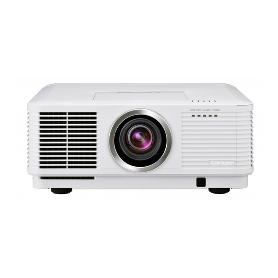
Preparing your projector Checking accessories The following accessories are provided with this projector. Check to be sure that all of the accessories are packed in the package. Cables Power supply parts Mini D-SUB D-SUB 15-pin 9-pin Mini D-SUB D-SUB 15-pin 9-pin RS-232C cable RGB cable for PC... - Page 8 Preparing your projector (continued) Overview 1 Indicators 2 Air inlet grille/Filter cover 3 Air outlet grille 4 Lens 5 Remote control sensor (front) 6 Mitsubishi logo plate position (Put the plate according to the installation orientation.) 7 Air inlet grille 8 Control area 9 Terminal panel 10 Remote control sensor (rear)
- Page 9 Preparing your projector (continued) Indicators Bottom side 1 Lock bar (SECURITY ANCHOR) the projector. 2 Adjustment feet 1 FILTER indicator 2 STATUS indicator 3 LAMP 2 indicator 4 LAMP 1 indicator 5 POWER indicator Remote control 1 Indicator 2 POWER button 3 COMPUTER 1, 2 buttons 4 MENU button 5 BLANK button...
-
Page 10: Using The Remote Control
Using the remote control Operational range of the remote control Rear of projector Front of projector About 30° About 30° About 30° About 30° Operate the remote control within a distance of 30 m (98.4 feet) from the projector, pointing the light beam at the remote control photo-sensor (front or rear) of the projector. -
Page 11: Setting The Id Number Of The Remote Control
Using the remote control (continued) XX: Shows the ID number of the projector. Setting the ID number of the remote (When the PROJECTOR ID is “ALL,” “ALL” control is displayed.) You can control multiple projectors collectively or YY: Shows the current CONTROLLER ID. (When individually using one remote control by setting the ID the CONTROLLER ID is “ALL,”... -
Page 12: Setting Up Your Projector
Screen size and projection distance Refer to the following table to determine the screen size and projection distance. (For WD8200U only. For WD8200LU, see page 75.) Front projection... -
Page 13: Adjusting The Position Of The Projected Image
Setting up your projector (continued) Setup adjustment SHIFT menu is displayed, the shift mode can be switched between FAST and STEP. When FAST How to turn on the projector is selected, the lens shifts in a large amount with When you have to turn on the projector for setup button, and it shifts in a small adjustment, see the following pages: amount when STEP is selected. -
Page 14: Setting Image Reverse
Setting up your projector (continued) Setting the projector posture Setting HIGH ALTITUDE MODE You can select the posture of the projector. Set COOLING CONDITION in the INSTALLATION 1 menu 1 menu according to the altitude at which you use according to the posture. the projector. -
Page 15: Correcting Skewed Or Distorted Image
Setting up your projector (continued) Correcting skewed or distorted image Adjustment using the KEYSTONE mode: When the screen and the projector are not placed For the best projection, project images on a flat screen perpendicularly to each other, projected images installed at 90 degrees to the floor. - Page 16 Setting up your projector (continued) LOWER RIGHT, LOWER LEFT, UPPER RIGHT, or performed, the displayed image may be distorted. UPPER LEFT menu You can adjust the horizontal or vertical position of the projector and the screen, a perfect rectangular selected corner. image and the proper aspect ratio may not be Example: Adjustment of the upper left corner position obtained.
- Page 17 Setting up your projector (continued) Adjusting the origin to the horizontal arc Adjustment using the CURVED mode To adjust images projected on a curved surface, press (or the ARC is adjusted in the direction) the ENTER/GEOMETRY button on the projector or the GEOMETRY button on the remote control to display the CURVED mode, and then press the button to correct the distortion.
- Page 18 Setting up your projector (continued) the ARC is adjusted in the direction) Press the button. Press the Press the button. button. Press the button. When you press the button in the RESET mode, the distortion correction is reset. Important: the resolution decreases. In addition, stripes may appear or straight lines may bend in images with complicated patterns.
-
Page 19: Rear Projection
Setting up your projector (continued) Front projection, ceiling mounting Rear projection For ceiling mounting, you need the ceiling mount Ask a specialist for installation. For details, consult kit designed for this projector. Ask a specialist for your dealer. installation. For details, consult your dealer. damage caused by use of any non-recommended ceiling mount kit or installation of the ceiling mount kit in an improper location. -
Page 20: Viewing Computer Images
Viewing computer images A. Connecting the projector to a computer Preparation: Computer For analog connection: (For using the COMPUTER/COMPONENT VIDEO IN-1 terminal.) COMPUTER/ 1. Connect one end of the supplied RGB cable to the COMPONENT COMPUTER/COMPONENT VIDEO IN-1 terminal of the VIDEO IN-1 projector. - Page 21 Viewing computer images (continued) B. Plugging the power cord breaker to supply the power to the projector. If you do not have such outlet, ask your dealer to install it. 1. Plug the attached power cord into the power cord inlet of this projector.
- Page 22 Viewing computer images (continued) C. Installing the terminal cover This projector includes a terminal cover. If necessary, install the terminal cover to the projector. 1. Fit two hooks of the terminal cover into the projector. 2. Tighten the attachment screws (a) irmly. You can use the buttons on the operation panel by removing the door of the terminal cover.
- Page 23 Viewing computer images (continued) D. Projecting images Preparation: POWER button POWER button LAMP 2 indicator POWER indicator COMPUTER 1, 2 buttons LAMP 1 indicator buttons DVI-D(HDCP) button ENTER button COMPUTER/DVI-D button buttons ENTER button LENS SHIFT button ZOOM/FOCUS button ZOOM/FOCUS button LENS SHIFT button Main power switch 1.
- Page 24 Viewing computer images (continued) 9. Press the ZOOM/FOCUS button to display the ZOOM/FOCUS menu. 10. Adjust with the button to get an approximate size. switched between FAST and STEP. When FAST is selected, the speed of zoom controlled by the button becomes fast, and it becomes slow when STEP is selected.
- Page 25 Viewing computer images (continued) Blanking the screen temporarily (BLANK) The video signal is temporarily muted when the BLANK button is pressed. The screen turns black. You will hear a mechanical shutter sound inside the projector. To cancel muting, press the BLANK button again. AUTO POSITION button When the image supplied from the computer is displaced, carry out the following procedure.
-
Page 26: Setting The Aspect Ratio
Viewing computer images (continued) Setting the aspect ratio You can change the aspect ratio of the input video signal (or the ratio of width to height of the image). Change the setting according to the type of the screen to be used or your preference. How to change the settings: With the remote control: 1. -
Page 27: Viewing Video Images
Viewing video images A. Connecting the projector to video equipment Preparation: Make sure that the power of the projector and that of the video equipment are turned off. Connecting to a video player, etc. 1. Connect one end of a commercially available BNC cable to Video player, or the like BNC cable (option) the VIDEO IN terminal of the projector. - Page 28 Viewing video images (continued) Projector + DVD player or HDTV decoder Some DVD players have an output connector for 3-line itting (Y, C ). When connecting such DVD player with this projector, use the COMPUTER/COMPONENT VIDEO IN-2 terminals. DVD player or HDTV decoder BNC-RCA connector (option) COMPUTER/COMPONENT VIDEO IN-2...
- Page 29 Viewing video images (continued) Connection (for video equipment having a DVI-D terminal) Equipment having a DVI-D terminal To DVI-D terminal COMPUTER/COMPONENT VIDEO DVI-D IN (HDCP) DVI cable (option) When you connect this projector and a digital device (such as a DVD player) via the HDMI IN or COMPUTER/ COMPONENT VIDEO DVI-D IN (HDCP) terminal, black color may appear dark and deep, depending on the type of the connected device.
- Page 30 Viewing video images (continued) D. Projecting images Preparation: POWER button POWER button LAMP 2 indicator HDMI button POWER indicator COMPUTER 1, 2 buttons LAMP 1 indicator VIDEO button buttons S-VIDEO button DVI-D(HDCP) button COMPUTER/DVI-D button ENTER button VIDEO/HDMI button ENTER button buttons LENS SHIFT button ZOOM/FOCUS button...
- Page 31 Viewing video images (continued) 7. Adjust the position of the projector to keep an appropriate projection distance with which images are projected in their speciied sizes. 8. Adjust the position of the projector so that the projector and the screen are perpendicular to each other. (See page 11.) 14.) 9.
-
Page 32: Menu Operation
Menu operation You can make various settings using the displayed menus. Following 8 menus are displayed. IMAGE menu (page 33) INSTALLATION 1 menu (page 34) INSTALLATION 2 menu (page 35) opt. opt. opt. INSTALLATION 1 IMAGE INSTALLATION 2 COLOR ENHANCER LAMP MODE AUTO STANDARD... -
Page 33: How To Set The Menus
Menu operation (continued) How to set the menus 1. Press the MENU button. Selectable menus are displayed by icons. (The menu icon being selected is displayed on a blue background.) opt. IMAGE The name of the menu being selected is displayed. 2. - Page 34 Menu operation (continued) IMAGE menu opt. opt. IMAGE IMAGE ADVANCED MENU COLOR ENHANCER AUTO SUPER RESOLUTION NOISE REDUCTION CONTRAST INPUT LEVEL BRIGHTNESS CLOSED CAPTION COMPUTER COLOR TEMP. STANDARD COLOR TINT SHARPNESS ADVANCED MENU ENTER ITEM SETTING FUNCTION COLOR ENHANCER AUTO Select to optimize the settings automatically depending on the input signal.
- Page 35 Menu operation (continued) INSTALLATION 1 menu opt. opt. INSTALLATION 1 INSTALLATION 1 LENS LOCK LAMP MODE STANDARD LAMP SELECT ZOOM/FOCUS LOCK DUAL LENS SHIFT LOCK LAMP RELAY 1H/24H STANDBY MODE LENS SHIFT RESET IMAGE REVERSE HIGH ALTITUDE MODE STANDARD COOLING CONDITION 0°...
- Page 36 Menu operation (continued) INSTALLATION 2 menu opt. INSTALLATION 2 AUTO POWER ON AUTO POWER OFF 5min IMAGE CAPTURE SETUP SPLASH SCREEN BACK COLOR BLUE DVI LONG CABLE AUTO REMOTE 1 MODE ENTER FILTER MENU ENTER ITEM SETTING FUNCTION AUTO POWER ON ON / OFF When ON is chosen, the projector is automatically turn on when the power cord is plugged in the wall outlet.
- Page 37 Menu operation (continued) MULTI-SCREEN menu opt. MULTI-SCREEN EDGE BLENDING SETTING EDGE ADJUST COLOR MATCHING MANUAL SETTING MEASURE MEASURED DATA ITEM SETTING FUNCTION EDGE BLENDING Select when using the projector alone. Select when using the projector to conigure the multi-screen consisting of multiple projectors.
- Page 38 Menu operation (continued) FEATURE menu opt. opt. FEATURE FEATURE ASPECT NORMAL (FULL) ADVANCED MENU PROJECTOR ID AUTO VIDEO SIGNAL SETUP GROUP ID AUTO PASSWORD FUNCTION DISPLAY INPUT SCART INPUT MENU POSITION LAMP WARNING STANDARD HIDE OSD CINEMA MODE AUTO LAMP 1 TIME RESET LANGUAGE English ADVANCED MENU...
- Page 39 Menu operation (continued) FEATURE menu (continued) ITEM SETTING FUNCTION SCART INPUT ON / OFF Choose ON when connecting the projector with a device equipped with the SCART terminal that can output RGB signal. SCART terminal is used mainly in Europe. Choose OFF normally. (Available only for the input signal from the COMPUTER/COMPONENT VIDEO IN-1 terminal.) LAMP WARNING...
- Page 40 Menu operation (continued) SIGNAL menu opt. opt. opt. SIGNAL SIGNAL SIGNAL RESOLUTION (MEMORIZE) USER MEMORY CALL AUTO RESOLUTION VERTICAL 60.00 Hz 1024 x 768 CLAMP POSITION (MEMORIZE FREQUENCY HORIZONTAL HORIZ. POSITION 48.36 KHz CLAMP WIDTH FREQUENCY 1024 VERT. POSITION HORIZ. PIXELS VERT.
- Page 41 Menu operation (continued) NETWORK menu opt. opt. NETWORK NETWORK IP CONFIG PROJECTOR NAME NETWORK PASSWORD DHCP ENTER IP ADDRESS 0. 0. 0. 0 IP CONFIG ENTER NETWORK CERTIFICATION SUBNET MASK 0. 0. 0. 0 DEFAULT GATEWAY CONTROL SYSTEM 0. 0. 0. 0 STANDARD MAC ADDRESS NETWORK RESET...
- Page 42 Menu operation (continued) INFORMATION menu opt. INFORMATION LAMP 1 TIME (LOW) **** LAMP 2 TIME (LOW) **** NEXT LAMP RELAY FILTER TIME TIMES ***** **** SERIAL NUMBER ******** INPUT COMPUTER1 RESOLUTION 1024 x 768 VERTICAL 60.00 Hz FREQUENCY HORIZONTAL 48.36 kHz FREQUENCY SYNC.
-
Page 43: Adjusting Projected Images
Adjusting projected images To adjust the brightness (CONTRAST and BRIGHTNESS): You can make adjustments for the brightness of the projected image using the menu. (See page 32 for menu setting.) 1. Display the IMAGE menu. 2. Select CONTRAST or BRIGHTNESS by pressing the button. -
Page 44: Color Enhancer
Adjusting projected images (continued) To cancel the menu: 7. Press the MENU button. To enable the stored color temperature: 1. Set COLOR TEMP. to USER in the IMAGE menu. About color temperature Color temperature is a way to show the differences in white. White of which temperature is low appears reddish. When the color temperature rises, white appears bluish. - Page 45 Adjusting projected images (continued) Adjusting the fineness of the image (SUPER RESOLUTION): You can adjust the ineness of the image using the menu. (See page 32 for menu setting.) With the IMAGE menu: 1. Display the IMAGE menu. SUPER RESOLUTION 2.
-
Page 46: How To Adjust The Computer Image
Adjusting projected images (continued) How to adjust the computer image This projector automatically selects a proper signal format according to the type of video signal supplied from the computer. However, video signals from the computer may not be projected correctly depending on the types of the computer and images to be projected. - Page 47 Adjusting projected images (continued) How to adjust the image supplied from the computer using the menu: Carry out the following procedures according to the symptoms. Wide strips appear. ��������������� Adjust TRACKING in the SIGNAL menu. The projected image flickers. The projected image is blurred........Adjust FINE SYNC. in the SIGNAL menu. The projected image is displaced horizontally.
- Page 48 Adjusting projected images (continued) 11. Press the ENTER button. Adjusting the image displayed on SETTING - BLACK LEVEL the multi-screen INTERLOCKED You can conigure a multi-screen display using multiple projectors. GREEN You can make the joints of the images displayed on BLUE the projectors unnoticeable and adjust the differences 12.
-
Page 49: Adjusting The Color Variations
Adjusting projected images (continued) 7. Select an item you want to set by pressing the Adjusting the color variations button. You can adjust the variations in the colors of the images displayed on multiple projectors using the COLOR. menu settings. (See page 32 for menu setting.) 8. -
Page 50: Initial Network Settings
Initial network settings You can set the network of the projector using the menu. selecting OK or CANCEL. opt. Network Password Settings NETWORK (See page 32 for menu setting.) PROJECTOR NAME NETWORK PASSWORD ENTER 1. Display the NETWORK menu. IP CONFIG ENTER 2. - Page 51 Initial network settings (continued) 6. Enter the NEW NETWORK PASSWORD and Setting or Clearing DHCP CONFIRM NETWORK PASSWORD. 1. Display the IP CONFIG menu. 2. Press the button to select DHCP. including alphabets (capital/small) or numeric characters. DHCP key: ..... Shifting the position of enter cursor to the left for each 3.
- Page 52 Initial network settings (continued) 6. When selecting OK, the setting is completed as the IP ADDRESS stored. However, when selecting setting change dialog is displayed. After the CANCEL, the setting is completed without storing. dialog disappears, the NETWORK menu is displayed.
- Page 53 Initial network settings (continued) Initialization of Network Settings Glossary For more detail of the glossary below, refer to the (See page 32 for menu setting.) technical book that is commercially available. 1. Display the NETWORK menu. Term Description 2. Press the button to select NETWORK Abbreviation for Dynamic Host RESET.
-
Page 54: Lamp Relay
Lamp relay Using the lamp relay function, you can project images 1H/24H continuously. The lamp relay function automatically rests or switches the lamps. The lamp relay is NEXT LAMP RELAY performed when LAMP SELECT in the INSTALLATION 2 3 H 1 menu is set to DUAL or SINGLE. - Page 55 Lamp relay (continued) 1 WEEK selection, or during the lamp relay operation, you cannot change the setting of LAMP SELECT and NEXT LAMP RELAY LAMP RELAY. 7 D 0 0 H deteriorate earlier unless they are turned off for 1 CLEAR hour per week.
-
Page 56: Advanced Features
Advanced features Changing the image displayed at the frame is captured. startup You can display your desired image as the startup mode automatically. screen (or splash screen). By setting the menu, you can use such image instead of the background image that is displayed when no video signal is supplied. -
Page 57: Password Function
Advanced features (continued) 7. Press the ENTER button. Password function To cancel the procedure, press the MENU This projector is equipped with the password function button. that is designed for prevention of wrong operation by 8. Enter the password again for conirmation using the children and restriction on operation by other than same steps. -
Page 58: Magnifying The Displayed Image
Advanced features (continued) Split Magnifying the displayed image You can split the screen in two and display a computer By pressing the MAGNIFY button on the remote control, you can magnify the image to view the details. image on the left screen and a video image on the right screen. -
Page 59: Supervising And Controlling By Computer
Advanced features (continued) Supervising and controlling by computer Important: You can supervise and control the projector’s in the NETWORK menu, the web control for operation using a personal computer via a LAN Crestron is enabled. For such control, Adobe Flash network. - Page 60 INF1? Inquiry about the manufacturer name “MITSUBISHI” is returned. INF2? Inquiry about the model name “WD8200U” or “WD8200LU” is returned. INF0? Inquiry about other information No other information is available. No parameter is returned. CLSS? Inquiry about the class information “1”...
-
Page 61: Monitoring And Control Using Serial Terminal
Advanced features (continued) Monitoring and control using SERIAL terminal Using the SERIAL terminal, you can monitor and control multiple projectors collectively or individually. For details, contact your dealer. To RS-232C terminal RS-232C cable RS-232C cable To SERIAL To SERIAL To SERIAL To SERIAL To SERIAL See also the instruction manuals of the devices to... - Page 62 Advanced features (continued) Control by a control panel, etc. When installing the projector in a place where the remote control signals cannot reach the projector, you can control the projector using a control panel or other device connected to the REMOTE 1 IN terminal. External contact Remote control control...
-
Page 63: Replacing The Lamp
Replacing the lamp because of an impact, scratch, or deterioration This projector is equipped with 2 lamps to project through use. The period of time until explosion or images. This lamp is a consumable. It may burn out permanent failure to illuminate varies considerably or its brightness may decrease during use. - Page 64 Replacing the lamp (continued) 3. Loosen three screws (c) that are securing the lamp Reset of the lamp operation time box to be removed using a Philips screwdriver. Reset the lamp operating time of the newly installed lamp. LAMP 2 LAMP 1 You can reset the lamp operation time using the menu.
-
Page 65: Maintenance
Replacing the lamp (continued) When removing the lamp from the ceiling-mounted projector When removing the lamp from the ceiling-mounted projector, use the lamp replacement tray packed with the projector or option lamp to prevent glass fragments from scattering. 1. Follow steps 1 to 4 on pages 62 and 63. 2. -
Page 66: Automatic Cleaning Filter
Automatic cleaning filter This projector is equipped with an automatic cleaning 7. Move the key cursor using the direction buttons to ilter. The burdensome ilter cleaning is automatically select the number you want to enter and then press carried out. the ENTER button. - Page 67 Automatic cleaning filter (continued) 4. Attach the dust box to the automatic cleaning ilter. How to clean the automatic cleaning filter Check the amount of dust through the dust check window of the ilter cover and clean it, if necessary. Before cleaning the ilter, be sure to turn off the main power switch of the projector and unplug the power cord from the outlet.
-
Page 68: Troubleshooting
Troubleshooting Before asking for repair of the projector, check the following. If the symptom persists, stop using the projector, be sure to unplug the power plug, and then contact your dealer. No image appears on the screen. Problem Solution Power can not be turned on. - Page 69 Troubleshooting (continued) No image appears on the screen. (continued) Problem Solution The screen for entering the password enable the password lock. appears. Enter the password or contact the person in charge of management of the projector. (See page 56.) “NO SIGNAL” is displayed.
- Page 70 Troubleshooting (continued) Images are not displayed correctly. (continued) Problem Solution Tint in projected images is incorrect. Different color tint. When comparing images projected by two projectors, tints in the displayed images may be different because of variation between their optical components. This is not a malfunction. television or PC monitor, tints in the displayed images may be different because of difference in the range of color reproducibility.
- Page 71 Troubleshooting (continued) Others (continued) Problem Solution Abnormal sound is heard. occasions. Such symptom is not a malfunction. FOCUS/ZOOM (See page 34.) doesn’t work. Lens shift doesn’t work. If the following problem occurs after the lamp is replaced, check the following first. Problem Solution The projector does not...
-
Page 72: Indicators
Indicators This projector has 5 indicators, each of which shows the operation condition of the projector. The following offer solutions to possible problems. If these problems persist, turn the projector off and consult your dealer. POWER indicator FILTER indicator LAMP 1 indicator STATUS indicator LAMP 2 indicator POWER, STATUS, and FILTER: The current condition is indicated. -
Page 73: Specifications
Option color-wheel: CW-FC2 *1: For WD8200U only. For WD8200LU, see page 75. *2: For WD8200U only. The weight of WD8200LU is obtained by subtracting the weight of the lens part of WD8200U from the above values. *3: For WD8200U only. Important: option color-wheel. - Page 74 Specifications (continued) Specification of RGB signals in each computer mode of the projector Signal mode Resolution Horizontal Vertical frequency Normal mode Real mode (H x V) frequency (kHz) (Hz) (H x V) (H x V) TV60, 480i (525i) 720 x 480 15.73 59.94 1066 x 800...
- Page 75 Specifications (continued) Specification of RGB signals in each computer mode of the projector (continued) video devices having 4 lines (R, G, B, CS*) or having 5 lines (R, G, B, H, V). Important: * : Composite Sync Some computers aren’t compatible with the projector.
- Page 76 Specifications (continued) Specification of the attached lens (for WD8200LU) With tele throw zoom lens (OL-XD2000TZ) F No. F2.2 - 2.7 Focal distance f = 40.7 - 65.1 mm Zoom/focus Electric drive Screen size (16:10) Projection distance (L) Lens shift height Lens shift Center of the width...
- Page 77 MITSUBISHI ELECTRIC CORPORATION 1 Zusho Baba, Nagaokakyo-City, Kyoto Japan...
- Page 78 Mitsubishi Electric WD8200U Описание Характеристики...
Need help?
Do you have a question about the WD8200U and is the answer not in the manual?
Questions and answers