
Subscribe to Our Youtube Channel
Related Manuals for Sutron TesiMod TP22

Summary of Contents for Sutron TesiMod TP22
- Page 1 User Manual TesiMod Touch Panel TP22 Part Number: 80 860.545 Version: Date: 09.12.2005 Valid for: TP22EM TP22ES TP22ET...
- Page 2 Version Date Modifications 28.02.2002 First Edition 30.07.2002 Chapter „identification“ and „touch“ new, table „user mode switch“ and chapter „contrast- / brightness setting“ repro- cessed, technical data reprocessed. 31.10.2002 Chapter "identification" reprocessed. 6.11.2002 Chapter "changing the battery" and technical data of the keyboard and touch reprocessed.
-
Page 3: Table Of Contents
Overall Table of Contents Overall Table of Contents Important Notes ....................... 1-1 Symbols ....................1-1 1.1.1 General Symbols ................. 1-1 1.1.2 Specific Symbols ................. 1-1 Safety Notes ..................... 1-2 Intended Use..................... 1-2 Target Group..................... 1-2 Installation and Commissioning ................2-1 Unpacking the Device ................ - Page 4 Overall Table of Contents 4.1.2.2 Termination......................... 4-5 4.1.3 RS232 (X3-SER1)................4-6 4.1.3.1 Pin Assignment......................4-6 4.1.3.2 Termination......................... 4-6 4.1.4 RS232 (X3-SER2)................4-7 4.1.4.1 Pin Assignment......................4-7 Field Bus Interfaces .................. 4-8 4.2.1 CAN (X2.1/X2.2) .................. 4-8 4.2.1.1 Pin Assignment......................4-9 4.2.1.2 Cable ........................
- Page 5 Overall Table of Contents Ordering Data ......................7-1 Index ........................A-1...
- Page 6 Overall Table of Contents 1-iv...
-
Page 7: Important Notes
Important Notes 1 Important Notes Symbols The symbols in this manual are used to draw your attention on notes and dangers. 1.1.1 General Symbols Danger This symbol is used to refer to instructions which, if ignored or not carefully followed could result in personal injury. -
Page 8: Safety Notes
Important Notes Safety Notes – Read this manual carefully before using the operating device. Keep this manual in a place where it is always accessible to all users. – Proper transportation, handling and storage, placement and installation of this product are prerequisites for its subsequent flawless and safe operation. –... -
Page 9: Installation And Commissioning
Installation and Commissioning 2 Installation and Commissioning Unpacking the Device Unpack all parts carefully and check the contents for any visible damage in transit. Also check whether the shipment matches the specifications on your delivery note. If you notice damages in transit or discrepancies, please contact our sales depart- ment immediately. -
Page 10: Front Panel Dimensions
Installation and Commissioning 2.2.1 Front Panel Dimensions Figure 2-1 Front panel dimensions... -
Page 11: Mounting Cutout
Installation and Commissioning 2.2.2 Mounting Cutout Figure 2-2 Mounting cutout A Mounting Cutout B Front Panel... -
Page 12: Side View, Mounting Depth
Installation and Commissioning 2.2.3 Side View, Mounting Depth 2.2.3.1 Standard Device Figure 2-3 Side view and mounting depth for the standard device Front Panel Circumferential Seal Press-in Threaded Bolt M4 x 18 mm (0.709") Mounting Surface Thickness 1 mm to 8 mm (0.039" to 0.315") Spring Lock Washer B4 DIN 127 Form B (not supplied) Nut M4 DIN 934 (not supplied) -
Page 13: Field Bus Device
Installation and Commissioning 2.2.3.2 Field Bus Device Figure 2-4 Side view and mounting depth for the field bus device Front Panel Circumferential Seal Press-in Threaded Bolt M4 x 18 mm (0.709") Mounting Surface Thickness 1 mm to 8 mm (0.039" to 0.315") Spring Lock Washer B4 DIN 127 Form B (not supplied) Nut M4 DIN 934 (not supplied) -
Page 14: Connecting The Device
Installation and Commissioning Connecting the Device 2.3.1 Supply Voltage 24 V The supply voltage is supplied via connector X1.A. The device can optionally be equipped with an additional connector (X1.B). In this case, X1.A is looped through to X1.B and can be used to provide power supply to other components (e.g. - Page 15 Installation and Commissioning 2. Fit the wires with wire end ferrules and connect the wires to the connector. Figure 2-6 Connecting the female connector strip If shielded connecting cables are used in the supply voltage area, the shield should be connected to pin 1. 3.
-
Page 16: Switching The Device On
Installation and Commissioning Switching the Device on After you applied the supply voltage, a system test is carried out during which the modules in the operating device are tested and initialized. All status LEDs are acti- vated for a short time. A number of system and error messages can be output by the system test. -
Page 17: Control And Display Elements
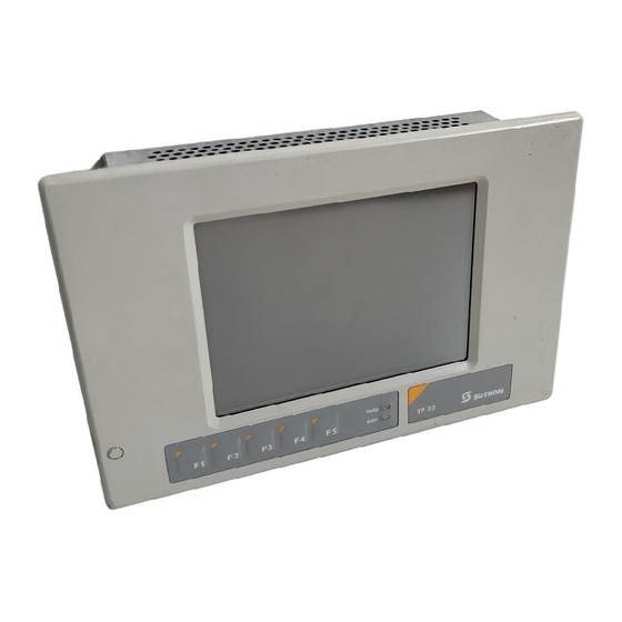
Control and Display Elements 3 Control and Display Elements Keyboard The keys are positioned under an environmental-proof polyester foil. You project the operating principle of the keys in the programming software. Figure 3-1 Front view Function Keys F1 to F5 Status LED Help Status LED Edit Display... -
Page 18: Status Leds
Control and Display Elements 3.1.2 Status LEDs The following status LEDs are at the operating device: Help Indicates an upcoming system message Edit Indicates the editing mode Touch Screen The device is equipped with a resistive 4 wire touch screen. You operate the device using this touch screen. -
Page 19: Key "Reset
Control and Display Elements Key "Reset" The reset key is located on the rear of the device. You can use this key to restart the device. Display Danger - Toxic! If the display is damaged, avoid touching, swallowing or breathing in the liquids or gases which may leak out! Danger - Corrosive! If the display is damaged, avoid touching, swallowing or breathing in the liquids or... -
Page 20: Default Contrast / Brightness Setting
Control and Display Elements If you did set up the system variable, you can set the contrast / brightness as follows. Enter the mask where you set up the system variable and: 1. Press the contrast / brightness button. 2. Enter a new value for the contrast / brightness. To do so, use the keyboard shown on the screen. -
Page 21: Interfaces Of The Device
Interfaces of the Device 4 Interfaces of the Device The device can either be supplied as a standard device or field bus device. The universal interface X3 combines several interface standards in one connector. The connector is divided into two channels. The communication channel (SER1) is operated separately from the channel for the upload/download/logging printer/scan- ner (SER2). -
Page 22: Standard Interfaces
Interfaces of the Device Standard Interfaces Figure 4-1 Rear view TTY / RS485 / RS232 1. Fastening Screw 2. Cable Fastener for Battery 3. Seal 4. Front Panel 5. Mounting Bolt 6. Nameplate 7. Threaded Bolt for Protective Grounding 8. Connector X1.A (Supply Voltage) 9. -
Page 23: Tty / 20 Ma Current Loop (X3-Ser1)
Interfaces of the Device 4.1.1 TTY / 20 mA Current Loop (X3-SER1) Depending on the wiring, it is possible to connect the interface either as an active or passive current loop. The transmit line and the receive line are each provided with a separate 20 mA power source. -
Page 24: Rs485 (X3-Ser1)
Interfaces of the Device 4.1.2 RS485 (X3-SER1) The interface is suitable for point-to-point and for multi-point connections. The wires belonging together are marked with „A“ and „B“. Some descriptions refer to the pins with „+“ and „-“ , where A = + and B = -. Signal Logic 1 <= -0.3 V i.e. - Page 25 Interfaces of the Device 4.1.2.2 Termination For point-to-point connections, always activate the termination. For multipoint con- nections, only activate the termination at the cable end. Figure 4-4 Block diagram termination RS422 / RS485 Table 4-5 Resistor values - termination RS422 / RS485 Designation Value R1, R3...
-
Page 26: Termination
Interfaces of the Device 4.1.3 RS232 (X3-SER1) The interface is suitable to establish a point-to-point connection. 4.1.3.1 Pin Assignment Figure 4-5 25 pin D-SUB female connector strip Connector in the terminal: 25 pin D-SUB female connector strip. Table 4-7 Pin assignment RS232 Designation Function Transmitted Data... -
Page 27: Rs232 (X3-Ser2)
Interfaces of the Device 4.1.4 RS232 (X3-SER2) The interface is only designed to be used for downloads, uploads, a scanner or a log- ging printer because the interface is not electrically isolated. 4.1.4.1 Pin Assignment Figure 4-6 25 pin D-SUB female connector strip Connector in the operating device: 25 pin D-SUB female connector strip. -
Page 28: Field Bus Interfaces
Interfaces of the Device Field Bus Interfaces 4.2.1 CAN (X2.1/X2.2) The opto decoupled interface for CAN bus connections is available to integrate the device into a CAN structure. The CAN bus is a high speed bus in accordance with ISO-DIS 11898. Figure 4-7 Rear view CAN... -
Page 29: Pin Assignment
Interfaces of the Device 1. Fastening Screw 2. Cable Fastener for Battery 3. Seal 4. Front Panel 5. Mounting Bolt 6. Nameplate 7. Threaded Bolt for Protective Grounding 8. Connector X1.A (Supply Voltage) 9. Reset Key 10. User Mode Switch 11. -
Page 30: Cable
Interfaces of the Device 4.2.1.2 Cable A shielded twisted-pair cable (cable type LiYCY-TP) complying with ISO 11898 must be used. The cable must have the following characteristics: Table 4-10 Cable characteristics CAN Parameters Value Impedance Min.: 108 Ohm Nom.: 120 Ohm Max.: 132 Ohm Specific Resistance 70 mOhm/m... -
Page 31: Devicenet (X2.1/X2.2)
Interfaces of the Device 4.2.2 DeviceNet (X2.1/X2.2) The opto-decoupled interfaces are available to integrate the device into a CAN struc- ture. The CAN bus is designed as a high speed bus in accordance with ISO-DIS 11898. Figure 4-10 Rear view DeviceNet 4-11... -
Page 32: Pin Assignment
Interfaces of the Device 1. Fastening Screw 2. Cable Fastener for Battery 3. Seal 4. Front Panel 5. Mounting Bolt 6. Nameplate 7. Threaded Bolt for Protective Grounding 8. Connector X1.A (Supply Voltage) 9. Reset Key 10. User Mode Switch 11. -
Page 33: Cable
Interfaces of the Device 4.2.2.2 Cable A DeviceNet-certified cable must be used. Table 4-14 Data line DeviceNet Cable Type Loop Resistance Surge Impedance Capacitance per Unit Length 2 x 1.1 mm < 22.6 Ohm/km 120 Ohm < 39.4 pf/m 2 x 0.6 mm <... -
Page 34: Interbus (X2.1/X2.2)
Interfaces of the Device 4.2.3 INTERBUS (X2.1/X2.2) The device can be integrated into the INTERBUS using the interfaces available for INTERBUS connections. Figure 4-13 Rear view INTERBUS 1. Fastening Screw 2. Cable Fastener for Battery 3. Seal 4. Front Panel 5. -
Page 35: Pin Assignment
Interfaces of the Device 4.2.3.1 Pin Assignment Figure 4-14 9 pin D-SUB male connector strip and female connector strip Connector in the terminal: 9 pin D-SUB male connector strip for remote bus in. Table 4-17 Pin assignment remote bus in (INTERBUS) Designation Function Data Input... -
Page 36: Diagnostic
Interfaces of the Device 4.2.3.3 Diagnostic The diagnostics LEDs are located at the rear of the operating device. The LEDs show the states of the bus system. Figure 4-15 Arrangement of the INTERBUS diagnostics LEDs The diagnostics LEDs at the operating device has the following functions: Table 4-19 Functions of the INTERBUS diagnostics LEDs Designation Color... -
Page 37: Interbus Opc Lwl (Do1/Di1/Do2/Di2)
Interfaces of the Device 4.2.4 INTERBUS OPC LWL (DO1/DI1/DO2/DI2) The device can be integrated into an INTERBUS device bus using the interfaces available for INTERBUS OPC LWL connection. Figure 4-16 Rear view INTERBUS OPC LWL 1. Fastening Screw 2. Cable Fastener for Battery 3. -
Page 38: Connector Pin Assignment
Interfaces of the Device Never look directly into the open end of an optical fiber cable. Infrared light can cause damage to the retina of the eye. Fit the open ends of an optical fiber cable and the connections with protective caps. Wear protective goggles. The sending and receiving units can be rendered unusable by dirt accumulation. - Page 39 Interfaces of the Device Table 4-21 Functions of the INTERBUS OPC LWL diagnostics LEDs Designation Color State Function Yel- Remote Bus Inactive Green PCP Active PCP Not Active Yel- Incoming Optical Fiber Path Not OK Incoming Optical Fiber Path OK Yel- Outgoing Optical Fiber Path Not OK Outgoing Optical Fiber Path OK...
-
Page 40: Mpi (X2)
Interfaces of the Device 4.2.5 MPI (X2) The device can be integrated into a Siemens MPI bus structure using the interface available for Siemens MPI connections. Figure 4-18 Rear View MPI 1. Fastening Screw 2. Cable Fastener for Battery 3. Seal 4. -
Page 41: Pin Assignment
Interfaces of the Device 4.2.5.1 Pin Assignment Figure 4-19 9 pin D-SUB female connector strip Connector in the terminal: 9 pin D-SUB female connector Table 4-22 Pin assignment MPI Designation Function Not Connected Not Connected RxD/TxD-P Received Data / Transmitted Data Plus CNTR-P Repeater Control Signal Plus DGND... -
Page 42: Diagnostic
Interfaces of the Device 4.2.5.4 Diagnostic A diagnostics LED is located at the rear of the operating device. The LED shows a state of the bus system. Figure 4-20 Arrangement of the MPI diagnostics LED The diagnostics LED at the operating device has the following function: Table 4-24 Function of the MPI diagnostics LED Color State... -
Page 43: Profibus-Dp (X2)
Interfaces of the Device 4.2.6 PROFIBUS-DP (X2) The interface for PROFIBUS-DP connections is available to integrate the device into a PROFIBUS-DP structure. Figure 4-21 Rear view PROFIBUS-DP 1. Fastening Screws 2. Cable Fastener for Battery 3. Seal 4. Front Panel 5. -
Page 44: Pin Assignment
Interfaces of the Device 4.2.6.1 Pin Assignment Figure 4-22 9 pin D-SUB female connector strip Connector in the operating device: 9 pin D-SUB female connector. Table 4-25 Pin assignment PROFIBUS-DP Designation Function Not Connected Not Connected RxD/TxD-P Received Data / Transmitted Data Plus CNTR-P Repeater Control Signal Plus DGND... -
Page 45: Diagnostics
Interfaces of the Device 4.2.6.3 Diagnostics A diagnostics LED is located on the rear of the operating device. The LED shows the states of the bus system. The diagnostics LED on the operating device has the following functions: Table 4-28 Function of the PROFIBUS-DP diagnostics LED Color State Function... -
Page 46: Memory Card (Option)
Interfaces of the Device Memory Card (Option) You can insert a CompactFlash card on the side of your operating device. The Com- pactFlash card allows you to exchange projects between the PC and the operating device. You can recognize the rear side of a CompactFlash card by the notches on each side of the card. -
Page 47: Shielding D-Sub Connectors
Interfaces of the Device Shielding D-SUB Connectors You must shield D-SUB connectors as follows: Figure 4-26 Shielding D-SUB connectors D-SUB connector Shield Cable clip Cable The shield must be folded back into a flat position over the cable sheath. When fastening the cable with the cable clip, as much of the shielding as possible must be in contact with the housing and sufficient strain relieve must be ensured. - Page 48 Interfaces of the Device 4-28...
-
Page 49: Maintenance And Servicing
Maintenance and Servicing 5 Maintenance and Servicing Front Panel Only use a damp cloth to remove any dirt from the front panel. Fuse The semiconductor fuse cannot be replaced! A semiconductor fuse is used to protect the device. Once the fuse has been tripped, the device must be disconnected from the supply voltage to allow the semiconductor fuse to regenerate. -
Page 50: Changing The Battery
Maintenance and Servicing 5.3.1 Changing the Battery Batteries must only be changed by authorized and trained experts! For changing the battery you may only use replacement batteries of Sütron electronic. Electrostatic discharge can damage electronic components. Observe the ESD pro- tective measures! Do not throw lithium batteries into fire, heat to 100 °C (212 °F) or higher and do not recharge. -
Page 51: Battery Disposal
Maintenance and Servicing 5.3.2 Battery Disposal To prevent short circuitry in the collection boxes, insulate the poles of each battery with insulation tape or put each single battery into a plastic bag. You must always return old batteries to a dealer or to a returns depot set up for this purpose by the public waste disposal body or a licensed battery dealer for recycling. - Page 52 Maintenance and Servicing...
-
Page 53: Technical Data
Technical Data 6 Technical Data Keyboard Type Membrane Keyboard Number of Keys 5 Function Keys Key Area (Embossment) 12 mm x 12 mm (0.473" x 0.473") Actuator Travel 0.6 mm (0.024") Activation Power Switching Cycles Approx. 3 Million under the following conditions: Keystroke Element: Testing Ram (DIN 42115) Keystroke Load: 10 N Keystroke Frequency: 1 Hz... - Page 54 Technical Data Display TP22EM TP22ES TP22ET Lines Characters/Line Display Area (H x W) 90 mm x 120 mm 90 mm x 120 mm 90 mm x 120 mm (3.543" x 4.724") (3.543" x 4.724") (3.543" x 4.724") Electrical Data Supply Voltage 24 V DC (SELV in Accordance with DIN EN 61131) Residual Ripple 10% Maximum...
- Page 55 Technical Data Field Bus Interfaces X2.1 / X2.2 INTERBUS Electrically Isolated DO1 / DI1 / DO2 / DI2 INTERBUS OPC Electrically Isolated Optical Fiber X2 MPI Electrically Isolated X2 PROFIBUS-DP Electrically Isolated Central Unit Central Unit 32-bit RISC CPU Clock Frequency 74 MHz Other Characteristics Watchdog Timer, Real-Time Clock, Temperature Compensa-...
- Page 56 Technical Data Standards and Guidelines Interference Immunity EN 61000-4-2 EN 61000-4-3 EN 61000-4-4 EN 61000-4-5 EN 61000-4-6 EN 61000-6-2 Emitted Interference EN 50081-1 EN 55022 Equipment Requirements EN 61131 Storage and Transportation EN 61131 Part 2 Power Supply EN 61131 Part 2 Electromagnetic Compatibility 89/336/EEC (Including all Applicable Amendments) Degree of Protection...
- Page 57 Ordering Data 7 Ordering Data Table 7-1 Accessories Description Article No. CompactFlash Card 16 MB 81152.000 CompactFlash Card 32 MB 81152.032 CompactFlash Adapter for Laptop 81166.000 CompactFlash Adapter for PC 81167.000 25 Pin Download Cable 88175.030 USB-RS232 Converter for Download (Only in Combination with 88175.030) 81215.000 Protection Foil for Touch Screen 5,7’’...
- Page 58 Ordering Data...
- Page 59 A Index DeviceNet (X2.1/X2.2) ......4-11 INTERBUS (X2.1/X2.2)......4-14 Accessories............7-1 INTERBUS OPC LWL......4-17 MPI (X2)..........4-20 PROFIBUS-DP (X2)........ 4-23 Battery............... 5-1 RS232 (X3-SER1)........4-6 Battery disposal ..........5-3 RS232 (X3-SER2)........4-7 Brightness setting ..........3-3 RS485 (X3-SER1)........4-4 TTY / 20 mA (X3-SER1) ......
- Page 60 Target group............1-2 Technical data........... 6-1 Termination CAN ............4-10 DeviceNet ..........4-13 MPI............4-21 RS232 ............4-6 RS485 ............4-5 TTY / 20 mA..........4-3 Touch screen ............ 3-2 Unpacking ............2-1 User mode switch..........3-2...
- Page 62 Sütron electronic GmbH Kurze Straße 29 D-70794 Filderstadt Phone: 0049 711 / 77098-0 Fax: 0049 711 / 77098-60 E-mail: doku@suetron.de Internet: www.suetron.com...
Need help?
Do you have a question about the TesiMod TP22 and is the answer not in the manual?
Questions and answers