Table of Contents
Advertisement
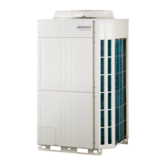
VRF SYSTEM
OUTDOOR UNIT
□
AJ
A72LALH
□
AJ
A90LALH
□
AJ
108LALH
INSTALLATION MANUAL
For authorized service personnel only.
Contents
1. SAFETY PRECAUTIONS ................................. 2
2. ABOUT THE PRODUCT .................................... 4
2. 1. Caution when using R410A refrigerant............ 4
2. 2. Special tools for R410A .............................. 4
2. 3. Accessories ............................................. 4
2. 4. Combinations .......................................... 4
2. 5. Option parts ............................................. 5
2. 6. Header ................................................... 5
3. INSTALLATION WORK .................................... 6
3. 1. Selecting an installation location .................. 6
3. 2. Drain processing ....................................... 6
3. 3. Installation dimensions .............................. 7
3. 4. Transportation the outdoor unit ..................... 9
3. 5. Installation the unit ................................. 10
4. SYSTEM CONFIGURATION ........................... 11
4. 1. System confi guration .............................. 11
4. 2. Pipe selection ....................................... 12
4. 3. Protection of pipes ................................. 13
5. PIPE INSTALLATION .................................... 13
5. 1. Brazing ................................................ 13
5. 2. Indoor unit pipe connections ..................... 13
5. 3. Piping method ....................................... 14
5. 4. Multiple connections .............................. 16
6. ELECTRICAL WIRING .................................... 18
6. 1. The precautions of electrical wiring ............ 18
6. 2. Knockout hole ....................................... 19
6. 4. Transmission line .................................... 21
6. 5. Wiring method ....................................... 22
□
AJ
126LALH
□
AJ
144LALH
6. 6. External input and external output ............ 24
7. FIELD SETTING .......................................... 27
7. 1. Field setting switches .............................. 27
7. 2. DIP switch setting ................................. 27
7. 3. Rotary switch setting .............................. 29
7. 4. Push button setting ................................. 29
7. 5. Address setting for signal amplifi ers ............ 33
7. 6. Indoor unit address setting ........................ 33
(Measure with breaker OFF) ..................... 35
8. PIPE INSTALLATION II ................................. 36
8. 1. Sealing test .......................................... 36
8. 2. Vacuum process .................................... 37
8. 3. Additional charging ................................. 37
8. 4. Installing insulation ................................. 39
9. TEST RUN ................................................... 40
9. 1. Pre-test run check items ........................... 40
9. 2. Test operation method ........................... 40
9. 3. Checklist ............................................. 42
10. LED Display ................................................ 42
10. 1. Normal operation mode ........................... 42
10. 2. Error display mode ................................. 43
11. INFORMATION ............................................. 44
PART NO. 9378945029-03
Advertisement
Table of Contents

Related Manuals for Fujitsu AJ*A72LALH Series


Summary of Contents for Fujitsu AJ*A72LALH Series
-
Page 1: Table Of Contents
VRF SYSTEM OUTDOOR UNIT □ □ A72LALH 126LALH □ □ A90LALH 144LALH □ 108LALH INSTALLATION MANUAL For authorized service personnel only. Contents 1. SAFETY PRECAUTIONS …………………………… 2 6. 6. External input and external output ………… 24 7. FIELD SETTING …………………………………… 27 2. -
Page 2: Safety Precautions
SAFETY PRECAUTIONS • Be sure to read this Installation manual thoroughly before installation. • The warnings and precautions indicated in this Installation manual contain important information pertaining to your safety. Be sure to observe them. • After installing the unit, perform a test run to make sure the unit operates normally. Then, explain to the customer how to operate and maintain the unit. - Page 3 • Do not place the outdoor unit near the handrail of the balcony. Children may climb onto the outdoor unit, lean over the handrail and fall over. • Use only a specifi ed power cable. Poor connection, poor insulation, and exceeding the allowable current will lead to electric shock and fi...
-
Page 4: About The Product
ABOUT THE PRODUCT 2. 1. Caution when using R410A refrigerant Pay careful attention to the following points : • Since the working pressure is 1.6 times higher than that of R22 models, some of the piping and installation and service tools are special. (See the table in the SPECIAL TOOLS FOR R410A section.) Especially, when replacing a conventional refrigerant (other than R410A) model with a new refrigerant R410A model, always replace the conventional piping and fl... -
Page 5: Option Parts
Outdoor Unit Model Name Nominal System Capacity (HP) AJ A72LALH AJ A90LALH AJ 108LALH AJ 126LALH AJ 144LALH Installation space combination Combination (HP) Outdoor Unit 1 (HP) Outdoor Unit 2 (HP) Outdoor Unit 3 (HP) Maximum Connectable Indoor Unit When connecting outdoor units, install the outdoor unit with the largest nominal system capacity nearest to the refrigerant pipe and indoor unit, followed by those with lesser nominal system capacities. -
Page 6: Installation Work
INSTALLATION WORK Please obtain the approval of the customer when selecting the location of installation and installing the main unit. 3. 1. Selecting an installation location WARNING • Install the unit in a location that can withstand its weight, and where it will not topple or fall. •... -
Page 7: Installation Dimensions
3. 3. Installation dimensions CAUTION When installing the outdoor unit, pay attention to the following items. • Provide suffi cient installation space, such as transportation route, maintenance space, ventilation space, refriger- ant piping space, and passageways. • Pay attention to the specifi cations of the installation space as shown in the fi gure. If the unit is not installed ac- cording to specifi... - Page 8 Fig. Fig. <Front view> <Side view> <Front> <Rear> Wall Wall Wall Wall Fig. Fig. <Top view> <Top view> 500mm 800mm or more or more 800mm 1000mm or more or more 20mm or 20mm or 20mm or 20mm or more more more more 3.
-
Page 9: Transportation The Outdoor Unit
Concentrated Installation • The wall (without height restrictions) must not exist on the both sides (left / right) of outdoor unit. Also, must not ex- ist on the both sides (front / rear) of outdoor unit. • Ventilation resistance can be ignorable when the distance from a wall or product, etc. is larger than 2m. Fig. -
Page 10: Installation The Unit
Conveying by forklift (Fig.B) • When using the forklift to convey the unit, pass the forklift arms through the opening space as shown in below. Front : Bottom of the wooden delivery pallet. Side : Space between pallet and cabinet. •... -
Page 11: System Configuration
SYSTEM CONFIGURATION 4. 1. System confi guration CAUTION • When connecting multiple outdoor units, set the nearest outdoor unit to the indoor unit on the refrigerant pipe as the master unit. • When connecting multiple outdoor units, install the outdoor unit with the largest nominal system capacity nearest to the indoor unit and on the refrigerant pipe, followed by those with less nominal system capacities. -
Page 12: Pipe Selection
4. 2. Pipe selection Master Slave Slave unit unit1 unit2 CAUTION • This unit is designed specifi cally for use with the Pipe size R410A refrigerant. (table B) • Pipes for R407C or R22 may not be used with this Pipe size Outdoor unit First separation... -
Page 13: Protection Of Pipes
4. 3. Protection of pipes • Protect the pipes to prevent the entry of mois- Location Working period Protection method ture and dust. 1 month or more Pinch pipes • Especially pay attention when passing the pipes Outdoor Less than 1 month Pinch or tape pipes through a hole or connecting the end of a pipe Indoor... -
Page 14: Piping Method
CAUTION 0.5m or more Separation tube Separation tube 0.5m or more Main pipe To indoor To indoor unit unit To indoor unit Header Header 0.5m or more 0.5m or more Main pipe To indoor unit To indoor unit To indoor unit •... - Page 15 5. 3. 2. Removing the pinch pipe WARNING Remove the pinch pipe only when the internal gas is completely drained. If gas still remains inside, the piping may crack if you melt the brazing fi ller metal of the junction area with a burner. Before connecting the piping, remove the pinch pipe in accordance with the following instructions: Verify that the liquid side and gas side 3-way valves are closed.
-
Page 16: Multiple Connections
5. 4. Multiple connections CAUTION • When connecting multiple (maximum 3) units, be sure to install the unit with the largest capacity nearest to the indoor unit. For example) AJ 126LALH (Outdoor Unit1) + AJ 126LALH (Outdoor Unit2) + AJ A90LALH (Outdoor Unit3) •... - Page 17 Fig. Examples of multiple unit installation (Example 1) (Example 3) Master unit Slave unit1 Slave unit2 Master unit (Example 2) Slave Master unit Slave unit1 Slave unit2 unit1 Slave unit2 CAUTION To prevent the oil from settling in the stopped unit, install the pipes between the outdoor units so that they are level or are tilted upward to the outdoor units.
-
Page 18: Electrical Wiring
ELECTRICAL WIRING 6. 1. The precautions of electrical wiring WARNING • Wiring connections must be performed by a qualifi ed person in accordance with specifi cations. The rated supply of this product is 50Hz, 400V of 3-phase, 4-wire. Use a voltage within the range of 342-456V. •... -
Page 19: Knockout Hole
6. 2. Knockout hole CAUTION • Be careful not to deform or scratch the panel while opening the knockout holes. • After opening the knockout hole, remove the burr on the edges to prevent snapping of wires. It is recommended to apply rust proof paint on the edges to prevent rust. Electric wires can be connected from the front or from the left. -
Page 20: Selecting Power Supply Cable And Breaker
6. 3. Selecting power supply cable and breaker CAUTION • Obtain the distribution network operator's agreement about the power capacity of the power supply system, specifi cation of the cable and the harmonic current, and etc. when you connect the outdoor unit with the power supply. -
Page 21: Transmission Line
6. 4. Transmission line CAUTION • Caution when wiring cable When stripping off the coating of lead wire, always use the exclusive tool such as a wire stripper. If there is no 2pcs at one side Wires twisted 1 wire exclusive tool available necessarily, carefully strip the coating by a cutter etc. -
Page 22: Wiring Method
6. 4. 3. Enabling/Disabling automatic address setting You can enable/disable automatic address setting for the indoor unit and the signal amplifi er. To enable automatic address setting for the indoor unit, connect the indoor unit to outdoor units under the same refrig- erant system.(Fig.4) Example : Disable Automatic Address setting Example : Enable Automatic Address setting... - Page 23 Secure with a cable clamp as shown in the fi gure below. Power terminal board Binder Cable clip Ring terminal: M8 Cable clip Binder Transmission cable Power supply cord Tightening torque M3 screw 0.5 to 0.6 N·m (5 to 6 kgf·cm) M8 screw 5.0 to 7.0 N·m (50 to 70 kgf·cm) Use a ring terminal to connect the electric wires to the power supply terminal board.
-
Page 24: External Input And External Output
6. 6. External input and external output 6. 6. 1. Terminal position Base heater Output 1 Output 2 Terminal(CN115) Terminal(CN136) Terminal(CN137) Input 4 BASE HEATER EXT. OUT. 1 EXT. OUT. 2 Terminal(CN134) EXT. OUT. 1 EXT. OUT. 2 CN136 CN137 (BLUE) BASE HEATER (BLACK) CN115... - Page 25 6. 6. 2. External input terminal Service parts : EXTERNAL INPUT WIRE A (9368777005) • Setting to low noise mode, cooling priority/heating priority selection, outdoor unit operation peak control setting, emergency/batch stop and electricity meter pulse are possible from the outside. •...
- Page 26 6. 6. 3. External output terminal Service parts : EXTERNAL INPUT WIRE A (9368777005) • You can detect the operation condition of outdoor unit and the abnormal situation of both indoor and outdoor unit. • The external output terminal is only valid for Master Unit. Wiring method and specifi...
-
Page 27: Field Setting
FIELD SETTING CAUTION Discharge the static electricity from your body before setting up the DIP switches. Never touch the terminals or the patterns on the parts that are mounted on the board. 7. 1. Field setting switches Remove the front panel of the outdoor unit and the cover of the electrical component box to access the print circuit board of the outdoor unit. - Page 28 Number o f outdoor units installed The number of outdoor units installed in 1 refrigerant system must be set. Set for all outdoor units. SET5 Number of out- Remarks door units (Factory setting) Forbidden 7. 2. 3. Terminating resistor setting Caution Be sure to set the terminal resistor according to specifi...
-
Page 29: Rotary Switch Setting
7. 3. Rotary switch setting The rotary switch (REF AD) sets the refrigerant circuit address of the outdoor unit. Confi gure the settings only on the master unit of a refrigerant system. If multiple refrigerant systems are connected, set the rotary switch (REF AD) as shown in the table below. Rotary Setting Switch Setting... - Page 30 First press priority This item allows you to set the priority item in the cooling cycle operation mode. • First press priority: The operation mode that is confi gured fi rst will be given priority. Outdoor unit external input • Outdoor unit external input priority: The operation mode that is confi gured priority Priority mode through the external input terminal "CN132"...
- Page 31 Electricity meter Set the digit positions for the hundreds and thousands of the pulse settings of the electricity meter connected to CN135. pulse setting 2 (Setting disabled) (Factory default) Turn on the power of the outdoor unit and enter standby mode. •...
- Page 32 Setting method Use the MODE/EXIT, SELECT, and ENTER buttons 1: FUNCTION Setting to confi gure settings according to the procedures 7 segment LED display below. First 2 digits Last 2 digits (LED105, LED104) [1: FUNCTION Setting] → [2: Setting the fi rst (the display when the main power is turned on) 2 digits] →...
-
Page 33: Address Setting For Signal Amplifi Ers
7. 5. Address setting for signal amplifi ers 7. 5. 1. Address setting for signal amplifi ers When using signal amplifi ers, the address for signal amplifi ers must be set. The address for signal amplifi ers can be set automatically from 1 outdoor unit (master unit) on the network. Refer to the next section “Fig. - Page 34 Fig. Wiring example for automatic address setting (1) Signal amplifi er wiring example (2)(3)(4) Indoor unit wiring example (Connect the indoor and outdoor units of the same refrigerant system as shown below.) Refrigerant system1 Signal amplifi er (2) Master unit Refrigerant system2 Master unit Signal amplifi...
-
Page 35: Resistance Measurement Of Transmission Cable (Measure With Breaker Off)
7. 7. Resistance measurement of transmission cable (Measure with breaker OFF) CAUTION Do not turn on the power if the resistance between the terminals of the transmission cable is abnormal. Otherwise, the circuit board may be damaged. Measure the resistance between 2 terminals of a Distance from termination resistor (m) transmission cable. -
Page 36: Pipe Installation Ii
PIPE INSTALLATION II Fig. A Connection system In case of connected 1 outdoor unit In case of connected many outdoor units Pressure regulating valve Outdoor unit Outdoor unit Outdoor unit Pressure regulating Pressure gauge valve Pressure gauge Nitrogen Nitrogen Indoor Indoor Vacuum unit... -
Page 37: Vacuum Process
8. 2. Vacuum process CAUTION • Do not turn on the power unless all operations are complete. • If the system is not evacuated suffi ciently, its performance will drop. • If moisture might enter the piping, follow below. (i.e., if doing work during the rainy season, if the actual work takes long enough that condensation may form on the inside of the pipes, if rain might enter the pipes during work, etc.) •... - Page 38 8. 3. 2. Checking total amount of refrigerant and calculating the amount of refrigerant charge to be added • The amount of refrigerant charge to be added is the total value of the basic refrigerant charge amount and the value calculated from the length of the liquid pipe. •...
-
Page 39: Installing Insulation
<Calculation> 144LALH , AJ 126LALH, AJ 108LALH) connected to 1 system • When there are 3 outdoor units (AJ Calculation of additional amount for outdoor unit A=3.30(kg)+3.30(kg)+1.20(kg)=7.80(kg) Calculation of additional amount for pipe length If liquid pipe piping length is the following ф19.05 : 50m, ф15.88 : 25m, ф12.70 : 0m, ф9.53 : 20m, ф6.53 : 15m Additional charge volume B=50(m)×0.268(kg/m)+25(m)×0.178(kg/m)+0(m)×0.114(kg/m) +20(m)×0.058(kg/m)+15(m)×0.021(kg/m) -
Page 40: Test Run
TEST RUN 9. 1. Pre-test run check items Before the test operation, check the following items. Is there a gas leakage? (At pipe connections {fl ange connections and brazed areas}) Is the system charged with the specifi ed volume of refrigerant? Is the refrigerant circuit address correct? Is a breaker installed at the power supply cable of every outdoor unit? Are the wires connected to the terminals without looseness, and in accordance with the specifi... - Page 41 1: FUNCTION Setting First 2 digits Last 2 digits (the display when the main power is turned on) Press the MODE/EXIT button. (Blinking) Press the SELECT button. (Blinking) Press the SELECT button. (When [F4] to [F9] are displayed, continue to press the SELECT button until [F3] is displayed.) Press the ENTER button.
-
Page 42: Checklist
9. 3. Checklist Check description Check method Criteria Cooling: low pressure approx. 0.8 MPa High and low pressure values are normal. Check it with a pressure gauge. Heating: high pressure approx. 3.0 MPa Drain water is discharged smoothly through Check it by pouring water. ―... -
Page 43: Error Display Mode
10. 2. Error display mode Mode Code Description Mode Code Description E 1 3. 1 Communication error between Outdoor unit E 9 2. 1 Compressor 2 error Communication E 1 4. 1 Outdoor unit network communication 1 error E 9 2. 2 Compressor 2 overcurrent error error E 1 4. -
Page 44: Information
Dry-bulb temperature and wet-bulb temperature under standard cooling/heating condition Condition of max. cooling Dry-bulb temperature and wet-bulb temperature at maximum electric current and input Manufacture year Manufacture year Origin Origin country Manufacturer Manufacturer FUJITSU GENERAL LIMITED Address : 1116, Suenaga, Takatsu-ku, Kawasaki 213-8502, Japan Label En-44...