Table of Contents
Advertisement
Advertisement
Table of Contents

Related Manuals for Leica MX420

Summary of Contents for Leica MX420
- Page 1 MX420 Navigation System Operator’s Manual...
-
Page 2: Product Information
MX420/MKD MX420/AIS DGPS IMPORTANT NOTICE!! THE MX420 IS AN AID TO NAVIGATION ONLY. UNDER NO CIRCUM- STANCES SHOULD IT BE USED IN LIEU OF AUTHORIZED GOVERN- MENT CHARTS. ITS ACCURACY CAN BE AFFECTED BY MANY FAC- TORS SUCH AS EQUIPMENT DEFECTS, ENVIRONMENTAL CONDI- TIONS, OR IMPROPER OPERATION. - Page 3 Symbols Used In This Manual Danger Indicates an imminently hazardous situation which, if not avoided, will result in death or serious injury. Warning Indicates a potentially hazardous situation which, if not avoided, could result in death or serious injury. Caution Indicates a potentially hazardous situation which, if not avoided, may result in minor or moderate injury and/or appreciable material, finan- cial and environmental damage.
- Page 4 This manual is organized by describing first the various MX420 mod- els covered in this book. Then the special front panel features includ- ing the traffic light indicator. The sections that follow detail each pri- mary function as it is presented on the front panel (i.e.
- Page 5 How To Contact Us? Contact your local MX Marine dealer for: • Installation, Service, & Technical Support • Sales of Accessories • Hardware and Software Upgrades Unlike many other consumer electronics industries which only sell consumer electronic devices, your marine dealer is often your best advisor for installation and service of your new GPS receiver.
-
Page 6: Table Of Contents
MX420/2 DGPS ............... 3 MX420/8 GPS ................3 MX420/8 DGPS ............... 3 MX420/BR ................4 MX420/BRIM (Dual Control Integrity Monitor) ......4 MX420/AIS Basic (Automatic Identification System-Basic) ..5 MX420/AIS (AIS & Navigation System) ........5 DGPS Beacon System ................6 Keypad &... - Page 7 Operator Manual Table of Contents Mark Position .............. 11 GOTO ................12 LIGHT ................12 POWER ON/OFF ............12 MAN OVER BOARD (MOB) ......... 13 E (EDIT) ..............14 C (CLEAR) ..............14 CURSOR ..............14 FUNCTION ..............14 N AV Automatic Identification System (AIS) ......
- Page 8 Table of Contents Operator’s Manual Maneuvering Within the Route ..........38 Scrolling ................38 Skipping and Unpassing Waypoints ........ 38 Inserting Waypoints or Routes into an Existing Route ..39 Reversing the Active Route ..........41 ETA Setup ................43 SOG Based on Arrival Date &...
- Page 9 Operator Manual Table of Contents PLOT 2 - Relative to Marker ............77 PLOT3 ..................77 Plot Screen Use Examples ............78 Station Keeping ..............78 Grid Search ................79 Man Over Board ................80 Remote MOB ................81 Tide ......................82 TIDE1 - Current Tide Display ............
- Page 10 Table of Contents Operator’s Manual Configuration ..................... 99 AIS Config ................99 AIS Static ..................99 AIS Voyage .................. 99 Alarms ..................99 Anchor - Anchor Watch Alarm ............ 100 COG SOG - Course & Speed Filter Settings & Setup ....100 Compass - External Compass Input &...
- Page 11 Operator Manual Table of Contents Time - Mode and Format Control ..........129 Wind ..................130 Wpt & Rte Input - Uploading Waypoints into the Receiver ..131 Appendix A - Automatic Identification System (AIS) ........ 133 Introduction ................133 AIS System Setup ..............
-
Page 12: About Gps Navigation
About GPS Navigation Operator’s Manual About GPS Navigation This GPS receiver is a precision navigation instrument utilizing the latest technology available today to provide optimum performance from the GPS satellite and Beacon land signals received. As with all other forms of radio signals, the ultimate navigation result is depen- dent upon the quality of these signals. -
Page 13: Special Notes
Operator’s Manual About GPS Navigation Special Notes Never rely solely on any single navigational aid. Always use whatever information is available, and cross-check information when possible. GPS expected position accuracy is better than 30 meters (95% of the time) but may be up to 100 meters occasionally. The derived speed and course readings may be hampered accordingly. -
Page 14: Functional Description
MX420 configurations and their differences. MX420/2 GPS This is a basic MX420 Control and Display Unit (CDU) model with two (2) bidirectional user NMEA ports. This model is supplied with a MX421- 10 GPS only smart antenna. The smart antenna can achieve autono- mous GPS accuracy better than 3 meters. -
Page 15: Mx420/Br
Operator’s Manual Functional Description MX420/BR This is a dual-head CDU system where a MX420/8 (operating as a master) and a MX420/2 (operating as a slave) are supplied. A smart DGPS antenna (MX421B-10) is supplied as a standard equipment. The antenna unit is connected only to the MX420/8 master unit. -
Page 16: Mx420/Ais Basic (Automatic Identification System-Basic)
An entry level MX420/AIS CDU model supplied with an IMO-compli- ant AIS transponder unit. All the AIS transponder setups and controls are done through the MX420. It also gathers the ship’s sensor data and organizes the information for transmission via AIS. High-speed serial data ports are provided for output to the ECDIS chartplotter, ARPA radar and other shipboard systems. - Page 17 Operator’s Manual Keypad & Display Description 2) Three smart GPS/DGPS antenna models are compatible with the MX420 CDU. They are the MX421-10 (GPS or DGPS), MX525 (DGPS only) and MX521(GPS or DGPS ). Version 2.0...
-
Page 18: Dgps Beacon System
Keypad & Display Description Operator’s Manual DGPS Beacon System As Maritime Safety Administrations, Navy, and Coast Guard Organi- zations realize the limitations of standard GPS positioning, many have begun installing DGPS Beacon Stations. While an understanding of this system is not necessary for operating receivers with internal bea- con receivers, you may want to read on to have a better understanding of how your receiver is capable of achieving the high levels of accu- racy made possible by this network of transmitters. -
Page 19: Keypad & Display Description
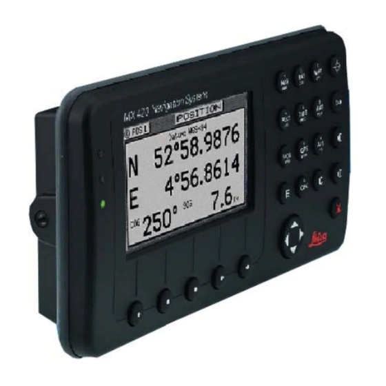
Operator’s Manual Keypad & Display Description Keypad & Display Description Traffic Display Function Keys Lights R T E N A V W P T P L O T A U X T I D E P O S G P S A I S C F G 6289-01A.400... -
Page 20: Differential Gps Traffic Light Operation
Keypad & Display Description Operator’s Manual Differential GPS Traffic Light Operation: Red Flashing Not tracking satellites (no position update). This is normal for the first 2 minutes or so when turning the unit on. The very first time you turn the unit on, or if the memory is reset or lost, this condition is also normal. -
Page 21: Yellow Solid
Operator’s Manual Keypad & Display Description Yellow Solid DGPS position update with poor HDOP value. You may see this from time to time during normal operation. It usually occurs when you are tracking 3, 4, or 5 satellites, and the satellites have poor geometry relative to your position. -
Page 22: Yellow Solid
Keypad & Display Description Operator’s Manual minutes after changing to Red Solid to collect an almanac from the satellites, regardless of whether a position update has been calculated or not. This is also a normal indication if the HDOP is greater than 10. The HDOP value can be read in the GPS function screens. -
Page 23: The Softkeys
Operator’s Manual Keypad & Display Description With the exception of a portion of the PLOT and MOB screens which use two softkeys to change the view scale, all of the screens require that you press the E (Edit Mode) function key before you are allowed to change data on the screen. -
Page 24: Goto
Keypad & Display Description Operator’s Manual capable of performing this function from a remote contact closure in- put via Cable B (MOB/Event) wire. Refer to the Installation & Service Manual for interface instructions. GOTO This function key allows you to quickly create a route from your present position to one other waypoint. -
Page 25: Man Over Board (Mob)
To cancel a MOB condition, make sure you are in the MOB Plot screen. Press the E function key, then select the Cancel MOB softkey. This MX420 receiver is also capable of performing the MOB function from a remote contact closure. If the contact closure is made for less... -
Page 26: E (Edit)
Navigate Operator’s Manual than 2 seconds, the input is registered as a Mark Position. If the con- tact closure is made for more than 2 seconds, the input is registered as a MOB Position. Refer to the Installation & Service Manual for inter- face instructions. - Page 27 Operator’s Manual Navigate when you are in the edit mode. You will find that they are most often used in the RTE, WPT, and CFG screens, but they are used in other screens as well. If you are trying to enter text, simply locate the desired letter and press the appropriate key repeatedly until the appropriate letter or number appears.
-
Page 28: Ais
Note: The AIS display key is not functional in the MX420/2 and MX420/8 mod- els. This is a special key that is active only in the MX420/AIS or MKD models. Non-AIS models will show the message “AIS Not Available on this Version”... -
Page 29: Navigate
Operator’s Manual Navigate Navigate There are four basic NAV screens. NAV4 only provides data if appro- priate sensors (e.g. wind speed/direction logs, NMEA compass, etc.) are interfaced and activated on the CDU. The NAV functions are highly interactive with the RTE1 screen, and a number of CFG menu selec- tions. -
Page 30: Dead Reckoning
CDU to do exactly what you want it to. Dead Reckoning The MX420 CDU is capable of Dead Reckoning (DR) calculation when appropriate compass/heading and speed log sensors are connected and activated. Refer to the NAV4 and CFG sections of this document. - Page 31 Operator’s Manual Navigate The somewhat triangular shape at the bottom center of the screen represents the bow of the boat. Icons on the screen are always related to this object. The two dash lines extending from the bottom of the screen towards the center of the screen represent your cross-track error limits.
- Page 32 Navigate Operator’s Manual If you press the E key, the Panorama Display Option screen will allow you to customize the information presented. View - allows you to adjust the display for a Close (zoomed-in) or a Far (zoomed-out) representation of your route. Show Waypoints - allows you to turn waypoints which are not part of the active route on and off.
-
Page 33: Nav2 - Basic Steering Information
Operator’s Manual Navigate NAV2 - Basic Steering Information Navigate screen 2 provides the bearing (BRG) and range (RNG) to the waypoint you are approaching in large easily viewed characters. Be- low these, you will see your actual Course Over Ground (COG) and Speed Over Ground (SOG). -
Page 34: Nav 3 - Expanded Navigation Information
Navigate Operator’s Manual From time to time, you might drift off course and decide not to return to your original course line. If you drift outside of your cross-track error limit, you can reset your course line from your present position to the waypoint by pressing the E key and selecting Reset XTE from the display. -
Page 35: Nav4 - Sensor Input Navigation
Operator’s Manual Navigate You will find the right hand window to be a helpful tool. In addition to identifying the waypoint you are currently approaching, it identifies the waypoint at the end of the next leg. The really unique feature of this screen is the graphical representation of your actual course line approach angle relative to the next leg of your course. - Page 36 Navigate Operator’s Manual records may contain depth information. This provides you the ca- pability of knowing the depth source exactly. Log - Sets the input port number, sensor type (pulse or NMEA 0183), sensor offset, alarms, and a correction factor (if needed). Set &...
- Page 37 Operator’s Manual Navigate The window below the wind data provides information relating to your course and speed. You will find the Course Over Ground (COG calcu- lated by the MX421 smart GPS antenna), Heading (HDG, your NMEA 0183 compass input), and Heading To Steer (HTS) data on the left side of the window.
- Page 38 Below the depth data you will find the next route leg vector, the Range to the waypoint and Time To Go data, explained in the NAV3 section. Note: The NAV function is not active in the MX420/AIS Basic model without the MX421 antenna.
-
Page 39: Route
Operator’s Manual Route Route There are two RTE screens. The NAV functions are highly interactive with the RTE1 screen. The RTE2 screen allows you to create a pool of predetermined routes that you might use often, so you need only create the route one time. -
Page 40: Rte1 - The Active Route
GOTO Operator’s Manual main intact in the RTE2 screen. The following CFG1 menus directly impact the RTE functions: Navigation - sets a variety of important functions and alarms. Rhumb line or Great Circle navigation Range units: nautical miles, nautical miles and meters (when under 1,000 meters), nautical miles and feet (when under 1,000 feet), statute miles, statute miles and meters (when under 1,000 meters), statute miles and feet (when under 1,000 feet), kilo-... -
Page 41: Creating A Route Using The Goto Key
Operator’s Manual Route Creating a Route Using the GOTO Key: Using the GOTO function key is the fastest way to create a single leg route. Using this method will cause the existing active route to be erased and overwritten with the new position you define. 1. - Page 42 Route Operator’s Manual Lat. Lon., Grid Point, Loran C TD’s - allows you to define a coordi- nate and description, which is also stored at the next available waypoint location in the Waypoint Bank. Once the coordi- nates are defined, press the E key to copy the waypoint to the active route.
- Page 43 Operator’s Manual Route International characters are available by selecting the associated function key. Refer to the Keypad & Display Description section at the front of the manual. If you decide you don’t want to continue with this function, press the Escape softkey, then press the E key. Make another function key selection (e.g.
-
Page 44: Erasing An Existing Route
Route Operator’s Manual Below Waypoint 0 is the waypoint you defined in the GOTO function. Notice that this information is in standard video, black characters on a white background, and that an ETA time is displayed in the same posi- tion as the waypoint passed time in Waypoint 0. -
Page 45: Creating A Multi-Waypoint Active Route
Operator’s Manual Route Creating a Multi-Waypoint Active Route There are four methods to create a multi-waypoint route: Insert By Number - allows you to type in or scroll through in numerical order using the cursor key, waypoints that you previ- ously stored in the Waypoint Bank (see WPT later in this manual). -
Page 46: Insert By Number
Route Operator’s Manual Insert By Number The following example assumes RTE1 is empty. Follow the directions in the Erasing an Existing Route section to start with an empty route if you have waypoints in the RTE1 screen. 1. Select the RTE key until the RTE1 screen is displayed. 2. -
Page 47: Choose In Bank
Operator’s Manual Route Choose in Bank The following example assumes RTE1 is empty. Follow the directions in the Erasing an Existing Route section to start with an empty route if you have waypoints in the RTE1 screen. 1. Select the RTE key until the RTE1 screen is displayed. 2. -
Page 48: Insert New Waypoint
Route Operator’s Manual 7. When you are finished, press the Done softkey to get back to the main menu. 8. You can then choose to select another waypoint using the same method, select Escape to go back one level and use another method to enter waypoints, or select Done do go back to the main menu. -
Page 49: Insert Route
Operator’s Manual Route 6. When the information is correct, press the Done softkey. 7. You can then choose to enter another waypoint using the same method, select Escape to go back one level and use another method to enter waypoints, or select Done to go back to the main menu. 8. -
Page 50: Maneuvering Within The Route
Route Operator’s Manual Maneuvering Within the Route Scrolling You can use the cursor key to scroll up and down the active route. You will probably want to do this when you update your log book to indi- cate when you passed a given waypoint, or when you want to know the ETA to a waypoint other than the one you are currently traveling towards. -
Page 51: Inserting Waypoints Or Routes Into An Existing Route
Operator’s Manual Route Use the up ( ) softkey to unpass or the down ( ) softkey to pass waypoints in the route until the waypoint marked by the cursor is displayed with white characters on a black background (Daylight dis- play, see CFG1 Lighting). - Page 52 Route Operator’s Manual 5. Press the E key to end editing. There is one special way to add a waypoint to the active route using the Plotter display. This method adds the waypoint between your present position and the next waypoint in your active route. 1.
-
Page 53: Reversing The Active Route
Operator’s Manual Route Verify that the waypoint number and coordinates are correct in the left hand window. 4. Press the GOTO function key. 5. Press the E key to exit the edit mode. Note that RTE1 and PLOT1 are updated with your new waypoint. Reversing the Active Route Once you get to your final destination, you might want to follow the same route home. - Page 54 Route Operator’s Manual Notice that you still keep the same orientation on the screen, in other words, you always read from the top of the screen to the bottom of the screen. The waypoints are rewritten in reverse order for you. Version 2.0...
-
Page 55: Eta Setup
Operator’s Manual Route ETA Setup If you choose to use this function, it is probably better to operate the unit in UTC time mode if you are going to cross one or more time zones. Note that the time entered uses the offset to UTC applied in the CFG1 Time display. -
Page 56: Sog Based On Arrival Date & Time
Route Operator’s Manual SOG Based on Arrival Date & Time: 5. Enter the arrival time and date. Be sure to enter the date as day, month, year, as indicated on the screen. 6. Press the Done softkey. In this mode, the actual SOG is compared to the required SOG to meet the specified arrival date and time. -
Page 57: Rte2 - The Route Bank
Operator’s Manual Route RTE2 - The Route Bank The Route Bank is a convenient place for you to preprogram segments of a long voyage, or to program routes that you follow over and over again. Creating routes for the Route Bank uses the same methods as the Active Route with a few exceptions: you can’t use the GOTO key, and you can’t use the Plotter screen. - Page 58 Waypoint Operator’s Manual 6. Press the Done softkey when you are finished editing the name. Note: It is a good idea at this point to select Lock Route so that way you won’t accidentally erase the route sometime in the future. 7.
-
Page 59: Waypoint
Operator’s Manual Waypoint Waypoint The Waypoint Bank (WPT) is a single list of up to 2,000 waypoints that you store for use in the routes you create. It also stores special coordinates and time, through the use of the Mark or Event function key or external input, or the MOB function key or external input. -
Page 60: Creating And Editing Waypoints
Waypoint Operator’s Manual For example, if you are looking for the LA HARBOR ENTRANCE and you enter HAR, the screen will display all waypoints with these three characters in this exact order. Creating and Editing Waypoints When editing a waypoint, you are always prompted to select the ap- propriate datum. - Page 61 Operator’s Manual Waypoint 3. Make New WPT 4a. Use WGS-84 Datum 4b. Use Datum Other 4c. Create a new WPT Based Select Than WGS-84 on a Range & Bearing Lat/Lon (W84) Select from an existing WPT Lat/Lon Datum Select Range Bearing Select desired datum Enter desired range from displayed list.
- Page 62 Waypoint Operator’s Manual 4a. Make New WPT - Select Lat/Lon (W84), Lat/Lon Datum, or Range Bearing. Lat/Lon (W84) - allows you to enter coordinates in the WGS 84 datum. This choice takes you directly into the coordinate input screen. Go to step 5. Lat/Lon Datum - allows you to choose a datum (see the list in the screen sample above) from the more than 110 available Datums.
- Page 63 Operator’s Manual Waypoint 84 offset. 5. Enter the appropriate coordinates using the cursor key and nu- meric keypad. 6. Move the cursor down and modify the waypoint number if you wish. Otherwise the CDU assigns the next available number, begin- ning at 1.
- Page 64 Waypoint Operator’s Manual The following international characters are supported by cycling through the standard letter function key: ABC = Ä, Å, Æ, À, Ç DEF = É, È GHI = Í MNO = Ñ, Ó, Ö STU = Ú, Ü Press the CFG key when in the edit mode to cycle through these additional characters: ‘...
-
Page 65: Waypoint Lock/Unlock
Operator’s Manual Waypoint Waypoint Lock/Unlock Locking a waypoint forces the user to consciously unlock the waypoint before it can be modified and prevents the waypoint from being over- written when waypoints are being input over the data port. Note that when a waypoint received on the data port has the same waypoint number as a locked waypoint already stored in the CDU, the waypoint data received on the data port is disregarded and lost. - Page 66 Waypoint Operator’s Manual 4. Press the Lock this WPT softkey. 5. Press the E key. To Unlock a Waypoint 1. Select the WPT key until the WPT1 screen is displayed. 2. Move the cursor to the desired waypoint. 3. Press the E key. 4.
-
Page 67: Removing Waypoints
Operator’s Manual Waypoint To Unlock all Waypoints 1. Select the WPT key until the WPT1 screen is displayed. 2. Move the cursor to the desired waypoint. 3. Press the E key. 4. Press the More softkey. 5. Press the More softkey again. 6. - Page 68 Waypoint Operator’s Manual 3. Press the E key. 4. Press the Remove softkey. There are three methods to remove a waypoint: Remove this WPT, Remove Unused, and Remove Range: 5a. If you select Remove this WPT, the waypoint will immediately be removed from the Waypoint bank.
-
Page 69: Moving Waypoints
Operator’s Manual Waypoint 6. Press the E key. Moving waypoints This feature allows you to create a range of waypoints within a par- ticular area. For example, you could put all of the waypoints for fishing spots near Catalina Island in the range of 500 to 530, all the waypoints for Cabo San Lucas in the range of 575 to 600, etc. -
Page 70: Downloading Waypoints & Routes To Other Devices
Waypoint Operator’s Manual If the destination waypoint number is already being used, you will be prompted to either overwrite the first waypoint (Yes) and each subsequent waypoint that is to be overwritten, confirming each waypoint one at a time, overwrite all the waypoints (Yes To All), not overwrite any waypoints (No);... -
Page 71: Rnn - Routes
Operator’s Manual Waypoint Rnn - Routes: Waypoint identifiers, listed in order with starting waypoint first, for route number “nn”. The active route in the CDU is always route zero, but in the Rnn sentence the route number can be transmitted as either route 00 or 01. -
Page 72: Wpl - Waypoint Location - Nmea 0183 Standard
Waypoint Operator’s Manual Message mode: c = complete route, all waypoints, w = work- ing , 1 listed waypoint is ‘FROM’, 2 is ‘TO’ and remaining are the rest. c/w can be set to c or w (default w). Route identifier, always 00 (Active Route only). 6 - 16: Waypoint identifiers, (less than 11 waypoints may be in the message). -
Page 73: Downloading Waypoints To A Personal Computer
Operator’s Manual Waypoint The CFG1 NMEA out WPL has a special “Send All” option. Selecting this feature will send all the waypoints in the Waypoint Bank once independent of the WPL sentence setup as ON or OFF. This format does not strictly conform to the NMEA 0183 standard, and may not work with all equipment. - Page 74 Waypoint Operator’s Manual 95 doesn’t provide as simple a terminal emulation program as Win- dows 3.11, and we have found it unreliable. We suggest that a third party terminal program be used with Windows 95. Using Windows Terminal, do the following (from the Program Man- ager): 1.
-
Page 75: Uploading Waypoints From Other Devices
Operator’s Manual Waypoint Parity - none Flow Control - none Connector - Com1 (or Com2, depending where the external interface is) Parity Check - blank Carrier Detect - blank 16. Click on the Transfers menu. 17. Double click on the CDU Text File menu item and make the follow- ing settings. -
Page 76: Uploading Waypoints From A Personal Computer
Waypoint Operator’s Manual Uploading Waypoints from a Personal Computer You can use any terminal or communications program to download or upload waypoints and routes to or from the CDU and a PC. Set the PC to: 4800 baud 8 bits 1 stop bit no parity no flow control... - Page 77 Operator’s Manual Mark or Event 9. Double click on the Terminal icon. 10. Click on the Settings menu. 11. Double click on the Communications menu item and make the fol- lowing settings: 4800 baud 8 data bits 1 stop bit Parity - none Flow Control - none Connector - Com1 (or Com2, depending where the external...
-
Page 78: Mark Or Event
GOTO Operator’s Manual Mark or Event This function key stores your present position, date and time at the next available waypoint location in the Waypoint Bank. A window pops up on the screen to confirm your key depression, and to tell you where the Mark position is being stored. -
Page 79: Goto
Operator’s Manual GOTO GOTO Using the GOTO function key is the fastest way to create a single leg route. This method will cause the existing active route to be erased and overwritten with the new position you define. 1. From any screen press the GOTO key. 2. - Page 80 Plot Operator’s Manual If you decide you don’t want to continue with this function, press the Escape softkey, then select another function key (e.g. NAV) and your original route will have been left intact. Press the RTE function key. You will see two waypoints defined in the center of the screen.
- Page 81 Operator’s Manual Plot Below Waypoint 0 is the waypoint you defined in the GOTO function. Notice that this information is in standard video, black characters on a white background, and that an ETA time is displayed in the same posi- tion as the waypoint passed time in Waypoint 0.
-
Page 82: Plot
Plot Operator’s Manual Plot There are two PLOT screens available in the basic MX420 navigator models. The RTE1 and WPT functions are highly interactive with the PLOT screens. The primary difference between the PLOT1 and PLOT2 screens is the point of reference. The PLOT1 screen displays graphic information around the boat at your present position. - Page 83 Operator’s Manual Plot Cross-track error limits COG / SOG Filter Settings. Take a quick look at both screens. They both have a graphical area to the right, and a text data area to the left. The bottom left softkey is the Zoom-In softkey; the second softkey from the left is the Zoom-Out softkey.
-
Page 84: Plot 1 - Relative To Boat
Plot Operator’s Manual The CFG1 Navigation menu allows you to display fractions of the major unit (nautical miles, statute miles, or kilometers) ranges less than 1000 in alternate units of feet or meters. PLOT 1 - Relative to Boat The information in PLOT1 is always relative to your present position. The boat always remains in the center of the screen and the bearing and range are always from your present position to the next waypoint identified in RTE1. -
Page 85: Customizing The Display
Operator’s Manual Plot and range to this location (as opposed to the waypoint you are travel- ing towards in your active route). If you want to alter your present course, you can do it very quickly from here. 1. Move the magnifying glass to the new waypoint you want to go to. 2. -
Page 86: Operator Manual
Plot Operator’s Manual Press the Display Options softkey. The following choices are available: Show Boat - Yes is the default condition, which places the boat icon in the middle of the screen. No places the boat in a Compass Rose in the upper right corner of the screen (see the diagram be- low), where your direction is indicated by the boat in the Compass Rose. - Page 87 Operator’s Manual Plot reset your cross-track error, these lines are redrawn to reflect the course change (see NAV2). No causes the cross-track error lines not to be displayed. Note that these lines can only be displayed in Rhumb Line navigation mode (see CFG1 Navigation). Show Lat/Lon Grid - No is the default condition, which causes the coordinate grid not to be displayed.
-
Page 88: Plot 2 - Relative To Marker
Plot Operator’s Manual Selecting Erase Track allows you to clear your recorded track. You can keep a portion, say the last mile or two, of your recorded track if you like, by specifying the range after you press the Erase Track softkey. Press Erase Now to confirm your action. -
Page 89: Plot Screen Use Examples
PLOT3 - AIS Plotter Display This plot screen is available only in MX420/AIS and MKD CDUs. It is accessed by pressing the PLOT key the third time. It displays a graphic picture of the area surrounding your vessel. In this display any AIS equipped vessel that is within the range will be shown. - Page 90 Plot Operator’s Manual Recovering an oceanographic survey point. You can easily accomplish this task by two methods: by placing the marker in PLOT2 on the location you want to maintain and by refer- ring to the bearing and range in PLOT2 to maintain the position. If you are placing and recovering crab pots along a course line, you can enter your course in the RTE1 screen, then place the marker at each crab pot in turn.
-
Page 91: Grid Search
Operator’s Manual Man Over Board By doing this and putting the coordinate you want to maintain in the RTE1 screen, you will always get the bearing and distance to the waypoint in the PLOT1 and NAV screens, regardless of your angle of approach. - Page 92 Man Over Board Operator’s Manual Most obviously, it brings up an MOB1 (Plot) screen. This is an auto- matic scaling screen. The screen centers on half the distance between your present position and the MOB position. In addition, the MOB position is displayed in the upper left corner, so that you can quickly read the coordinates to others who may be available to render assis- tance.
-
Page 93: Remote Mob
Remote MOB The MX420/8 is capable of performing the MOB function from a re- mote contact closure input via Cable B “MOB/Event” wire shared with the Mark input. If the contact closure is made for less than 2 seconds, the input is registered as a Mark Position. -
Page 94: Tide
The following CFG1 menus directly impact the TIDE functions: Depth - sets the measurement units in meters, feet, or fathoms. Note: The Tide function is not active in the MX420/AIS Basic model without the MX421 antenna. TIDE1 - Current Tide Display This screen provides the current tide conditions for the tide constants indicated in the upper left hand corner. -
Page 95: Tide2 - Tide Table Port List
Operator’s Manual Tide Now softkey. When you move the tide marker off of the present time, the marker changes to a + sign. The marker will remain at the manually positioned mark until you either press one of the manual marker con- trol softkeys, or until you press the Marker to Now softkey - which returns the marker to automatic mode (indicated by the clock marker). - Page 96 Tide Operator’s Manual This is a three volume set of tide tables, divided as follows: Volume 1 Volume 2 Volume 3 Volume 3 6322-01A.600 The display provides the required tide table document name and sec- tion (Admiralty Tide Tables, Part III) under the Help softkey when in the edit mode as an added aid to help you identify the proper reference material.
-
Page 97: Adding A Port
Operator’s Manual Tide Adding a Port To add a port to the list, first locate it in Part III of the tide table book, then align the cursor with Add port to the Port List and press E. The Zone in the upper left corner refers to the time zone offset to UTC. Use the name given in the tide table for the name given in the Place portion of the screen. -
Page 98: Auxiliary
AUXILIARY Operator’s Manual Auxiliary There are seven Auxiliary screens described in this section: AUX1 - Alarm Log AUX2 - Speed Graph AUX3 - Not Used AUX4 - Sun Almanac AUX5 - Moon Phases AUX6 - Batteries AUX7 - Unit Information AUX1 - Alarm Log All alarms are registered in this screen, whether or not they have been corrected, until the log is erased or the log is full. - Page 99 You can enter another date or location of interest by pressing the E key, and editing the appropriate date and/or place. Note: The AUX 4 function is not active in the MX420/AIS Basic model without the MX421 antenna.
-
Page 100: Aux6 - Batteries
You change the year displayed by pressing the up or down cursor keys. Note: The AUX 5 function is not active in the MX420/AIS Basic model without the MX421 antenna. AUX6 - Batteries The supply voltage indicates the approximate power being applied to the CDU. -
Page 101: Aux7 -Unit Information
To activate the screen, press the left most softkey three (3) times. Additional information in the Software window will be displayed. MX420/2 AUX7 Screens This also activates several engineering screens (the same as turning Engineering Display to Yes in CFG1 Operation). Refer to Appendix C - Engineering Mode for more details. -
Page 102: Position
Position Operator’s Manual Position There are three POS screens in the CDU. The POS functions are highly interactive with a number of CFG1 menu selections. The following CFG1 menus directly impact the POS functions: COG SOG - sets the filtering time for the displayed values. Datum - sets the reference datum for your present position. -
Page 103: Loran-C
UTM coordinates. User GRID User defined grids is now a standard feature of the MX420. You can set the receiver to provide Easting and Northing position data based on a local grid. The grid function is set up in the CFG1 Position screen. -
Page 104: Pos2 - Position, Altitude, Magnetic Variation, & Time
Route Operator’s Manual POS2 - Position, Altitude, Magnetic Variation, & Time This screen is divided into three windows. The upper left window provides your position coordinates, the antenna altitude (above Mean Sea Level - MSL), altitude mode (2D or 3D), the magnetic variation (Variation) for your present position, and the present datum in use for calculating your position. - Page 105 Operator’s Manual Position The lower left window is also the same as POS2 and displays your course and speed over ground. If the degree symbol has a small c under it, this indicates that the magnetic variation and compass devia- tion table are being calculated and displayed.
-
Page 106: Gps
Operator’s Manual Three screens are available under the GPS function key. The GPS/ DGPS functions are highly interactive with these CFG1 menu selec- tions: GPS - sets the lowest elevation at which a satellite will be tracked. DGPS - sets the internal beacon receiver to Auto, DGPS only, or Off. -
Page 107: Gps6 - Dgps Status
The right hand win- dow displays all the corrections that are being received. Shown below are two GPS6 screens, the left showing the MX420/2 DGPS status screen while the right showing the MX420/8 screen. Note the slight difference in the amount of information available between the two models. - Page 108 Operator’s Manual Use the cursor key to move down the screen again and program the frequency you desire. The receiver will automatically update the Sta- tion ID. If the beacon station is transmitting its location, the receiver will calculate the distance between the reference station and the re- ceiver, otherwise this will be blank.
-
Page 109: Gps7 - Dgps Messages
These messages may contain information regarding operational problems and status or any scheduled equipment maintenance of beacon stations operating within the general area. Note: The GPS function is not active in the MX420/AIS model without the MX421 antenna. Version 2.0... -
Page 110: Configuration
This is an AIS setup screen used for configuring the vessel’s ID # and name, IMO #, transponder radio settings, associated communication mode and data output selections. See Appendix A for mode details. Standard MX420/2 and MX420/8 models does not have this menu item. AIS Voyage... -
Page 111: Alarms
Operator’s Manual Configuration Alarms This screen allows you to quickly see which alarms are active and inactive. The list of available alarms is interactive with the remaining screens described in this section. Therefore, changing the state of the alarm in a screen such as Anchor from Off to On will also cause the anchor alarm in this screen to go from Off to On. -
Page 112: Compass - External Compass Input & Magnetic Variation Table
Configuration Operator’s Manual can also set a filter time to average your speed and course over ground measurements. This helps to smooth these measurements on the dis- play and NMEA output, a particularly useful tool for slow moving vessels and vehicles. The default filter setting is 10 seconds. Compass - External Compass Input &... -
Page 113: Datum - Current Position Calculation
Operator’s Manual Configuration Magnetic: Select the magnetic deviation method: either In Compass - the de- viation is corrected before being sent to the receiver; or In Naviga- tor - the deviation is corrected by editing a deviation table (Edit Table softkey) in the receiver. Gyro: Set the constant Gyro Heading Offset (or bias) if any. -
Page 114: Depth - Nmea Input Control
NMEA 0183 data sentences when set to Yes. Data Input Port No. - Select the appropriate NMEA 0183 port that the sensor is connected to (Ports 1& 2 for MX420/2 or Ports 1,2, 5 through 10 for MX420/8). Ports 3 and 4 are reserved for the MX421 antenna controls. -
Page 115: Dgps - Dgps Configuration
Operator’s Manual Configuration surement you are most interested in. If your boat draws about the same amount of water each time you use it, you may want to put in the difference between the sensor and the waterline height. If your boat’s draught changes from one trip to another, as would be the case when the receiver is used on a freight ship, you may want to put in the difference between the sensor and the lowest point of... - Page 116 Configuration Operator’s Manual DGPS Mode: Auto - sets the receiver to automatic DGPS or GPS modes. This is the default setting. If DGPS corrections are being received and their age is less than the Max Age limit, the receiver will oper- ate in DGPS mode (assuming you are receiving corrections for enough satellites to operate in DGPS mode).
-
Page 117: Dr - Dead Reckoning
The default setting is No. When this selection is changed to Yes, one receiver is set to Master, the other receiver is set to Slave. The master unit can be either an MX420/8 CDU or MX420/2. These two units will share a common database and one antenna. Refer to Appendix E for more detailed information about the dual control setup and operation. -
Page 118: Gps - Elevation Mask Control
Configuration Operator’s Manual MX420 Dual Control Menu GPS - Elevation Mask Control This screen controls the elevation mask angle, or the angle above the horizon, at which the receiver will attempt to track a satellite. Satellites with an elevation below this angle will be tracked but will not be in- cluded in the position solution. -
Page 119: Init Pos - Initial Position Entry
Operator’s Manual Configuration stop. This will cause position jumps and these jumps will be more severe the farther the antenna offset projection is. Should you choose to use this feature, it is required that you use a compass input to the receiver, so that the proper orientation between the antenna, the antenna offset, and the boat’s heading can be main- tained. -
Page 120: Language - Language Configuration
Configuration Operator’s Manual Language - Language Configuration The receiver supports 9 languages: English, Dutch, French, Finnish, German, Italian, Spanish, Swedish and Danish Press the E key. Use the cursor key to scroll down the list until you find the desired language. Press the E key again. The CFG menu list will sort the menu selections in alphabetical order based on the language selected. - Page 121 Operator’s Manual Configuration NMEA 0183 (VHW) Input Screen Pulse Input Screen NMEA Input: Data Input Port No. - Select the appropriate NMEA input port as determined by the hardware interface. Refer to the Installa- tion & Service Manual for wiring connections. Alarm If No Data - Causes an alarm to activate if data is not re- ceived on the port you defined within 10 seconds when Yes is selected (the default condition).
-
Page 122: Log Pulses - Gps Sog Log Pulse Output
200 pulses per nautical mile. Refer to the MX 420 Installation & Ser- vice Manual for the hardware interface from one of the NMEA output ports (NMEA 1 or 2 for the MX420/2 and NMEA 1, 2 or 5 through 10 for the MX420/8 models) -
Page 123: Navigation - Navigation Method & Waypoint Pass Criterion Control
Operator’s Manual Configuration The COM1 port of the PC must be connected to the RS-232 port of NMEA 2 of the CDU (refer to the Installation & Service Manual). Note: The meassage “Function is not active” will be shown when the WPT, RTE or TIDE keys are pressed when the MX480 chart mode is activated. - Page 124 Configuration Operator’s Manual Direction: Sets all displays which indicate direction to True or Compass. If you want the receiver to agree with your magnetic compass, select Compass. The receiver will automatically add or subtract the ap- propriate magnetic variation and deviation. Enter the compass de- viation table into the receiver in this screen.
- Page 125 Operator’s Manual Configuration waypoint by crossing the bisector line of an acute angle (providing you are within 0.2 NM of the waypoint) or an obtuse angle between your present course line and the next leg of your route. Manual: Passing the waypoint can only be accomplished by manually skip- ping a waypoint.
-
Page 126: Nmea Out 1 Through N* - Nmea 0183 Output Data Control
* The number of user NMEA ports available depends on the model of the CDU unit: MX420/2 Model - has two user NMEA ports available and one proprietary port (NMEA3) dedicated to the MX421 or MX421B smart antenna. MX420/8/AIS Model - has eight user NMEA ports available and two antenna ports (NMEA3 &... - Page 127 NMEA 0183 output sentences. MX 420/2 NMEA Out Menu MX420/8 & /AIS NMEA Out Menu Scroll down the list using the cursor key to the desired NMEA 0183 sen- tence. Use the Change softkey or right arrow key on the cursor to select On.
- Page 128 Configuration Operator’s Manual checksum. The receiver provides you the option of turning the checksum on or off to provide flexibility in interfacing. It has been our experience that some of the equipment you will interface with may not correctly decode the checksum, or may require the checksum.
- Page 129 Operator’s Manual Configuration receiver can output to this level of accuracy, don’t forget that the receiver is a 80 cm to 1.5 m accurate DGPS receiver at best with DGPS corrections at once per second intervals. Decimals In BRG or HDG - The receiver allows you to select from 0 to 1 decimal places in records containing bearing information.
- Page 130 Chart Plotters. However, Leica realizes that with 2000 waypoints, you have spent a lot of time preparing your library of waypoints with definitions and symbols. You probably will want to record these to a PC, just in case the memory in the receiver fails in the future.
-
Page 131: Other Special Cases Affecting Nmea 0183 Records
Operator’s Manual Configuration Other Special Cases Affecting NMEA 0183 Records: BWC, BWR, APA, APB, RMB, RMC, and Man Over Board (MOB): During the period when the Man Over Board function is activated, NMEA 0183 records which contain bearing and range data, such as those identified above (but not limited to these), will reflect the bearing and range back to the MOB position until the MOB func- tion is canceled. -
Page 132: Operation - General Setup And Control Settings
Configuration Operator’s Manual Operation - General Setup and Control Settings This screen controls a few basic operating settings: Remember Display: When set to Yes (default), the receiver remem- bers the Page Number or screen you viewed the last time you used a particular function. -
Page 133: Organizer - Automated Message Reminders
Traffic Lights will be illuminated, and a D symbol is displayed in the upper right corner of every display. Generally speaking, this feature is used by Leica and your dealer for show room or trade show demonstrations. However, you can use it as a train- ing tool until you become familiar with the receiver. -
Page 134: Position - Positioning Reference, Mode, & Alarm Control
Configuration Operator’s Manual The setup is straight forward. Use the Change softkey to increment forward through the available choices. Use the Go Back softkey to increment backward through the available choices. You can also use the left and right cursor keys to accomplish these same operations. Enter text the same as you do for the waypoints and routes. - Page 135 HDOP and VDOP values or the number of satellites allows a 3 dimensional position to be calculated. 2D: This selection is not accessible to the user. The MX420 uses this mode in the Auto 2D/3D mode only when the number of satellites available does not allow for 3D position calculation.
-
Page 136: Printout 2 - Printer Output Control
Configuration Operator’s Manual tion accuracy is becoming bad, due to poor satellite geometry rela- tive to your position and/or the number of satellites currently un- der track. You may want to set the alarm to Yes if position accuracy is critical to you. Otherwise this alarm is normally set to No. HDOP Alarm Limit: Sets the HDOP value which will cause the alarm to sound. - Page 137 A sample of the Full printer output format is given below: Leica MX420/8 Navigator = = = = = = = = = = = = = = = = = = = = = = = = = = = = = = = = = = = =...
- Page 138 Leica MX420/8 Navigator = = = = = = = = = = = = = = = = = = = = = = = = = = = = = = = = = = = =...
-
Page 139: Rot (Rate Of Turn)
ROT (Rate of Turn) The ROT configuration menu is only available in MX420 models with the AIS or MKD feature enabled. It is not available in standard MX420 models. The “ROT connected” mode can be toggled to YES or NO, by pressing the E key and then pressing the ‘Change’... -
Page 140: Serial I/O
Serial I/O This menu provides a means to verify the status and baud rate settings of all the NMEA ports. Note that the NMEA port 3 (MX420/2) and NMEA ports 3 & 4 (MX420/8) are reserved for the MX421 GPS and Beacon receiver interface. -
Page 141: Wind
VWR sentence. Data Input Port: 1 (default) or 2 for MX420/2 1 (default) or 2, 5, 6, 7, 8, 9 or 10 for MX420/8 Note: Ports 3 & 4 are reserved for the MX421 GPS and Beacon controls and will not be selected. -
Page 142: Wpt & Rte Input - Uploading Waypoints Into The Receiver
Configuration Operator’s Manual intervals (typically every few seconds). The available choices are Yes (default) or No. AWA Offset: Allows you to input a constant angle correction value. AWS Correction Factor: Allows you to input a wind speed correction factor. Input Sentence: Specifies the NMEA 0183 data sentence to read the depth data from. - Page 143 Operator’s Manual Configuration Version 2.0...
-
Page 144: Appendix A - Automatic Identification System (Ais)
Automatic Identification System Operator’s Manual Appendix A - Automatic Identification System (AIS) Introduction AIS is a shipborne broadcast transponder system in which ships continually trans- mit their ID, position, course, speed and other data to all other nearby ships and shoreside authorities on a common VHF radio channel. - Page 145 Operator’s Manual Automatic Identifaction System Position and other data are fed automatically from the ship’s sensors into the AIS system, where the data is formatted and transmitted in a short data burst on a dedicated VHF channel. When received on the other ships, the data is decoded and displayed for the officer of the watch, who can view AIS reports from all other AIS-equipped ships within range in graphic and text format.
- Page 146 Automatic Identification System Operator’s Manual Coastal nations may use AIS to monitor the movement of hazardous cargoes and control commercial fishing operations in their territorial waters. AIS data can be logged automatically for playback in investigating an accident, oil spill or other event.
- Page 147 Operator’s Manual Automatic Identifaction System to all ships in the area, so the masters and pilots all share the same “big picture.” The VTS center can assume control over the assignment of time slots for AIS messages to ensure optimum data exchange within the coverage area. Special dedicated channels may be designated for local-area AIS operations.
- Page 148 Automatic Identification System Operator’s Manual AIS Communications Scheme AIS messages must be updated and retransmitted every few seconds at a mini- mum, since the usefulness of the data decays rapidly as a function of time. To accommodate this high update requirement, AIS utilizes a unique self-organizing time-division multiple access (SOTDMA) data communications scheme, which uses the precise timing data in the GPS signals to synchronize multiple data transmissions from many users on a single narrowband channel.
- Page 149 Operator’s Manual Automatic Identifaction System An AIS report fits into one or several of these 2,250 timeslots, which are selected automatically based on data link traffic and projections of future actions by other stations currently on the network. When a ship first enters the cell of another ship, it takes an unoccupied timeslot.
- Page 150 Automatic Identification System Operator’s Manual AIS data transmissions utilize a robust 9.6 kbps FM /GMSK (Gaussian Minimum Shift Keying) modulation technique, which is specified in ITU Recommendation M.1371.1. The International Telecommunications Union (ITU) has designated two dedicated frequencies for AIS. They are 161.975 MHz (marine band channel 87B) and 162.025 MHz (channel 88B).
- Page 151 Operator’s Manual Automatic Identifaction System Ship’s draft Hazardous cargo (type) Destination and ETA (at master’s discretion) Safety-related messages As needed Dynamic information is derived from interfaces with the ship’s GPS and other sensors. Static information is programmed into the unit at commissioning. Voy- age-related data is entered manually by the master through a password-pro- tected routine.
- Page 152 MX420/AIS Navigation System The MX420/AIS Basic provides control and display interface to the MX423 AIS tran- sponder and other navigation sensors, while the MX420/AIS does all this and also pro- vides complete DGPS navigation functions. The MX420/AIS incorporates: • a Control and Display Unit (CDU) for GPS, DGPS and AIS (MX420/AIS) •...
-
Page 153: Ais System Setup
Operator’s Manual Automatic Identifaction System AIS System Setup Prior to using the MX420/AIS CDU, it is necessary to configure the AIS menus under the CFG key, namely: • AIS Config • AIS Static • AIS Voyage To access the AIS configuration setups, follow the procedure below. -
Page 154: Configuring The Ais Static Setup
Automatic Identification System Operator’s Manual Configuring the AIS Static Setup The AIS Static Setup contains both the ship’s static data and AIS transponder configuration. This setup must be done after installation or at any time changes are made to the ship’s AIS transponder unit. For SAAB Type Transponder It is important to note that critical AIS static setup items associated with the AIS transponder are password protected. - Page 155 Automatic Identifaction System Note: A total of 37 lines are available under the AIS Static menu. If only 10 lines are listed, the MX420 may not be communicating with the transponder. Verify that the “AIS Connected” value is set to YES.
- Page 156 AUTO, Manual or Off. In Manual mode, the user is prompted to reply to the Long-Range system when interro- gated. In Auto mode, the MX420/AIS automatically sends a reply when interrogated. In Ext. Appl (External Application) mode, the MX420/AIS passes the request onto the high-speed ports (ECDIS &...
- Page 157 These are four dimensions from the bow, stern, port beam, and starboard beam to the horizontal reference point on the ship for the MX421 GPS an- tenna used by the MX420/AIS unit. The sum of A + B is the length of the Version 2.0...
- Page 158 Automatic Identification System Operator’s Manual ship in meters, and the sum of C + D is the width of the ship in meters. Default values are zeroes. Ext GPS Ant A, B, C, D: Specify the position offset of the external GPS antenna (similar to the Int. GPS Ant A,B,C,D).
-
Page 159: Configuring The Ais Voyage
12. At the end of editing, press the E key to exit. Configuring the AIS Voyage Information about the ship’s destination, ETA time and date, number of passengers/crew and type of vessel are entered in the MX420 for each voyage or whenever needed. AIS Voyage Parameter Descriptions: Nav Stat - Press the softkey to select specific status. - Page 160 Ship is anchored or moored MX420 not communicating with transponder Note: The displayed icons located on the top-right corner of the screen is set to blink off every 3 seconds to allow the operator to see what is behind it and is not considered an alarm condition.
- Page 161 Operator’s Manual Automatic Identifaction System Table A.2 ID Numbers Used in AIS Identifier No. Special craft Pilot Vessel Search and rescue vessel Tugs Port tenders Vessels with anti-pollution facilities or equipment Law enforcement vessels Spare – for assignments to local vessel Spare –...
-
Page 162: Ais Function Key
Automatic Identification System Operator’s Manual AIS Function Key Ten AIS display pages are available under the AIS key. Pressing the AIS key repeat- edly will scroll through the following AIS screens (paging can also be done by using the left or right arrow keys after pressing the AIS key), namely: AIS1 - OWN SHIP DATA AIS2 - REMOTE SHIP LIST AIS3 - RX SAFETY MSGS... - Page 163 GPS Source: Source of the GPS information in use. The choices are Primary (MX421 or MX525 smart GPS sensors), Secondary (external GPS attached to the MX420 CDU), and Backup (Transponder GPS). Lat/Lon: Position fix of the GPS in use. GPS Ant Pos: In-use GPS Antenna location (A, B, C & D values see below) with reference to aft of bow and port or starboard of centerline.
-
Page 164: Ais 2 - Remote Ship List
Automatic Identification System Operator’s Manual AIS 2 - Remote Ship List This display shows a list of ships equipped with AIS transponders that are being tracked within VHF range. The list can be sorted by range from your location or by bearing. - Page 165 Operator’s Manual Automatic Identifaction System Display Field Description: TGT: Target number of MMSI database for quick vessel access. TGT corre- sponds with vessels shown on the PLOT3 display. The icon indicates the vessel type. AIS2 icons and their meaning: (Flag) Class A or Class B vessel Base Station Search and Rescue (SAR) Aids to Navigation...
-
Page 166: Ais 3 - Received (Rx) Safety Messages
AIS 3 - RECEIVED (RX) SAFETY MESSAGES This display stores all AIS safety messages broadcast by other AIS stations or messages addressed to your ship. The MX420/AIS will retain the last 100 messages received. You have the option to manually delete the message by pressing the softkey. -
Page 167: Ais 4 - Transmit (Tx) Safety Message
Operator’s Manual Automatic Identifaction System AIS 4 - TRANSMIT (TX) SAFETY MESSAGE This display allows you to write and send short text messages dealing with safety at sea and broadcast it to all AIS equipped vessels or address it to a specific station. Display Field Descriptions: OUTPUT CHNL - This field specifies which channel is to be used for sending the safety message. - Page 168 Automatic Identification System Operator’s Manual - Each time this soft key is pressed, the transponder channel selection is changed. The following values are available: AUTO SELECT - transponder determines on which channel to broadcast the information CHANNEL A - broadcast on channel A only CHANNEL B - broadcast on channel B only BOTH A &...
-
Page 169: Ais 5 - Tx Safety List
Operator’s Manual Automatic Identifaction System AIS 5 - TX SAFETY LIST This display allows you to scroll through the safety messages you transmitted under the AIS 4 (TX SAFETY MSG) display. Display Field Description: Transmit Time - Time the message was transmitted Mode - Whether it was addressed or broadcast Message Field... -
Page 170: Ais 6 - Regional Areas
These parameters are stored in the memory bank of the AIS transponder and can be displayed in the MX420/AIS CDU. Up to eight regions can be stored by the transponder. The AIS constantly checks the stored region boundaries and com- pares it to its own position. - Page 171 - softkey used to display information for the previous region. - request new regional parameters from the transponder. Note: The MX420 or MKD will inform the operator if the zone size or delta Lat/Lon are too small. Also, the vessel’s position must be within 500 Nm of the region or the AIS will not accept the input.
-
Page 172: Ais 7- Long Range (Lr) Display
This softkeys can be brought up by pressing the E key. Every time a long range query is received, the MX420 will pop-up a message window accompanied by an audio alarm. When in “Ext Appl” mode the external application will need to respond to the MX420/AIS with permission to reply. - Page 173 Operator’s Manual Automatic Identifaction System P - Ship/Cargo type U - Ship’s: length, breath, type W - Persons on board Softkey Descriptions: Pressing the E key will bring up the following softkeys: press this softkey to advance the display to show the next page of informa- tion.
-
Page 174: Ais 8 - Ais Data Link Status
Automatic Identification System Operator’s Manual AIS 8 – AIS DATA LINK STATUS This display is present when the transponder type = SAAB in the AIS Config screen. This screen gives the user an idea of how busy is the AIS transponder. Total loading should not be more than 80% on each channel for efficient operation. -
Page 175: Ais 9 - Ais Status
Operator’s Manual Datum List AIS 9 – AIS STATUS This display shows the operational status of the AIS transponder. The table below is a list of possible text messages generated by the AIS transpon- der: T e x t M e s s a g e s A I S : U T C C lo c k L o s t A I S : P r im a r y E x te r n a l D G N S S I n U s e A I S : P r im a r y E x te r n a l G N S S I n U s e... -
Page 176: Ais 10 - Ais Password
Operator’s Manual AIS 10 - AIS Password This screen is available when the transponder type is SAAB in the AIS Cinfig display. For security purposes, two authorization levels are provided in the MX420 and SAAB transponder, namely: • User (default password “user”) •... - Page 177 Operator’s Manual Automatic Identifaction System pressing this softkey will toggle the password level to either a user or administrator. sends the new password to the AIS transponder. Password change is not effective until this softkey is pressed. How to change the administrator or user password? 1.
-
Page 178: Plot 3 - Ais Plot Screen
Datum List Operator’s Manual PLOT 3 – AIS Plot Screen The PLOT3 screen is accessed by pressing the PLOT key several times until the PLOT3 screen is shown. This display shows a graphical representation of the area surrounding the vessel. All boats equipped with AIS that are within the display resolution will be shown. -
Page 179: Appendix B - Datum List
Operator’s Manual Datum List Appendix B - Datum List The receiver supports more than 100 datums. Table A-1 provides the names and abbreviations for these datums. Table A-1. Datum Names and Abbreviations HJORSEY 1955 WGS-84 HONG KONG 1963 WGS-84 + OFFSET INDIAN (VIETNAM) WGS-72 W 7 2... -
Page 180: Appendix C - Beacon List
You can usually find more information regarding available beacon stations from the maritime authority in the country you are in. Leica assumes no responsibility for the accuracy of the information which follows; it is only provided as a matter of convenience. - Page 181 Operator’s Manual Beacon List CANIVETE OOSTDYCK BULGARIA 51º16’N. 02º26’E. 00°30'31.6"S 0°24'50.1"W 311.5 kHz 310.0 kHz CAVARNA Baud: 200 100 baud 43º25’ N. 28º22’E. Proposed ID: 463 300.0 kHz Range: 100 n.m. ILHA RASA OOSTENDEN PHARE 51º14’N.02º55’E. 26°S 43°06'W 312.0 kHz 315.0 kHz CANADA 200 baud...
- Page 182 Beacon List Operator’s Manual REF2: 315 100 baud 100 baud ID:937 ID:947 LAUZON REF1: 330 REF1: 348 46º48’ N. 71º09’W. REF2: 331 REF2: 349 314.0 kHz 100 baud RIVIERE DU LOUP CAP. DES ROSIERS ID:927 47º45’ N. 69º36’W. 48º51’ N.64º12’W. REF1: 316 TBA kHz TBA kHz...
- Page 183 Operator’s Manual Beacon List POINT ATKINSON REF1: 326 39º06’ N.117º43’E. REF2: 327 310.5 kHz 49º19’ N.123º15’W. 200 baud 320.0 kHz WESTERN HEAD ID: BT 100 baud 43º59’ N.64º39’W. REF1: 608 ID:902 296.0 kHz, 100 baud REF2: 609 REF1: 302 ID:935 REF2: 303 REF1: 334 QING HUANG DAO...
- Page 184 Beacon List Operator’s Manual REF 2: 304.5 kHz REF1: 100 baud FINLAND REF2: ID:403 16 Stations Planned REF1: 603 KLAMILA REF2: 60º30’N.27º30’E. DENMARK 287.0 kHz PUUMALA Range: 135 n.m. 61º24’N.28º14’E. HAMMERODDE 55º18’N. 14º46’E. 290.0 kHz KOKKOLA 289.5 kHz 100 baud 63º50’N.23º10’E 100 baud ID:402...
- Page 185 Operator’s Manual Beacon List 294.5 kHz PEN MEN SKAGATA 100 Baud 47º39,N. 03º31’W. 66º07,N. 20º06’W.. 309.0 kHz 289.0 kHz Range: 97 n.m. 100 baud GERMANY ID:413 LES BALEINES KOBLENZ 46º15,N. 01º34’W. 50º22,N. 07º35’E. 305.0 kHz RAUFARHÜFN 302.5 kHz Range: 97 n.m. 66º27,N.
- Page 186 Beacon List Operator’s Manual 288.5. kHz 41º26’ N.141º28’E. 100 baud REF1: 302.0 kHz ID:435 REF2: 100/200 baud REF1: 670 DAIOH-ZANI REF1: 34º16’ N.136º54’E. WICKLOW HEAD REF2: 288.0 kHz 52º58,N. 06º00’E 38º57’ N.139º50’E. 100/200 baud 306.5 288.0 kHz Range: 150 n.m. 100/200 baud REF1: ITALY...
- Page 187 Operator’s Manual Beacon List REF1: Range: 20 n.m. 310.5 kHz REF2: 100 baud NETHERLANDS 33º05’ N.139º51’E. ID: 500 302.0 kHz REF1: 780 GILZE RIJEN 100/200 baud 51º37’N. 04º56’E. FRUHOLMEN 302.0.5 kHz 71º06’N. 23º59’E. REF1: Range: 100 n.m. 309.5 kHz REF2: Range: 162 n.m.
- Page 188 Beacon List Operator’s Manual REF1: 793 71º03,N.26º13’E. 39º22’N.09º24’W. REF2: 308.5 kHz 311.5 kHz 100 baud Range: 200 n.m. LISTA ID: 518 58º06,N.06º34’E. HORTA REF1: 304.0 kHz 38º32’N.28º37’W. REF2: 100 baud 308.0 kHz ID: 503 BELLSUND Range: 300 n.m. REF1: 783 77º23,N.13º57’E.
- Page 189 Operator’s Manual Beacon List 65º12’N.36º49’E 47º12’N.38º57’E Range: 97 n.m. 283.5 kHz 286.0 kHz CABO MACHICHACO Range: 170 n.m. Range: 110 n.m. 43º27,N. 02º45’W. 285.0 kHz GORKOVSKY TEMIRYUKSKIY 1 59º50’N.30º10’E 45º20’N.37º14’E Range: 97 n.m. 288.5 kHz 285.0 kHz CABO PENAS Range: 54 n.m. Range: 110 n.m.
- Page 190 Beacon List Operator’s Manual REF2: MAHON HOBURGEN 39º52’N. 04º18’E. 56º55’N. 18º09’E. POINT LYNAS 293.0 kHz 302.0 kHz 53º25’ N. 04º17’ W. Range: 97 n.m. 100 baud 304.5 kHz ID: 465 100 baud MALAGA ID: 442 36º43’N. 04º25’W. KULLEN REF1: 682 299.0 kHz 56º18’N.
- Page 191 Operator’s Manual Beacon List 100 baud REF 2: 285 REF 2: 271 ID: 447 Message: TYPE-9 Message: TYPE-9 REF1: 687 KENAI, AK PIGEON POINT,CA REF2: 60°40’N.151°21’ W 37°11’N.122°23’ W 310 KHz 287 KHz NORTH 100 baud 100 baud FORELAND ID: 896 ID: 883 51º22’...
- Page 192 Engineering Mode Operator’s Manual 200 baud 200 baud ID:.05 ID: 879 ID: 836 REF 1: 010 REF 1: REF 1: 112 REF 2: 011 REF 2: REF 2: 113 Message: TYPE-9 Message: TYPE-9 Message: TYPE-9 CAPE CANAVERAL, FL ROCK ISLAND, IL DETROIT, MI 28°28’N.080°33’W 42°00’N.090°14’...
- Page 193 Operator’s Manual Engineering Mode Message: TYPE-9 Message: TYPE-9 46°46’N.084°57’ W SANDY HOOK, NJ FT STEVENS, OR 318 KHz 40°28’N.074°00’ W 46°12’N.123° 57’ W 100 baud 286 KHz 287 KHz ID:834 200 baud 100 baud REF 1: 108 Site ID: 804 ID: 886 REF 2: REF 1:...
-
Page 194: Appendix D- Engineering Mode
If you should enable these screens, they will be turned off automati- cally the next time power is cycled on the MX420. AUX7 - Unit Information & Self Test When the Engineering Display is active, the AUX7 screen adds one... - Page 195 Operator’s Manual Engineering Mode The CDU will go on to conduct a Contrast test. Observe that the display goes through its full range of contrast from white to black. Press OK if it varies correctly or Fail if it doesn’t. Next, the CDU will conduct a Backlight test.
-
Page 196: Cdu Cold Start - Clearing Memory To Factory Default
Otherwise, record the failure(s) and contact your dealer or Leica to arrange for service or repairs. It is possible, but unlikely, that a cold start will correct other failures noted during the selftest. Leica will need the CDU serial number (from the rear panel) and the Software Version number to help you further. -
Page 197: Gps - Gps Cdu Troubleshooting
Operator’s Manual Engineering Mode Leica recommends the battery be changed every 2 to 3 years of opera- tion by an authorized technical dealer. Marine electronics dealers or radio shops will typically stock the replacement battery, Lithium type CR2032, 3V. GPS - GPS CDU Troubleshooting... -
Page 198: Gps4 - Gps Position Uncertainty
Engineering Mode Operator’s Manual GPS4 - GPS Position Uncertainty This screen presents a bar graph representing the HDOP for the past 23 hours. If you are trying to do precision work or navigation in the same general area (within 100 miles) as the day before, you can look at this screen to see when the best HDOP periods are. - Page 199 Operator’s Manual Engineering Mode Columns 1 & 5: represents the PRN number assigned to a specific receiver channel; a PRN number of 0 indicates there are no satellites available to track on that channel. Columns 2 & 6: represents the current receiver channel status: -1 or 1: the receiver channel is unlocked and searching for a satellite.
- Page 200 Oscillator: represents the current oscillator offset value. This value is present for Leica engineering use only. It has a wide range of varia- tion possibilities. Refer to the GPS8 - Oscillator Offset Tempera- ture Curve Fit section in this manual.
-
Page 201: Mx421 Reset
Engineering Mode MX421 Reset Special tools are available in the MX420 CDU that can be used to reset the GPS and Beacon engines in the MX421. Use them only in extreme cases when the GPS or beacon receiver fails or takes too long to lock- on. -
Page 202: Appendix E - Dual Control Head Mode
Dual Control Head Mode Operator’s Manual Appendix E - Dual Control Head Mode The Dual Control mode, which is enabled in the CFG Dual Contr. screen, allows you to connect two MX 420 CDUs in a Master / Slave configuration where a common data base is shared between the two CDU control heads. - Page 203 Operator’s Manual Dual Control Head Mode Table E-1. Master/Slave Common Database Data Base Comments Present Position Update once per second Time Update once per second. Displayed in the same mode on both units. Date Routes Only one unit can make changes at any given time. Waypoints Only one unit can make changes at any given time.
- Page 204 Dual Control Head Mode Operator’s Manual Turning Master and Slave Units Off Before turning the power off to either the master or slave unit, make sure you go to the CFG1 screen and disable the dual control function. If the master unit is turned off while in dual control mode, the slave unit will not be connected to the antenna nor display a position.
- Page 205 Operator’s Manual Dual Control Head Mode Version 2.0...
-
Page 206: Appendix F - Demonstration Mode
Yes, all three Traffic Lights will be illuminated, and a D symbol is displayed in the upper left corner of every display. Generally speaking, this feature is used by Leica and your dealer for show room or trade show demonstrations. However, you can use it as a training tool until you become familiar with the CDU. - Page 207 Operator’s Manual Demonstration Mode Before you adjust your position, set your WPT Pass Criterion to Dis- tance in the CFG1 Navigation screen. To adjust your position, pick a point near your first waypoint. A distance of 1 or 2 miles from the first waypoint is good to start with.
-
Page 208: Glossary
Glossary Operator’s Manual Glossary AIS - Automatic Identification System. A shipboard broadcast transponder system in which ships continually transmit their ID, position, course, speed and other data to other nearby ships and shoreline authorities on a common VHF radio channel. ALARM Message by which the navigator signals the occurrence of an event. - Page 209 Operator’s Manual Glossary Assigned Mode A transponder operates in an assigned mode if it is instructed by an external system to follow certain dictated rules, such as, which slots to use for transmission. Autonomous Mode A transponder operates autonomously if it is independent of external control.
- Page 210 Glossary Operator’s Manual CLICK (KEYBOARD) The audible tone generated when a key is activated. CLOCK A precisely-spaced, stable train of pulses generated within an elec- tronic system to synchronize the timing of digital operations within the system. CLOCK OFFSET The differences between the times at the CDU/processor tracking a satellite, the satellite itself, and GPS system time.
- Page 211 Operator’s Manual Glossary COURSE The horizontal direction in which a vessel is steered or intended to be steered, expressed as angular distance from north clockwise through 360°. (Strictly the term applies to direction through the water, not the direction intended to be made good over the ground). The course is often designated as true, magnetic, or compass as the reference direction is true, magnetic, or compass, respectively.
- Page 212 Glossary Operator’s Manual based on mathematical models. Local deviations in propagation speed are not included. The calculated positions may therefore differ from positions obtained from dedicated Decca receivers by several hundred meters. DEFAULT A condition that the navigator assumes automatically if no other condition is initiated by the operator.
- Page 213 Operator’s Manual Glossary EDIT To modify existing display data via the keyboard. EDIT MODE The state in the navigator where it is possible to enter or change data. EDIT MODE is accessed by pressing the E-key. Press the E- key once more to ENTER the data into the memory and leave EDIT MODE.
- Page 214 Glossary Operator’s Manual FILTER TIME If the GPS signals are distorted by Selective Availability (S/A) the COG and SOG readings will be unstable, especially at low speeds. In order to smooth out the readings you can adjust the COG/SOG filter time (CFG 1, COG SOG) FLUX GATE COMPASS A magnetic compass sensor without needle or card, whose two- or three-phase sinusoidal output is a heading reference.
- Page 215 Operator’s Manual Glossary GEOGRAPHIC COORDINATES Angular displacements along parallels of latitude and meridians of longitude on an ellipsoidal surface. Ellipsoidal coordinates. GEOID The Earth’s surface with all topographical undulations removed (equipotential surface) so that all points on the surface approxi- mate mean sea level.
- Page 216 Glossary Operator’s Manual Greenwich Mean Time. See also UNIVERSAL TIME COORDI- NATED. GPS LOG A feature of the navigator that measures the sailed distance based on the GPS signals rather than a water distance sensor. GPS SYSTEM TIME Time corrected to Universal Time Coordinated (UTC) and used as the time standard by the user segment of the GPS system.
- Page 217 Operator’s Manual Glossary International Electro-technical Commission. International Maritime Organization INCLINED PLANE A geometric surface that is tilted with respect to another arbitrary reference plane (for example, the Earth’s equatorial plane). INITIALIZE To enter constants into the navigator to enable it to start position- ing and/or navigating accurately.
- Page 218 Glossary Operator’s Manual Light Emitting Diode. One of the segments in a route. LEEWAY The leeward drift of the vessel from the true course due to wind. LOCAL TIME ZONE The time zone (see TIME ZONE) in which the navigator is located. LOCAL TIME ZONE OFFSET The number of hours by which the local time zone differs from Universal Time Coordinated.
- Page 219 Operator’s Manual Glossary MAGNETIC VARIATION The angle by which magnetic north varies from true north at any given point on the earth’s surface. This value is automatically added to the magnetic heading input to provide true heading for calculation and display purposes. MENU A list of functions in the display.
- Page 220 Glossary Operator’s Manual NMEA National Marine Electronics Association. The NMEA electronics interface specifications have been developed under the auspices of the Association. The NMEA 0183 is an internationally recog- nized specification for interfacing marine electronics. NMEA 0183 version 2.1 is identical to IEC 1162-1. PARALLEL The perimeter of a parallel plane in the earth’s ellipsoid.
- Page 221 Range that includes errors due to clock offset. Presentation System Port – A communication port on the AIS transponder used as an interface to external systems, i.e. the MX420. PULSE SPEED SENSOR Speed log whose speed output signal is defined by a pulse rate output.
- Page 222 Glossary Operator’s Manual RANGE RESIDUAL The difference between the expected satellite range and the mea- sured satellite range for the last measurement taken from each sat- ellite in the constellation. RATDMA Random Access Time Division Multiple Access – Access protocol for transmissions which have not been pre-announced. This is used for the first transmission during data link network entry or for messages of non-repeatable character.
- Page 223 Operator’s Manual Glossary See ROOT MEAN SQUARED. ROOT MEAN SQUARED (RMS) A statistical measure of probability, stating that an expected event will happen 68% of the time. In terms of position update accuracy, 68 position updates out of 100 will be accurate to within specified system accuracy.
- Page 224 Glossary Operator’s Manual SET AND DRIFT The direction and the speed of the water over ground (current). SIGNAL-TO-NOISE RATIO (S/N) Quantitative relationship between the useful and non-useful part of the received satellite signal. A high S/N indicates a good receiv- ing condition.
- Page 225 TIME OFFSET The number of hours and minutes by which the TIME ZONE dif- fers from UTC (see below). TIMEOUT In the navigator, the automatic return to normal operation from edit mode if left unattended. The timeout delay is set in CFG 1, Opera- tion.
- Page 226 moving. TRUE WIND DIRECTION (TWD) The direction of the wind over ground, expressed as an angular distance from north clockwise through 360°. TRUE WIND SPEED (TWS) The wind speed relative to either ground or water rather than to the moving vessel. UNCERTAINTY In the navigator, an indication of the expected accuracy expressed as the radius of a circle around the calculated (displayed) position.
- Page 227 VELOCITY MADE GOOD (VMG) The speed by which the vessel is moving in the upwind direction. When tacking, the optimization should be based on VMG (assum- ing that TWD is expected to be fairly constant). See also WAYPOINT CLOSURE VELOCITY. Very High Frequency –...
- Page 228 WORLD GEODETIC SYSTEM (WGS) Worldwide datums (WGS 72 and WGS 84) used for satellite naviga- tion systems. The main difference between WGS 72 and WGS 84 is a small eastward shift. The resulting difference in position will normally be 0.01 minute of longitude, which will not be noticeable on charts of scale 1:50 000 or smaller.
- Page 229 We look for- ward to finding out how we can improve our information services. All of your comments and suggestions become the property of Leica. Please send them to: Leica Geosystems, Inc.
- Page 230 Reader Comment Sheet MX420 Operator’s Manual P/N 3508 102 70040 Leica welcomes your evaluation of this manual. Please note errors, suggest additions, or make general comments below. Use extra pages if you like. All comments and suggestions become the property of Leica.
- Page 231 Place Stamp Here 23868 Hawthorne Blvd., Suite 200 Torrance, CA 90505 ------------------------------------------------------------------------------------------------------...
- Page 232 (12) months from date of purchase by Buyer. If during the warranty period, the Leica products or parts thereof (“Product”) are found to be defective in material or workmanship, Seller shall repair or replace the defective Product, at the discretion of the Seller.
- Page 233 Phone: (310) 791-8213 Fax: (310) 791-6108 E-Mail: info@mx-marine.com You will need to know your unit’s model, serial number, and software version when contacting Leica for service. Record the serial number, and software version below. Model number: ____________________ Serial Number:_____________________ Software Version:___________________...
- Page 234 MX420/AIS PASSWORDS admin Administrator user Users (for SAAB transponder only) Note: For security reasons, cut-out this page and store in a safe place after installa- tion and setup. You need the administrator password to change critical AIS Staticsettings.
- Page 235 MX Marine (USA) MX Marine (Denmark) 23868 Hawthorne Blvd., Suite 200 Høkær12A Torrance, CA 90505 DK-2730 Herlev Denmark +1 310 791 8213 Telephone +45-44-54-03-00 Telephone +1 310 791 6108 Fax +45-44-54-03-30 Fax Internet: www.mx-marine.com...
Need help?
Do you have a question about the MX420 and is the answer not in the manual?
Questions and answers