Table of Contents
Advertisement
LHD8003英文安装手册 尺寸:368*207mm *豪恩安全科技/钟庭红制作
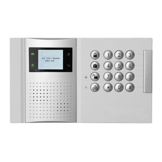
Arm Away
2 0 / 1 2 / 2 0 1 0
1 5 : 3 0
Manufacturer: SHENZHEN LONGHORN SECURITY TECHNOLOGY CO., LTD
TH
ST
TH
Add:
THE 4 BUILDING, 1 FLOOR OF THE 5 BUILDING, NEW AND HIGH
TECHNOLOGY PARK, GUANGMING, WANDAIHENG, BAOAN SHENZHEN, CHINA
Postcode: 518106
Fax: +86-755-33265388
Website: http://www.csst-longhorn.com
E-mail: helen.p@csst.com
Telephone number:
+86-755-33265399
Advertisement
Table of Contents

Related Manuals for LONGHORN LHD8003


Summary of Contents for LONGHORN LHD8003
- Page 1 Arm Away 2 0 / 1 2 / 2 0 1 0 1 5 : 3 0 Manufacturer: SHENZHEN LONGHORN SECURITY TECHNOLOGY CO., LTD Add: THE 4 BUILDING, 1 FLOOR OF THE 5 BUILDING, NEW AND HIGH TECHNOLOGY PARK, GUANGMING, WANDAIHENG, BAOAN SHENZHEN, CHINA...
- Page 2 CREATING SECURITY SOLUTION...
-
Page 3: Installation Information
INSTALLATION INFORMATION PACKING LIST Description Quantity User Name Item User Address Control Panel Installer Name Keyfob Installation Company Wireless PIR Detector Installation Date Wireless Magnetic Switch Phone of Installation Company Power Adaptor Fax of Installation Company Installation Manual Accessory Bag Control Panel ID Control Panel Phone NO. -
Page 4: Table Of Contents
7.1.3. Disarm --------------------------------------------------------------------------------------------------- 25 TABLE OF CONTENTS 7.2. Arm/Disarm via Phone ------------------------------------------------------------------------------------------- 7.3. Arm/Disarm via SMS ---------------------------------------------------------------------------------------------- Chapter 1 : Introduction ------------------------------------------------------------------------ 7.4. Trigger Alarm via Keypad ---------------------------------------------------------------------------------------- Chapter 2 : Specifications --------------------------------------------------------------------- Chapter 8 : Programming ------------------------------------------------------------------------- Chapter 3 : Hardware Layout ------------------------------------------------------------------ 8.1. -
Page 5: Chapter 1: Introduction
Chapter 1: Introduction Chapter 3: Hardware Layout The aim of this section is to acquaint you with the various circuit boards that make up the system. Introduction: 3.1 Main Board Nowadays, homeowners want much more than a monitored security system. They prefer an alert system. This wireless alarm kit offers an innovative all-in-one solution with all aspects of security and The main board is the brain of the system. -
Page 6: Power Supply Board
3.2 Power Supply Board Chapter 4: System Installation It supplies power for main board and GSM module. Pls cut off the power, with both AC and DC power off 4.1 Pre-installation Planning Cable interface for power, connect with power supply board Before starting the installation procedure, it is worthwhile to draw a rough sketch of the building and Flat-cable interface for GSM module determine the required position for the control panel and each wireless device. -
Page 7: Installation Procedure
4.3.2 Power off and Inser t SIM Card steel reinforced concrete wall SIM card must be inserted for GSM or SMS alarm via GSM module. The AC power and battery must be cut- off for safe operation. Steps: 1. Plug the AC power adaptor and battery flat-cable. 2. - Page 8 2. AUX Power Output Terminal For N/C detector: For N/O detector: AUX supplies power output for wired detectors(AC Operated: 10-12V, Battery Operated: 6-8V, max N/C detector current: 100mA. It may cause abnormal working for wired detector under low battery). N/O detector 3.
- Page 9 4.3.5 Register Transmitters At first, stick “Installing Hole Drawing” on the location for control panel. Drive 4 screws on the fixed position (see Figure 11-1), and then hang the control panel directly on the screws(see Figure 11-2). While driving Transmitters refer to wireless devices such as detector, magnetic switch, siren and keyfob, etc. Only after the screws, please pay strict attention to the depth of screws to make sure easy hang and tamper switch enrolling...
- Page 10 5.1.1 Status LED standby mode, system status, time and date, or Arm Away banner are displayed on LCD. If system status is Power LED: Red means AC loss or low battery. Green means normal. abnormal, it will displayed as: 2 0 / 1 2 / 2 0 1 0 15:30 Arm LED: Red means armed.
- Page 11 5.3 Alar m Type and Way Alarm Display: The alarm will display with voice guide in the alarm List. Press the navigation key to select with “#” to There are two alarm type: instant alarm and delay alarm. query the event. If there are multiple alarm events, press the navigation key directly to check other Trigger 24-hour zones, instant alarm will occur.
-
Page 12: Keypad Lock And Unlock
5.4 Keypad Lock and Unlock Code Type Arm&disarm Enter PROG Code Set “PROG” in main menu Editable Clearable User code 2 If the code is input wrong, the voice will guide “Wrong code, please re-input!” and the LCD displays as: User code 3 User code 4 ①... - Page 13 For detailed system trouble and solution, please refer to following table: 6.1 Zone Type Description Trouble Solutions Low Battery Low power of battery Check the power connection timely. Valid or not Valid or not Exit Entry Zone Sound Mount position Type Valid or not Line Loss...
- Page 14 Chapter 7: Ar m/Disar m Operation Arm Away 2 0/ 1 2 / 2 0 1 0 7.1 Ar m/Disar m via Keypad or Keyfob 1 5 : 3 0 You can arm away, arm stay, disarm or panic help via keypad or keyfob. If CMS is connected with message send, and info except zone alarm is set to send, any operation like arm and disarm will be reported to CMS.
- Page 15 7.2 Ar m/Disar m via Phone 2. If under arm away, and with no alarm, press “Arm stay” on keypad, the voice will guide “Enter password before setting parameters!” You can enter arm stay status with code input or direct keyfob operation. It enables you to arm or disarm via telephone(DTMF).
- Page 16 With faulty operation or unexpected alarm occurs, user can “Cancel Alarm” in the menu. Thus the panel Chapter 8: Programming will issue a event cancel to CMS To cancel alarm: → 8.1 Access Programming 1. From the menu, select “Cancel Alarm” “...
- Page 17 Note : The default master code is 0808, which is strongly recommended to edit after installation. Installer Code Set The default duress code is 0809 which is strongly recommended to edit after installation. The Installer code grants access to the Programming menu and the Service menu. Note To set installer code: →...
-
Page 18: Event Log
Voice Phone Interface Set 1. Bypass one by one 2. WL. Zone 2 1. WL. Zone 1 It enables you to select PSTN or GSM as dialling way. WL. Zone 2 To set voice phone interface: 1. From the main menu, select “Phone Set” → “#” → “Voice Phone Set” → “#”. 3. -
Page 19: Service Option
Siren Test 8.3.7 Ser vice Option Set Time/Date Siren test is strongly recommended periodically for safety, which includes wired siren, wireless siren and built-in siren. Time and date must be set, or else the event log will be recorded with no time, arm or disarm may not be To test siren: realized, or system trouble will happen, voice guide will not work. -
Page 20: Programming Set
Version WL. Zone 3 Keyfob 1 Type: Entry/Exit Low Battery It enables you to query the version of the control panel. Activate Siren To query the version of panel: Low Battery TX Loss 1. From the menu, select “Service” → “#” → “Version” →... - Page 21 2. Use the navigation key to select the zone ending with “#”. 1. WL. Zone1 1. By Code Learn 1. WL Zone 1 1.WL. Zone 1 3. Then use navigation key to “Active” or “Mute” the siren ending with “#” Registered! Save? 4.
-
Page 22: Communication
To send for alarm: To set siren cut-off: 1. From the main menu, select Programming” “ → #”→ “ “ Comm.” →“#” → “ Comm. Account ” → “#”. 1. From the main menu, select “Programming”→ #”→ Device”→ #”→ Siren”→ #”→ Siren Cut-off(M)” “... - Page 23 To set call attempts: Control Panel ID 1. From the main menu, select “Programming”→ “#”→“Comm. ”→ “#”→ “Comm. Option”→ “#“→ “Call Attempts” iID address can be set for each control panel so that the CMS can identify. Different ID must be set for →...
-
Page 24: System Option
Dial Back To set exit delay: RP dial back is a security feature that helps ensure that remote programming is only performed by 1. From the main menu, select “ Programming”→ #” → “ “ System Option”→ #” → Exit Delay(S)” “... -
Page 25: Initialization
AC Power off Delay(M) PGM Trigger Activated by…… Disactivated…… The AC Loss Delay is the amount of time that has to elapse before an AC Loss report is sent to the central Zone 16 Alarm See above See above station. If AC power is restored before the event message is sent, the event message is cancelled and will Zone 17 Alarm See above See above... -
Page 26: Chapter 9: Telecontrol Via Phone Or Sms
Clear Users Clear User Codes deletes all programmed user codes and restores the default master and installer Pressing any key on control panel or phone during voice play may cause communication error. It codes and duress codes. is suggest to operate after voice. If the system is under programming, remote programming is not To clear users: Note available. -
Page 27: Send Sms For Alarm
◆“Arm away”: ◆“Arm/ Disarm Query ”: ID: 1234 Prog: Arm away Password0808Status Act:OK Password0808Armaway ID: 1234 ID: 1234 ID: 1234 ID: 1234 Prog: Arm away Prog: Arm away Prog: Arm stay Prog: Disarm Act:ERR Act:OK Act:OK Act:OK ◆“Arm stay”: ID: 1234 9.4 Send SMS for Alar m Prog: Arm stay Act:OK... -
Page 28: Chapter 10: Parameters
◆Service info send to CMS by SMS 10.3 GSM Module ID:1234 ● GSM working frequency EGSM900/1800 Zone: 002 362700002 ● <-106 RX sensitivity: Event: Service ● Current: Standby: <25mA RX: <75mA 3627 means the CID exit PROG, 002 means the operator code. 2010/04/10 19:12:17 Chapter 11: Troubleshooting Chapter 10: Parameters... -
Page 29: Zone Type
Appendix 1:System Default Parameters Chapter 12: War ranty and Limitations Setting Item Parameter Default Although it is an advanced and reliable security system, it does not offer absolute guaranteed protection 4-6 digits 0808 Master Code 4-6 digits 1234 against burglary, fire, or other troubles. The limitations are as follows: Installer Code 4-6 digits 0809... -
Page 30: Appendix 2: Menu Structure
Appendix 2:Menu Structure Require for installer code 1. Cancel Alarm Requre for master code Description Abbreviation Temp. Temporary 2. Stop. Comm. Trb. Trouble 3. Code Set Auto Time Auto Arm/DisarmTime 1. Master Code Wireless 2. Installer Code Comm. Communication 3. Duress Code Supp. - Page 31 (To) 1. Devices 7. Service 1. Set Time/Date 1. Auto Time 1 1. WL. Register 1. By Code Learn 1. Zone 2. Auto Arm/Disarm 2. Auto Time 2 2. By Code Input 3. Auto Time 3 3.Call back when arm/dis. 2.
- Page 32 Appendix 3: Communication Protocol and Codes Appendix 4: Ter m Definitions Table 1: Contact ID Event Code ◆ Detector: A facility that detects intrusion and abnormal state automatically via some electric or CID Code Definition physical methods and output switch signals or wireless signals to the system for disposal, then output Panic Alarm alarm signals, such as infrared detector, smoke detector, etc.
- Page 33 Appendix 5: Zone Type Setting Figure Type Bypass or not Zone NO. Installation Position -61-...
Need help?
Do you have a question about the LHD8003 and is the answer not in the manual?
Questions and answers