Table of Contents
Advertisement
OPERATIONS AND
MAINTENANCE MANUAL
For
Benning Power Electronics
SLIMLINE INVERTER
24VDC @ 500VA
48VDC @ 1000VA
(028-0009-004 Rev B)
SAVE THESE IMPORTANT
SAFETY INSTRUCTIONS
This manual contains important safety instruc-
tions that should be followed during installation
and maintenance of the Power System.
11120 Grader Street
Dallas, TX 75238
214-553-1444, Fax 214-553-1355
Advertisement
Table of Contents

Related Manuals for Benning Tebevert 500


Summary of Contents for Benning Tebevert 500
-
Page 1: Safety Instructions
OPERATIONS AND MAINTENANCE MANUAL Benning Power Electronics SLIMLINE INVERTER 24VDC @ 500VA 48VDC @ 1000VA (028-0009-004 Rev B) SAVE THESE IMPORTANT SAFETY INSTRUCTIONS This manual contains important safety instruc- tions that should be followed during installation and maintenance of the Power System. - Page 3 Congratulations and thank you for purchasing a Benning BLI Modular Inverter System. We at Benning are committed to supporting the needs of our customers by supplying the customer with the proper information and documentation needed to properly install and operate the Inverter System purchased.
- Page 4 Page left blank intentionally...
-
Page 5: Switch Mode, Single-Phase, Sine-Wave Inverter
Operating Instructions Switch mode, single-phase, sine-wave Inverter Product line TEBEVERT Series TEBEVERT 500 and TEBEVERT 1000 (19”/3.5”, with mechanical transfer relay, DSP technology) Date Designation No. 4219en R2 Issued: August 8, 2005 Page 1/22pages Revision Checked... - Page 6 Switch mode, single-phase, sine-wave Inverter Product line TEBEVERT Page left blank intentionally August 8, 2005 - DTL 2/21 No. 4219en R2...
-
Page 7: Table Of Contents
Switch mode, single-phase, sine-wave Inverter Product line TEBEVERT Table of contents Safety notes ....................6 General ...................... 7 Inverter ...................... 8 Design of the unit ..................9 Terminals and operating elements ............10 Technical data ..................12 Assembly and commissioning ..............16 Device settings .................. - Page 8 For more detailed information call our service centre under phone +1 214 553 1444 In addition, our helpdesk team is 24 hours per day at your disposal for technical support under phone +1 800 910 3601 BENNING Power Electronics, Inc. 11120 Grader St. Dallas, TX 75238 214-553-1444 www.benning.us...
- Page 9 Switch mode, single-phase, sine-wave Inverter Product line TEBEVERT Explanation of the symbols used: Indicates safety instructions which must be followed to avoid danger to persons! Indicates instructions which must be followed to avoid material damage! All specifications in these operating instructions must be observed at all times! General instructions which must be observed Further symbols and pictograms are explained at the appropriate places in the...
-
Page 10: Safety Notes
Switch mode, single-phase, sine-wave Inverter Product line TEBEVERT Safety notes The inverter is an electronic device which operates at dangerous voltage and current levels. For this reason, the following instructions must be followed at all times! The inverter should be installed, operated, repaired and maintained in accordance with the instructions in this document. -
Page 11: General
Switch mode, single-phase, sine-wave Inverter Product line TEBEVERT General The inverters in the product line TEBEVERT with an integrated switch-over device can be utilized for a wide range of applications in the field of telecommunications and other applications. The output power of the inverter is either 500VA with 24VDC input models or 1000VA with 48VDC input models. -
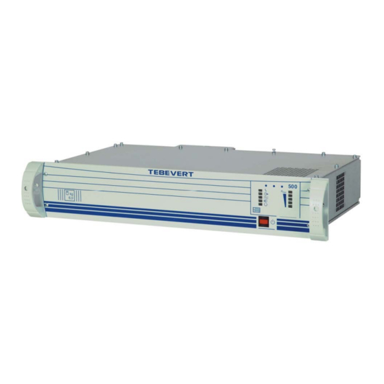
Page 12: Inverter
Switch mode, single-phase, sine-wave Inverter Product line TEBEVERT Inverter The DC input voltage of 24VDC or 48VDC (depending on the model) is converted inside the inverter to an AC voltage of 120VAC and 60Hz. Fig. 1: Inverter outline August 8, 2005 - DTL 8/21 No. -
Page 13: Design Of The Unit
Switch mode, single-phase, sine-wave Inverter Product line TEBEVERT Dimensions of the unit Millimeter Inches 3.07” 10.82” 19” 466.2 18.35” 17.32” 88.1 3.47” Fig. 2: Dimension diagram of the inverter August 8, 2005 - DTL 9/21 No. 4219en R2... -
Page 14: Terminals And Operating Elements
All operating elements are located on the front, installer connections are found on the rear the inverter. Fig. 3: Front view of the inverter TEBEVERT 500 Unit switch ON/OFF The inverter can be switched on and off with this push button switch. - Page 15 Switch mode, single-phase, sine-wave Inverter Product line TEBEVERT LED’s for signalling the actual inverter output power The inverter is overloaded if the LED is flashing (RED) When this LED is lit the inverter is loaded nearly to the limit (YELLOW) The lit LED’s indicate the approximate load level (Green) Fig.
- Page 16 Switch mode, single-phase, sine-wave Inverter Product line TEBEVERT X5; potential free central fault signal X5:1-2 fault X5:1-3 no fault X1(-); Copper bar / threaded stud; negative (-) connection for the DC input of the inverter. Arranged for ¼” x 5/8”, two-hole crimp lug threaded stud;...
-
Page 17: Technical Data
Switch mode, single-phase, sine-wave Inverter Product line TEBEVERT Technical Data DC input: DC voltage: 24 VDC (48 VDC) Permissible deviation from rated value: +20%; -15% Input current at rated real power Nominal input voltage 100%: 19.8 A (19.0 A) Over voltage 120%: 16.3 A (16.0 A) Under voltage 85%: 22.6 A (22.5 A) - Page 18 Switch mode, single-phase, sine-wave Inverter Product line TEBEVERT Crest factor: 2.8; @ 120V/4.2A (@120V/8.3A) maximum peak current 2.8xI with larger crest factor the permissible rms. current is less Frequency: 60 Hz (50Hz option) Frequency stability: ±0.1% inverter operation Harmonic distortion factor: with linear load ≤3% Permissible power factor:...
- Page 19 Switch mode, single-phase, sine-wave Inverter Product line TEBEVERT Load fuse: The short circuit current can blow slow fuses with of the nominal current rating. Radio interference degree: Class B (EN 55022) Switch-over device: Mechanical contactor Switching times: ≤ 100 ms Switching thresholds of the input voltage monitoring: Setting parameter Default settings...
-
Page 20: Assembly And Commissioning
Switch mode, single-phase, sine-wave Inverter Product line TEBEVERT Assembly and commissioning Attention! The safety instructions must be observed at all times during assembly, installation and commissioning! After installation, connecting and commissioning the inverter is ready for operation without restriction. No additional settings and readjustments are necessary during operation under all operating conditions. - Page 21 Plug customer load into receptacle X3; X4 (NEMA 5-15 R ) Optional - Plug Commercial AC bypass (if required) into the inlet X2 (IEC/EN 60320-1) Benning Pt. No. 220-1000-102, IEC-320-14 line cord, 7’-6” long. Connect the potential free central alarm to X5;1, 2 or 3 as required, screw terminals (M2) •...
-
Page 22: Installation Of The Unit
Switch mode, single-phase, sine-wave Inverter Product line TEBEVERT Installation of the unit Attention! The inverter should be free of voltage before installation. Neither the commercial AC bypass nor the DC supply should be connected and must be disconnected if they were connected. The inverter may be mounted in two different manners. -
Page 23: Maintenance / Repair
Switch mode, single-phase, sine-wave Inverter Product line TEBEVERT Switch on the DC supply by closing/inserting the disconnecting device ⇒ The LED is lit (this indicates the DC input voltage is within the acceptable input range) Switch on the inverter by pressing the ON/OFF switch. ⇒... -
Page 24: Description Of Function
Switch mode, single-phase, sine-wave Inverter Product line TEBEVERT Description of function The inverters are set at the factory to "inverter priority". In normal operation the AC voltage produced by the inverter from the DC input voltage is available at the load receptacles. -
Page 25: Appendix
Switch mode, single-phase, sine-wave Inverter Product line TEBEVERT Appendix A Block diagram of the inverter August 8, 2005 - DTL 21/21 No. 4219en R2... - Page 26 Switch mode, single-phase, sine-wave Inverter Product line TEBEVERT WALL Floor Millimeter Inches 7.09” 21.46” 20.24” Figure 5, Wall inserts and/or wall mounting screw placement and proper orientation of the Inverter against the wall. August 8, 2005 - DTL 22/21 No. 4219en R2...
Need help?
Do you have a question about the Tebevert 500 and is the answer not in the manual?
Questions and answers