Table of Contents
Advertisement
Quick Links
Operations and Maintenance Manual
Benning Power Electronics
1220 Presidential Drive Suite 100
Richardson, TX 75081 USA
www.benning.us
Tebevert I I I 25k VA
800.910.3601
120VDC I nverter System
This manual contains important
safety instructions that should be
028-0009-006 Rev. C
followed during installation and
maintenance of the Power
System.
Advertisement
Table of Contents

Subscribe to Our Youtube Channel
Related Manuals for Benning Tebevert III


Summary of Contents for Benning Tebevert III
- Page 1 Operations and Maintenance Manual Benning Power Electronics 1220 Presidential Drive Suite 100 Richardson, TX 75081 USA www.benning.us Tebevert I I I 25k VA 800.910.3601 120VDC I nverter System This manual contains important safety instructions that should be 028-0009-006 Rev. C...
-
Page 3: Table Of Contents
TABLE OF CONTENTS IMPORTANT INFORMATION ........................i VERSION ..........................i PASSWORD .......................... ii DATA SHEET ........................iii PREFACE ..........................1 SAFETY NOTES AND MARKINGS ..................3 GENERAL ..........................6 THE COMPONENTS OF THE TYPICAL INVERTER SYSTEM ..........6 PSJ TYPE EQUIPMENT CABINET ..................7 INVERTER SLOTS ....................... - Page 4 4.3.3 AC CABLE REQUIREMENTS FOR 25kVA, 120 VAC AC INPUT RATINGS......35 4.3.4 AC CABLE REQUIREMENTS FOR 25kVA, 120/240 VAC INPUT SYSTEM....... 35 4.3.5 AC CABLE REQUIREMENTS FOR 25kVA, 208 VAC INPUT SYSTEM........35 4.3.6 AC CABLE REQUIREMENTS FOR 25kVA, 220 VAC INPUT SYSTEM ........36 4.3.7 AC CABLE REQUIREMENTS FOR 25kVA, 240 VAC INPUT SYSTEM ........
-
Page 5: Version
All rights are reserved. No part of this manual may be photocopied, reproduced, or translated to another language without prior written consent of Benning Power Electronics. Specifications in this manual are subject to change without notice. -
Page 6: Password
PASSWORD: Password Level 1: PW 1 Password Level 2: PW 2 Password Level 3: PW 3 Password Level 4: PW 4 NOTE: PUT A SPACE BETWEEN PW AND THE NUMBER... -
Page 7: Key Features
TEBEVERT III MODULAR 5-25 kVA INVERTER SYSTEM The TEBEVERT III Modular Inverter System is designed to address the critical AC powering requirements of Industrial and Utility applications. The TEBEVERT III Modular Inverter System can be scaled in 5 kVA increments up to 25 kVA (non-redundant). Unlike... -
Page 8: Technical Specifications
41.6A Benning Power Electronics, Inc. Toll Free: 800.910.3601 11120 Grader St . Dallas . TX 75238 Outside the US: 214.553.1444 E-Mail: sales@benning.us Fax: 214.553.1355 WEB:www.benning.us Tebevert III_120 (R1_07) © Benning Power Electronics 2007 Specifications are subject to change without notice... -
Page 9: Preface
Congratulations and thank you for purchasing a Benning TEBEVER T I I I I nverter System ! We at Benning are committed to supporting the needs of our customers by supplying the customer with the proper information and documentation needed to properly install and operate the unit purchased. - Page 10 TEBEVERT III INVERTER SYSTEM (120 VDC) Switched-Mode Modular Series TEBEVERT (HOT-PLUG-Version) Inverter System Model: 5.0kVA-25.0kVA (120VDC Input, 120 VAC Output Modules) 07.11.2011 028-0009-006...
-
Page 11: Safety Notes And Markings
TEBEVERT III INVERTER SYSTEM (120 VDC) SAFETY NOTES AND MARKINGS This operating manual contains important information for the installation, operation, and maintenance of the inverter system. This manual must be retained and observed at all times! Explanation of the symbols used:... - Page 12 TEBEVERT III INVERTER SYSTEM (120 VDC) Further symbols, diagrams and pictures are explained at the appropriate places within this operating manual. Explanation of the abbreviations and definitions used: Static By-Pass Switch (SBS) Digital volt-ammeter Mains Commercial AC input power source...
- Page 13 TEBEVERT III INVERTER SYSTEM (120 VDC) The inverter system is an electrical unit with dangerous voltage and current levels. For this reason, the following safety instructions must be observed. Installation, operation, maintenance, and repair should be carried out in strict accordance with the instructions in this document.
-
Page 14: General
AC current and satisfies the highest requirements with respect to the expansion of the system, ease of maintenance and operating safety. The TEBEVERT III is available for DC voltages of 120VDC. Each inverter module is available in 5.0kVA/4.0kW. Parallel operation of maximum of five (5) inverter modules provides a maximum system rating of 25.0kVA/20kW. -
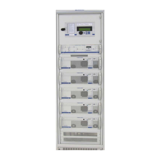
Page 15: Psj Type Equipment Cabinet
PSJ TYPE EQUIPMENT CABINET The Benning TEBEVERT III system is built and supplied into a 19” PSJ type, fully enclosed, floor standing cabinet (23.6” X 23.6” X 7’0” outside overall dimension). Cabinets are available for New Equipment building Standards (NEBS) and non-NEBS applications. - Page 16 TEBEVERT III INVERTER SYSTEM (120 VDC) Input Terminals and distribution position (depending on the application) Static By-Pass Switch (SBS) shelf Inverter module shelf 5 (A5) Inverter module shelf 4 (A4) Inverter module shelf 3 (A3) Inverter module shelf 2 (A2)
- Page 17 TEBEVERT III INVERTER SYSTEM (120 VDC) Manual by-pass switch (Q10) SBS module (A6) Inverter Module 5 ( A5 ) Inverter Module 4 ( A4 ) Inverter Module 3 ( A3 ) Inverter Module 2 ( A2 ) Inverter Module 1 ( A1 )
- Page 18 TEBEVERT III INVERTER SYSTEM (120 VDC) TYPICAL INPUT/OUTPUT TERMINALS FOR AN INDIVIDUAL FEED CONFIGURATION Figure 3 TYPICAL SNMP OPTION Figure 4 07.11.2011 028-0009-006...
- Page 19 TEBEVERT III INVERTER SYSTEM (120 VDC) INVERTER MODULE SHELF • Data line factory connected to the next inverter slot or the SBS slot (X1) • Data connector for the inverter connection (X3) • Load connector for the AC connection of the inverter output (X6) 3 poles (2.5kVA) 5 poles (5.0kVA)
-
Page 20: Sbs Slot
TEBEVERT III INVERTER SYSTEM (120 VDC) SBS MODULE SHELF • Terminal block for the connection of the auxiliary DC supply to the SBS (X26) • Terminal block for the voltage-free collective fault messaging system of the inverter system (X25) • Terminal block for the connection of the auxiliary contact signifying the by- pass switch is in the “manual by-pass inverter”... -
Page 21: Inverter Slots
TEBEVERT III INVERTER SYSTEM (120 VDC) • Female connector for the protective earth of the SBS ( ) • Female connector for the mains input (L1) • Female connector for the SBS output and the inverter output (N) • Female connector for the SBS output (L) •... - Page 22 TEBEVERT III INVERTER SYSTEM (120 VDC) 3. 4 MANUAL MAINTENANCE BY-PASS SWITCH Fig. 5: Manual Maintenance By-pass Switch Q10 The manual maintenance by-pass switch is mechanically connected to both the SBS slot and the SBS itself. The locking mechanism prevents the SBS from being pulled out of the inverter system unless it has been switched to the proper position, Position “1”...
-
Page 23: Inverter
TEBEVERT III INVERTER SYSTEM (120 VDC) INVERTER The inverter converts the incoming nominal DC voltage of 120VDC into AC voltage of 120VAC, 50 or 60Hz. (Refer to Section 4.3.x for specific wiring details) I m portant Note! The 120/240VAC configuration utilizes input/output transformers to convert the input and output voltages from the nominal 120VAC. - Page 24 TEBEVERT III INVERTER SYSTEM (120 VDC) Fig. 6: Diagram of the modular inverter unit 07.11.2011 028-0009-006...
-
Page 25: Terminals And Operating Units
TEBEVERT III INVERTER SYSTEM (120 VDC) 3.5.2 TERMINALS AND OPERATING ELEMENTS All terminals and operating elements are installed on the front or rear of the inverter module. Fig. 7: Front view of the inverter weight notice of the individual plug-in unit... - Page 26 TEBEVERT III INVERTER SYSTEM (120 VDC) Fig. 8: Rear view of the modular inverter unit Data connector (X3) DIP switch to set the frequency (S2) (Refer to Section 4.1 for details) Contact blade for the protective earth (X1: Contact blade for the DC input (X1:...
-
Page 27: Signalling
TEBEVERT III INVERTER SYSTEM (120 VDC) 3.5.3 SIGNALLING On the front panel of the inverter there is a bar graph indicator and LED´s that are used to indicate the operating state of the inverter. Fig. 9: Operating and signalling panel This symbol indicates that all the points in this operating manual must be observed at all times. - Page 28 TEBEVERT III INVERTER SYSTEM (120 VDC) Color Meaning when LED lights up The output voltage of the inverter is normal. (V 120 or 120/240V) See note Important Note below. green "OUTPUT VOLTAGE PRESENT" The output voltage of the inverter is in phase and...
-
Page 29: Electronic Switch-Over Sbs Unit
TEBEVERT III INVERTER SYSTEM (120 VDC) STATIC BY-PASS SWITCH (SBS) UNIT The static by-pass switch (SBS) unit monitors the AC bypass input and DC input. The Inverter System operates primarily on DC and transfers to Ac automatically upon DC failure. The maintenance bypass switch should remain in position “0”... -
Page 30: Design Of The Unit
TEBEVERT III INVERTER SYSTEM (120 VDC) 3.6.1 DESIGN OF THE UNIT Fig. 10: Diagram of the static by-pass switch (SBS) 07.11.2011 028-0009-006... -
Page 31: Terminals And Operating Elements
TEBEVERT III INVERTER SYSTEM (120 VDC) 3.6.2 TERMINALS AND OPERATING ELEMENTS All terminals and operating elements are on the front panel or rear of the SBS unit. Fig. 11: Front view of the Static By-Pass Switch (SBS) Display and signalling panel... - Page 32 TEBEVERT III INVERTER SYSTEM (120 VDC) X 3 X 4 Fig. 12: Rear view of the Static By-Pass Switch (SBS) Contact blade for the protective earth (X1: Contact blade for the SBS output (X1: N) Contact blade for the inverter input (X1: 1L) Female connector for the data bus (X3;...
-
Page 33: Signalling
TEBEVERT III INVERTER SYSTEM (120 VDC) 3.6.3 SIGNALLING On the front panel of the SBS module there is a digital volt/ammeter and various LED´s, used to indicate the operating state of the SBS unit. Fig. 13: Display and signalling panel... -
Page 34: Acd Distributin Panel
AC DISTRIBUTION PANEL External AC electrical panels are recommended. These can be sourced from your local electrical supplier Benning. Two additional AC distribution options can be used with the inverter cabinet. One utilizes a standard North American style snap-in breaker and the other utilizes standard DIN style breakers. -
Page 35: Din Rail Style Breaker Panel
TEBEVERT III INVERTER SYSTEM (120 VDC) 3.7.2 DIN RAIL STYLE BREAKER PANEL This AC Distribution option is an internally mountable option. The panel is designed to accommodate up to 24 breaker positions using standard CBI type QL, UL Listed, 1 or 2-pole, DIN Rail mounting circuit breakers. The maximum allowable sized breaker is 25A per pole. -
Page 36: Installation And Commissioning
TEBEVERT III INVERTER SYSTEM (120 VDC) INSTALLATIN AND COMMISSIONING After assembly, installation and commissioning of the inverter system, all components are ready for operation. No additional settings and adjustments are necessary. W arning! The safety instructions must be observed at all times during assembly, installation and commissioning. -
Page 37: Inverter Settings
TEBEVERT III INVERTER SYSTEM (120 VDC) INVERTER SETTINGS Each inverter is set to factory default values according to the required operating conditions. (See Chapter 3.7 / Technical data or the specification sheet) An adjustment of these settings is not usually necessary. -
Page 38: Settings Of The Electronic Switch -Over/Sbs Unit
TEBEVERT III INVERTER SYSTEM (120 VDC) SETTINGS OF THE STATIC BY-PASS SWITCH (SBS) The Static By-Pass Switch (SBS) is factory set to default values. (See Chapter 3.7 / Technical data or the specification sheet). It is not usually necessary to change these settings. - Page 39 TEBEVERT III INVERTER SYSTEM (120 VDC) Adjustments Position 1 Position 0 Operating mode inverter priority mains priority Nominal voltage 120 or 120/240 V 230 V Nominal frequency 50 Hz 60Hz Mains error signal no mains available operation with (no mains failure...
-
Page 40: Panel Writing
TEBEVERT III INVERTER SYSTEM (120 VDC) PANEL WRITING The cable is fed into the inverter system from above or below, according to the model. The size and location of the terminal blocks and distribution assemblies are configuration dependant, refer to Elevation drawing for exact requirements. - Page 41 TEBEVERT III INVERTER SYSTEM (120 VDC) W arning! For the proper protection of the load circuits careful attention must be paid to the selection of upstream the mains protection. The voltage-free fault messaging contact are rated for a maximum of 230VAC/1A or 270VDC/0.2A (50W max).
-
Page 42: Block)
TEBEVERT III INVERTER SYSTEM (120 VDC) 4.3.1 DC CABLE REQUIREMENTS FOR 25kVA, 120 VDC INDIVIDUAL DC INPUT (DIN RAIL OR BUSBAR TERMINAL BLOCK) Terminal Connection Terminal/connection Suggested designation type capacity protection Compression Type X1: 1L+/1L- 50A/8 AWG input/inverter 1 2AWG – 4/0... -
Page 43: Ac Cable Requirements For 25Kva, 120Vac Ac Input Ratings
TEBEVERT III INVERTER SYSTEM (120 VDC) 4.3.3 AC CABLE REQUIREMENTS FOR 25kVA, 120VAC AC INPUT RATINGS Maximum system Suggested rating of Supply conductor capacity disconnect device Mains 5 inverters 120VAC/250A Terminal Connection Terminal/connection Suggested designation type capacity protection Compression Type... -
Page 44: Ac Cable Requirements For 25Kva, 220 Vac Input System
TEBEVERT III INVERTER SYSTEM (120 VDC) 4.3.6 AC CABLE REQUIREMENTS FOR 25kVA, 220VAC AC INPUT SYSTEM Maximum system Suggested rating of Supply conductor capacity disconnect device Mains 5 inverters 220VAC /150A Terminal Connection Terminal/connection Suggested designation type capacity protection Compression Type... -
Page 45: Torque Table For All Terminations
TEBEVERT III INVERTER SYSTEM (120 VDC) 4.3.9 TORQUE TABLE FOR ALL TERMINATIONS Terminal Block Torque Table Terminal in-lb ft-lb P/N# UKH95 177.01 14.75 UKH150 265.52 22.12 Stud Terminal Torque Table 07.11.2011 028-0009-006... -
Page 46: Installation Of The Units
TEBEVERT III INVERTER SYSTEM (120 VDC) 4.4 INSTALLATION OF THE UNITS Prior to the installation of the Static By-Pass Switch (SBS) and the inverters in the inverter system, the following points must be checked and observed. • Verify that the units are of the same type and model (120VDC / 120VAC) Since all inverters of this series are identical for the user, the exact model of the unit must be checked. -
Page 47: Installation Of The Static By-Pass Switch (Sbs)
TEBEVERT III INVERTER SYSTEM (120 VDC) 4.4.1 INSTALLATION OF THE STATIC BY-PASS SWITCH (SBS) At the time the Static By-Pass Switch (SBS) is installed, the operating handle of the manual maintenance by-pass switch is attached. The handle is installed on top of the SBS unit using supplied four (4) M4 x 8mm screws. -
Page 48: Installation Of The Inverters
TEBEVERT III INVERTER SYSTEM (120 VDC) 4.4.2 INSTALLATION OF THE INVERTERS W arning! The weight of each inverter is approx. 35kg (77lbs). The unit may only be lifted and transported using the carrying handles built into each side of the unit. DO NOT carry or... - Page 49 TEBEVERT III INVERTER SYSTEM (120 VDC) The AC by-pass is connected to the output and the DVA shows the AC by- pass voltage (e.g. 120), if the selector switch underneath the DVA is in the position "V". The first inverter can now be switched on. After a start-up time of approx.
-
Page 50: Performance Testing
Fig. 16: LED states of the inverter (normal operation) PERFORMANCE TESTING • The following load test is recommended by a Benning technician. PRELIMINARIES TO PERFORMANCE TEST The site manager must be informed of the test to be performed, and that alarms will be sent (if connected) to the central alarm center or Network Operations Center. -
Page 51: Test Equipment
TEBEVERT III INVERTER SYSTEM (120 VDC) TEST EQUIPMENT • A suitable voltmeter with measuring range 250 VAC, 100 mV and 60 VDC. • A clamp-on ammeter capable of measuring 250Amps AC. • A load bank capable of supplying 26,000 W. - Page 52 TEBEVERT III INVERTER SYSTEM (120 VDC) Action Result modules) The internal temperature will rise and the inverter module will automatically switch off. Disconnect the load bank and re-start The green LEDs “OUTPUT VOLTAGE the inverter by means of the On/Off AVAILABLE”...
-
Page 53: Test Of The Sbs Unit
TEBEVERT III INVERTER SYSTEM (120 VDC) TEST OF THE SBS UNIT Make sure the system is in the following state: • Disconnect the load from the inverter system. • Connect the load bank to the output of the inverter system. -
Page 54: Sbs Test Activities
TEBEVERT III INVERTER SYSTEM (120 VDC) 5.4.1 SBS TEST ACTIVITIES Action Result Switch off the mains from the by-pass. The green LED “MAIN VOLTAGE AVAILABLE” and “READY FOR OPERATION” go out and the red LED “FAULT” lights up. Also an outgoing alarm shall be given after approximately 10 seconds. -
Page 55: Final Steps
TEBEVERT III INVERTER SYSTEM (120 VDC) 5.5 FINAL STEPS • Disconnect any test equipment that has been connected to the system and make sure that materials that do not belong in the equipment have been removed. • Restore the equipment to its original condition. Make sure the cabinet is placed so that cooling air has free access. - Page 56 TEBEVERT III INVERTER SYSTEM (120 VDC) Position 0: UPS operation Position 1: Load on Reserve Input Position 2: Load on Inverter Output Prior to operating the manual maintenance by-pass switch verify the SBS is operating in one of the following modes. Failure to do so could result in...
- Page 57 TEBEVERT III INVERTER SYSTEM (120 VDC) After the servicing work is complete (exchange of the SBS, work on the supply mains) and if the system is in proper working order, the manual by-pass switch can be turned back to position 0 (UPS operation).
-
Page 58: Exchange Of Units
TEBEVERT III INVERTER SYSTEM (120 VDC) EXCHANGE OF UNITS Exchange of an inverter In this case, the manual by-pass switch does not need to be used. However, if this is desired for any reason, the manual by-pass switch must be switched to position 1 (Load on By-pass Input). -
Page 59: Upgrading The System
TEBEVERT III INVERTER SYSTEM (120 VDC) Removal of the SBS: After the manual by-pass switch has been turned to position 1 or 2, the 4 retaining screws are removed and the SBS is pulled out of the front of the cabinet. -
Page 60: Inverter
TEBEVERT III INVERTER SYSTEM (120 VDC) The inverter system supplies a high availability AC current supply to load equipment that must have an uninterrupted input power supply at all times. According to the selected operating mode, the inverter output voltage (inverter priority) or the mains voltage (mains priority) is switched through to the load equipment by the SBS. - Page 61 TEBEVERT III INVERTER SYSTEM (120 VDC) EIN/ AUS/ Under voltage Over Voltage 1 Under voltage range Over voltage range Fig. 17: Switching thresholds for over voltage and under voltage monitoring system Figure 17 shows the main principles of the system. If over voltage is applied, the inverter switches off at U2.
-
Page 62: Monitoring The Output Voltage
TEBEVERT III INVERTER SYSTEM (120 VDC) 7.2.2 MONITORING THE OUTPUT VOLTAGE The output voltage supplied by the inverter is also monitored. If the output volta ge is within the ra nge 120 10% (108V ... 132V), this ta rge te d state is indicated by an LED on the front panel. -
Page 63: Short-Circuit Behavior
TEBEVERT III INVERTER SYSTEM (120 VDC) 7.2.5 SHORT-CIRCUIT BEHAVIOR The inverter is permanently short-circuit proof. Short-circuits are a special type of overload. At the time of the short-circuit, the current is limited for 5 seconds to 2.8 times the nominal effective current. During this period, the short-circuit current can trigger the AC load protection circuits in the customer provided AC distribution.. - Page 64 TEBEVERT III INVERTER SYSTEM (120 VDC) disturbances in the AC by-pass supply disturbances in the inverter / inverter system disturbances in the SBS The reset of the dry contact alarm relay occurs without a delay. To permit operation of the SBS via the remote monitoring system MCU, an additional unit (satellite card) must be installed.
- Page 65 TEBEVERT III INVERTER SYSTEM (120 VDC) From Version 1.03 on we support a redundancy function generating two events in the SBS satellite. This can be mapped to an input of the optional MCU and used to control alarm relays in the relay box Option.
- Page 66 TEBEVERT III INVERTER SYSTEM (120 VDC) Notes 07.11.2011 028-0009-006...
- Page 67 TEBEVERT III INVERTER SYSTEM (120 VDC) Notes 07.11.2011 028-0009-006...
- Page 68 TEBEVERT III INVERTER SYSTEM (120 VDC) Notes 07.11.2011 028-0009-006...
- Page 70 Benning Power Electronics 1220 Presidential Drive Suite 100 Richardson, TX 75081 USA www.benning.us 800.910.3601 This manual contains important safety instructions that should be followed during installation and maintenance of the Power System.
Need help?
Do you have a question about the Tebevert III and is the answer not in the manual?
Questions and answers