Advertisement
Table of Contents
- 1 Table of Contents
- 2 Safety Notes
- 3 General
- 4 Inverter
- 5 Dimensions of the Unit
- 6 Terminals and Operating Elements
- 7 Technical Data
- 8 Assembly and Commissioning
- 9 Device Settings
- 10 Connecting the Inverter
- 11 Installation of the Unit
- 12 Commissioning the Inverter
- 13 Maintenance / Repair
- 14 Description of Function
- 15 Configuration Index
- Download this manual
Advertisement
Table of Contents

Related Manuals for Benning DSP 2500


Summary of Contents for Benning DSP 2500
- Page 1 Operations and Maintenance Manual Benning Power Electronics 11120 Grader Street Dallas, TX 75238 USA 214.553.1444 800.910.3601 DSP 2500 This manual contains Inverter System important safety instructions that should be followed during 028-0009-200 installation and maintenance of the Power System.
- Page 3 Congratulations and thank you for purchasing a Benning DSP 2500 Inverter System. We at Benning are committed to supporting the needs of our customers by supplying the customer with the proper information and documentation needed to properly install and operate the unit purchased.
- Page 4 Proprietary Information: This manual contains proprietary information which is protected by copyright law. All rights are reserved. No part of this manual may be photocopied, reproduced, or translated to another language without prior written consent of Benning Power Electronics. Specifications in this manual are subject to change without notice.
-
Page 5: Table Of Contents
Table of Contents 1. SAFETY NOTES ...................... 2 2. GENERAL ........................ 3 3. INVERTER ....................... 4 4. DIMENSIONS OF THE UNIT..................5 Fig. 1: Dimension diagram of the DSP Inverter ............5 5. TERMINALS AND OPERATING ELEMENTS ............6 Fig. 2: Front view of the DSP Inverter ..............6 Fig. - Page 6 DSP 2500 Inverter System Explanation of the symbols used: Indicates safety instructions which must be followed to avoid danger to persons! Indicates instructions which must be followed to avoid material damage! All specifications in these operating instructions must be observed at all times! ...
-
Page 7: Safety Notes
DSP 2500 Inverter System 1. Safety Notes The inverter is an electronic device which operates at dangerous voltage and current levels. For this reason, the following instructions must be followed at all times! 1. The inverter should be installed, operated, repaired and maintained in accordance with the instructions in this document. -
Page 8: General
DSP 2500 Inverter System 2. General The inverters in the DSP can be utilized for a wide range of applications in the field of telecommunications and other applications. The output power of the inverter is 2500VA with 48VDC input model. The inverters utilize Digital Signal Processor (DSP) technology, programmed with the appropriate algorithms to carry out control and monitoring of the inverter. -
Page 9: Inverter
DSP 2500 Inverter System 3. Inverter The DC input voltage of 48 VDC is converted inside the inverter to an AC voltage of 120, 240 or 120/240VAC at 60Hz. 10.15.07 028-0009-200... -
Page 10: Dimensions Of The Unit
DSP 2500 Inverter System 4. Dimensions of the Unit Fig. 1: Dimension diagram of the DSP Inverter 10.15.07 028-0009-200... -
Page 11: Terminals And Operating Elements
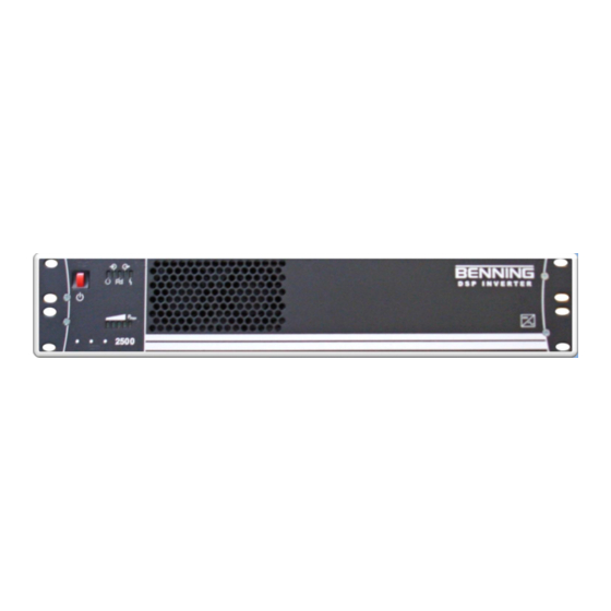
DSP 2500 Inverter System 5. Terminals and Operating Elements All operating elements are located on the front, installer connections are found on the rear the inverter. Fig. 2: Front view of the DSP Inverter Unit switch ON/OFF LED’s for indicating the inverter status... - Page 12 DSP 2500 Inverter System LED’s for signalling the actual inverter output power The inverter is overloaded if the LED is flashing (RED) When this LED is lit the inverter is loaded nearly to the limit (YELLOW) The lit LED’s indicate the approximate load level.
- Page 13 DSP 2500 Inverter System Fig. 3: Rear view of the DSP inverter (+); Copper bar / threaded stud; plus (+) connection for the DC input of the inverter. Arranged for ¼” x 5/8”, two-hole crimp lug (-); Copper bar / threaded stud; negative (-) connection for the DC input of the inverter.
-
Page 14: Technical Data
DSP 2500 Inverter System 6. Technical Data Tebevert DSP (2500VA @ 120VAC) The inverter module features DSP controlled high frequency, switch mode PWM technology. The module converts the incoming DC voltage to computer grade 120VAC 60Hz power for use by the connected customer equipment. - Page 15 DSP 2500 Inverter System Frequency stability: 0.1% crystal controlled Distortion factor: 2% at linear load Permissible power factor: cos = 0.7 ind. to cos = 0.8 cap. Efficiency at nominal real power: > 88 % Internal output fuse: T30A/250V Physical/Environmental Weight: 30 lbs.
- Page 16 DSP 2500 Inverter System Three NEMA Output receptacles protected by a 20A push to reset circuit breaker One 120VAC Bulk Terminal Block Output (L, N, G) protected by a single-pole 30A rocker style breaker Parallel Module Option: Dual RJ-45 receptacles and 120VAC Bulk Terminal...
- Page 17 DSP 2500 Inverter System Tebevert DSP (2500VA @ 240VAC) The inverter module features DSP controlled high frequency, switch mode PWM technology. The module converts the incoming DC voltage to computer grade 240VAC 60Hz power for use by the connected customer equipment.
- Page 18 DSP 2500 Inverter System Frequency stability: 0.1% crystal controlled Distortion factor: 2% at linear load Permissible power factor: cos = 0.7 ind. to cos = 0.8 cap. Efficiency at nominal real power: > 88 % Internal output fuse: T15A/250V Physical/Environmental Weight: 30 lbs.
- Page 19 DSP 2500 Inverter System One 240VAC Bulk Terminal Block Output (L1, L2, G) protected by a double-pole 20A rocker style breaker Parallel Module Option: Dual RJ-45 receptacles and 240VAC Bulk Terminal Block Input (L1, L2, G) for parallel unit operation...
- Page 20 DSP 2500 Inverter System Tebevert DSP (120/240VAC @ 2500VA) The inverter module features DSP controlled high frequency, switch mode PWM technology. The module converts the incoming DC voltage to computer grade 120/240VAC 60Hz power for use by the connected customer equipment.
- Page 21 DSP 2500 Inverter System Frequency stability: 0.1% crystal controlled Distortion factor: 2% at linear load Permissible power factor: cos = 0.7 ind. to cos = 0.8 cap. Efficiency at nominal real power: > 88 % Internal output fuse: T30A/250V Physical/Environmental Weight: 30 lbs.
- Page 22 DSP 2500 Inverter System Three NEMA output receptacles protected by a 20A push to reset circuit breaker Two – Three (TBD) IEC 320 output receptacles protected by a 15A push to reset circuit breaker One 120/240VAC Bulk Terminal Block Output (L1, N,...
-
Page 23: Assembly And Commissioning
DSP 2500 Inverter System Switching thresholds of the input voltage monitoring: Rated input voltage 48 V DC Lower switch-off threshold U1 40.8 V Switch-on threshold U2 49.0 V Switch-on threshold U3 57.6 V Upper switch-off threshold U4 60.0 V The Inverter can be switched on only when the input voltage is UDC≥U2. -
Page 24: Device Settings
DSP 2500 Inverter System 8. Device Settings Attention! No adjustments are necessary for normal operation. 9. Connecting the Inverter Attention! The power-supply circuits (DC supply cables) must be provided with a disconnecting device. The disconnecting devices should be readily accessible in the vicinity of the inverter. - Page 25 DSP 2500 Inverter System All connections are carried out at the rear of the inverter. Connect the personnel safety ground conductor to the appropriate marked studs. Cable cross section: 10 AWG – 6 AWG, maximum Connection via two hole lugs (1/4” x 5/8”) suitable for the cable cross section Nominal range of tightening torque: ( 4,5 –...
-
Page 26: Installation Of The Unit
DSP 2500 Inverter System 10. Installation of the Unit Attention! The inverter should be free of voltage before installation. If the DC supply is connected it must be disconnected be for continuing installation. Attention! For adequate ventilation the front of the unit has to be unobstructed. -
Page 27: Commissioning The Inverter
DSP 2500 Inverter System Commissioning the Inverter Attention! Commissioning may be carried out only by properly instructed trained personnel! Switch on the DC supply by closing/inserting the disconnecting device The LED is lit (this indicates the DC input voltage present and is within the acceptable input range) Switch on the inverter by pressing the ON/OFF switch. -
Page 28: Description Of Function
DSP 2500 Inverter System Attention! Maintenance and repair of the inverter should only be carried out by qualified personnel. The chassis grounding point or the AC neutral conductor should never be disconnected. It is essential to observe the safety notes! 13. - Page 29 DSP 2500 Inverter System One 240VAC Bulk Terminal Block Output (L1, L2, G) protected by a double-pole 20A rocker style breaker Twist Lock L6-20R protected by a double-pole 20A rocker style breaker Dual RJ-45 receptacles for parallel unit operation 3. 120/240VAC Output...
-
Page 30: Configuration Index
DSP 2500 Inverter System 14. Configuration Index DSP25F-ABCCDE Variable Description Output Voltage Configuration 120VAC @ 60Hz 240VAC @ 60Hz 120/240VAC @ 60Hz 230VAC @ 50Hz Parallel/Relay Bypass Configuration Stand Alone Module Parallel Unit Connections Module AC Mains Relay Bypass for 120VAC AC Mains (Future) - Page 31 Two IEC 320-C19 Output Receptacles w/20A Push to Reset Circuit Breaker Faceplate Benning Reserved Benning with Two 120VAC NEMA 5-15R Output Receptacles w/15A Push to Reset Circuit Breaker Requires an empty panel in Output Plate #2 Configuration. Requires an empty panel in Output Plate #2 Configuration.
- Page 32 DSP 2500 Inverter System Benning with Two 120VAC NEMA 5-20R Output Receptacles w/20A Push to Reset Circuit Breaker Benning with Two IEC 320-C13 Output Receptacles w/15A Push to Reset Circuit Breaker Benning with Two IEC 320-C19 Output Receptacles w/20A Push to Reset Circuit Breaker Can't be ordered with 120/240VAC Output option.
- Page 33 DSP 2500 Inverter System Notes 10.15.07 028-0009-200...
- Page 34 DSP 2500 Inverter System Notes 10.15.07 028-0009-200...
- Page 36 Benning Power Electronics 11120 Grader Street Dallas, TX 75238 USA 214.553.1444 800.910.3601 This manual contains important safety instructions that should be followed during installation and maintenance of the Power System.
Need help?
Do you have a question about the DSP 2500 and is the answer not in the manual?
Questions and answers