Table of Contents
Advertisement
Quick Links
Advertisement
Table of Contents

Summary of Contents for E-Medic Silence TP 2
-
Page 2: Table Of Contents
Table of Contents I. Safety & Regulatory Notice ............2-9 A. Electronic Magnetic Compatibility ..........2-6 B. Safety ....................7-8 C. Intended use ..................9-9 ..............II. Product Basic 10-18 A. Specifications ................10-12 B. The Packing / Outline / I/O / Control Buttons ......13-15 C. -
Page 3: Safety & Regulatory Notice
A. Electronic Magnetic Compatibility Guidance and manufacturer’s declaration – electromagnetic emissions The e-medic Silence TP 2 & TP 1 are intended for use in the electromagnetic environment specified below. The user should assure the products are used in such an environment. - Page 4 Guidance and manufacturer’s declaration – electromagnetic immunity The e-medic Silence TP 2 & TP 1 are intended for use in the electromagnetic environment specified below. The user of the e-medic Silence TP 2 & TP 1 should assure that it is used in such an environment.
- Page 5 0,5 cycle for 0,5 cycle If the user of the on power e-medic Silence TP 2 & supply 40 % UT 40 % UT TP 1 require continued input lines (60 % dip in (60 % dip in...
- Page 6 NOTE UT is the a.c. mains voltage prior to application of the test level. Guidance and manufacturer’s declaration – electromagnetic immunity The e-medic Silence TP 2 & TP 1 are intended for use in the electromagnetic environment specified below. The user of the e-medic Silence TP 2 & TP 1 should assure that it is used in such an environment.
- Page 7 To assess the electromagnetic environment due to fixed RF transmitters, an electromagnetic site survey should be considered. If the measured field strength in the location in which the e-medic Silence TP 2 & TP 1 are used exceeds the applicable RF compliance level above, the e-medic Silence TP 2 &...
-
Page 8: Safety
B. Safety ISO 7000-0434 : CAUTION, consult ACCOMPANYING DOCUMENTS. ISO 7000-1641 : Follow operating instructions or Consult instructions for use. IEC 60417 -5009 : STAND-BY. IEC 60417-5031 : Direct current. EU-wide legislation, as implemented in each Member State, requires that waste electrical and electronic products carrying the mark (left) must be disposed of separately from normal household waste. - Page 9 Collateral standard: Safety requirements for Medical electrical systems – EN 60601-1-2 (IEC 60601-1-2) Medical electrical equipment Part 1-2: General requirements for safety Collateral standard: Electromagnetic compatibility; Requirements and tests Accessory equipment connected to the analog and digital interfaces must be in compliance with the respective nationally harmonized IEC standards (i.e.
-
Page 10: Intended Use
C. Intended Use The e-medic Silence TP 2 & TP 1 are designed to serve as a medical PC for general purpose usage in the hospital environment and for clinic review purpose. It could be used as a computer device for Surgical, Radiology, PACS (Picture Archiving Communication Systems), LIS (Lab Information Systems) and Electronic Medical Record application. -
Page 11: Product Basic
II. Product Basic A. Specifications Main System CPU: for TP 2 . Support Intel Core i Ivy Bridge ultra low power CPU w/ BGA1023 package, 17W TDP (max.) and integrated graphics CPU: for TP 1 . Support Intel Core i Ivy Bridge mobile CPU w/ PGA988 package, 35W TDP (max.) and integrated graphics Chipset Intel BD82HM65 PCH... - Page 12 Life time 35 million activations Storage & Expansion 2.5” SATA HDD drive bay x 1 + anti-vibration kit Expansion slot . PCI-E (x16) x 1 (optional) . Card size: 100 x 155 x 18/0.5 mm or 68 x 220 x 18/0.5 mm .
- Page 13 . Operating: up to 3,000 m (9,842 feet) Altitudes . Shipping: up to 12,192 m (40,000 feet) . Operating: 700 – 1060 hPa Pressure . Storage/Transportation: 186 – 1,060 hPa . Operating: 15g/0.53 oz, 11 ms, half sine wave Vibration .
-
Page 14: The Packing / Outline / I/O / Control Buttons
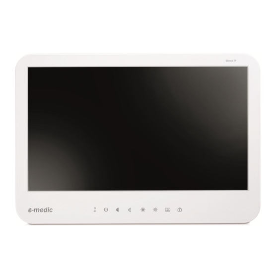
B. The Packing / Outline / I/O / Control Buttons Basic packing list -- . The medical PC: e-medic Silence TP 2 (fanless) or TP 1 (smart fan) . Power adaptor (Sinpro MPU101-105) . AC power cord . Touch stylus pen . - Page 15 . e-medic Silence TP 2 . The I/O interface (basic configuration)
- Page 16 . The control buttons & LED indicators Control buttons & LED indicators 1. HDD indicator: Dark - non-operating/stand-by Amber blinking - accessing 2. Battery indicator: Dark - non-operating Amber - operating Amber blinking - battery low 3. Power indicator: Dark - off Green - on 4.
-
Page 17: Others
C. Others . To clean or disinfect the system To clean or disinfect the system, to avoid any damage to the touch panel and the plastic housing, please check below chemical resistance table to ensure you disinfectant does not contain harmful ingredients. We suggest to use Ethanol and do check with the personal who is responsible for disinfecting. - Page 18 Chemical Plastic housing 40% Sodium Hydroxid Damage Acetone Damage Carbitol Acetate Damage Cellosolve Acetate Damage Ethanol / Alcohol 500g load with 95% Alcohol--> OK Methylene Chloride Damage Hydrochloric Acid - 6% Damage Hexane Damage Isopropanol (Isopropyl Alcohol)/Propanol Damage Methyl Ethyl Ketone Damage Heptane Damage...
- Page 19 . The internal battery (optional) For those systems installed with internal battery, below is the specification. Battery cell type Lithium-Ion rechargeable battery cell (2000mAh/cell) Configuration 2S2P Typical capacity 4000mAh (for two cells) Minimum capacity 3800mAh (for two cells) Nominal voltage 7.3 V (average) Energy 29.2 Wh (typical) / 27.74 Wh (minimum)
-
Page 20: Bios
III. BIOS Immediately after powering on the system, during the POST (Power On Self Test) stage, press the <Del> key to enter the BIOS setup utility program. Follow the menu & the keys instruction to modify the BIOS configuration & settings. - Page 21 Advanced -- Launch OpROM Support Launch PXE OpROM Enables or disables Boot Option for Legacy Network Devices. Launch Storage OpROM Enables or disables Boot Option for Legacy Mass Storage Devices with Option ROM PCI Subsystem Settings PCI ROM Priority In Case of multiple Option ROMs (Legacy and EFI Compatible), specifies what PCI Option ROM to launch.
- Page 22 Extended Tag If ENABLED allows Device to use 8-bit Tag field as a requester. No Snoop Enables or Disables PCI Express Device No Snoop option. Maximum Payload Set Maximum Payload of PCI Express Device or allow System BIOS to select the value Maximum Read Request Set Maximum Read Request Size of PCI Express Device or allow System...
- Page 23 Core-Multi Processing Enable or Disable Core-Multi Processing mode. Execute Disable Bit XD can prevent certain classes of malicious buffer overflow attacks when combined with a supporting OS (Windows Server 2003 SP1, Windows XP SP2, SuSE Linux 9.2, RedHat Enterprise 3 Update 3.) Limit CPUID Maximum Disabled for Windows XP.
- Page 24 TV1 Standard TV2 Standard Active LFP Select the Active LFP Configuration. No LVDS:VBIOS does not enable LVDS. INT-LVDS:VBIOS enables LVDS driver by Integrated encoder. SDV0 LVDS:VBIOS enables LVDS driver by SDV0. USB Configuration Legacy USB Support Allows USB devices to be used in MS-DOS. EHCI Hand-off This is a workaround for 0Ses without EHCI hand-off support.
- Page 25 Serial Port 3 Configuration Set Parameters of Serial Port 3 (COM E). Serial Port 4 Configuration Set Parameters of Serial Port 4 (COM F). Serial Port Console Redirection Serial Port Console Redirection.
- Page 26 Chipset -- Host Bridge/South Bridge This screen provides information on Host Bridge/South Bridge parameters.
- Page 27 Boot -- Setup Prompt Timeout Number of seconds to wait for setup activation key. 65535(0xFFFF) means indefinite waiting. Bootup Numlock State Selects the keyboard NumLock state. Quiet Boot Allows you to determine whether to display the AMI Logo at system startup. Disabled displays normal POST message.
- Page 28 Always Do not allow disabling GA20. Option ROM Messages Sets display made for option ROM. Interrupt 19 Capture Enables or disables Option ROMs to Trap Int 19. Boot Option Priorities Specifies the sequence of loading the operating system from the installed hard drives.
- Page 29 Security – Enables or disables the security chip. It is recommended that you use this function with the Administrator/User password.
- Page 30 Save & Exit – Save Changes and Exit Exit system setup after saving the changes. Discard Changes and Exit Exit system setup without saving any changes. Save Changes and Reset Reset the system after saving the changes. Discard Changes and Reset Reset system setup without saving the changes.
- Page 31 Baaske Medical GmbH & Co. KG Bacmeisterstr. 3 32312 Lübbecke Tel: +49 5741 236027 – 0 Fax: +49 5741 236027 – 99 vertrieb@baaske.net www.baaske-medical.de...
Need help?
Do you have a question about the Silence TP 2 and is the answer not in the manual?
Questions and answers