Table of Contents
Advertisement
Advertisement
Table of Contents
Troubleshooting

Related Manuals for PolyScience LS Series


Summary of Contents for PolyScience LS Series
- Page 1 Operator’s Manual LS-Series Compact Chiller 110-445 12.20.12...
-
Page 2: Table Of Contents
Model LS52 50Hz Compact Chiller Specifications ..........................16 General Information & Specifications ..............................17 RS232 Serial Communications (Optional) ............................18 Equipment Disposal (WEEE Directive) ........................ 19 Service and Technical Support ..........................19 Replacement Parts and Accessories ......................... 20 PolyScience Chiller Fluids ............................ 21 Warranty................................. 21 110-445... -
Page 3: Introduction
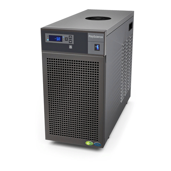
Introduction The LS-Series Compact Chiller provides cooling power for demanding applications and serves as an economical alternative to tap water cooling systems. It features a microprocessor-based controller, digital temperature display (°C or °F), and simple operation and maintenance. To optimize cooling efficiency and performance, this sophisticated Chiller also features a modulated refrigeration system. -
Page 4: Safety Recommendations
Safety Recommendations To prevent injury to personnel and/or damage to property, always follow your workplace’s safety procedures when operating this equipment. You should also comply with the following safety recommendations: • Always connect the power cord on this unit to a grounded (3-prong) power outlet. Make certain that the outlet is the same voltage and frequency as your unit. -
Page 5: Controls And Components
Controls and Components Reservoir Cap Circuit Breaker / Up & Down Arrow Buttons Power Switch Temperature IEC Power Units LEDs Connection Fluid Level Heating & Indicator Cooling LEDs RS-232 Connection On/Off Button Temperature (optional; not Display shown) Identification Label Set Button Air Filter Fluid Outlet Compartment... -
Page 6: Installation And Startup
Installation and Startup WARNING: Be sure all power is off before proceeding. Site Requirements Ambient Temperature and Relative Humidity The Chiller is designed for indoor installation in ambient temperatures between 5° and 35°C (41° and 95°F); relative humidity should not exceed 80% (non-condensing). Location The Chiller should be installed on a strong, level surface. -
Page 7: Plumbing
Plumbing Process Piping The Chiller has two internally threaded (0.5 inch ID NPT) fittings on the rear of the instrument housing for the process fluid connections. Two sets of 90° barbed hose adapters (0.5 inch and 5/8 inch) are supplied with the unit for connecting these fittings to the process piping. -
Page 8: Startup
Startup Process Coolant Suitable Fluids WARNING: Only use fluids that will satisfy safety, health, and equipment compatibility requirements. Caustic, corrosive, or flammable fluids must never be used. The Chiller is designed to accommodate a variety of coolant fluids (water, glycol mixtures, etc). For most applications above 20°C (68°F), distilled water is satisfactory. -
Page 9: Electrical Power
Electrical Power Plug the Chiller’s power cord into an appropriate electrical outlet. Place the Circuit Breaker/Power Switch on the rear of the in strument enclosure in the “On” position. Three decimal points will appear on the Temperature display. Starting Process Fluid Flow ss he Power Button on the front panel. -
Page 10: Displaying And Adjusting The Set Point
Displaying and Adjusting the Set Point Press the Set button on the front panel. The current set point temperature will be displayed and the decimal point at the bottom right of the display will flash, indicating the temperature can be changed. Press the Up and Down arrow button to adjust the set point temperature. -
Page 11: Low Temperature Limit (L-##)
Low Temperature Limit (L-##) This menu item serves as a user adjustable low temperature limit. It limits how low the temperature set point may be set as well as lowest process fluid temperature at which the Chiller will operate. When this value is exceeded, the appropriate alarm or fault message will appear on the display (see Display, Fault and Error Messages... -
Page 12: Temperature Calibration (C #.#)
Temperature Calibration (C #.#) The Chiller’s temperature probe is accurate to ±0.25°C. Therefore, if the displayed temperature 15°C, the actual temperature will be between 14.75°C and 15.25°C. This menu item allows you to adjust the Chiller’s temperature reading to match that of a traceable standard or another piece of equipment. -
Page 13: Display, Error And Fault Messages
Display, Error and Fault Messages When certain conditions are detected, message codes flash on the display. Depending on the nature of the condition, power to various systems components is removed. When the condition is rectified, press the front panel Power button or turn power switch/circuit breaker Off then On to clear the fault or error. Message Code Description Action Required... -
Page 14: Routine Maintenance And Troubleshooting
Routine Maintenance and Troubleshooting The Chiller is designed to require a minimum of periodic maintenance. Magnetic Drive Centrifugal Pump When used under continuous operating conditions, this pump should be oiled every six (6) months with SAE 20 oil. The pump incorporates two oil ports for this purpose. To access the pump: Turn both power switches off and unplug the power cord. -
Page 15: Cleaning Exterior Surfaces
Cleaning Exterior Surfaces Only mild detergents and water or an approved cleaner should be used on the painted surfaces of the Chiller. Do not allow cleaning liquids or sprays to come in direct contact with the digital display. Troubleshooting NOTE: Many problems can be resolved by restoring the factory defaults. If this solves the problem, be careful when restoring your operational settings in order not to repeat the problem. -
Page 16: Technical Information
Technical Information Model LS51/LS53 60Hz Compact Chiller Specifications Performance 120/230V, 60Hz Working temperature range -20° to +40°C / -4° to +104°F Operating temperature range -20° to +60°C / -4° to +140°F Temperature Stability ±0.1°C (±0.18°F) Cooling capacity Ethylene Glycol & Water (50/50 mix) Pump MX Centrifugal M1 Centrifugal... -
Page 17: Model Ls52 50Hz Compact Chiller Specifications
Model LS52 50Hz Compact Chiller Specifications Performance 240V, 50Hz Working temperature range -20° to +40°C / -4° to +104°F Operating temperature range -20° to +60°C / -4° to +140°F Temperature Stability ±0.1°C (±0.18°F) Cooling capacity: Ethylene Glycol & Water (50/50 mix) Pump M2 Centrifugal MY Centrifugal... -
Page 18: General Information & Specifications
General Information & Specifications Safety Auto-restart on power failure Low flow alarm and power cutoff High temperature safety High temperature limit Yes (user adjustable) Low temperature limit Yes (user adjustable) Compliance CSA-US WEEE Compliant RoHS Compliant Construction Outer case Epoxy powder coated steel Brass, Copper, Stainless Steel, EPDM Rubber, Alcryn, Wetted parts Nylon, PVC, and Polyethylene... -
Page 19: Rs232 Serial Communications (Optional)
RS232 Serial Communications (Optional) This option allows you to remotely control the Chiller and/or output temperature readings to an external recorder or other auxiliary device. The maximum communications distance for Chillers equipped with the RS232 option is 15 meters (50 feet). Serial Connector —... -
Page 20: Equipment Disposal (Weee Directive)
Equipment Disposal (WEEE Directive) This equipment is marked with the crossed out wheeled bin symbol to indicate it is covered by the Waste Electrical and Electronic Equipment (WEEE) Directive and is not to be disposed of as unsorted municipal waste. Any products marked with this symbol must be collected separately, according to the regulatory guidelines in your area. -
Page 21: Replacement Parts And Accessories
Replacement Parts and Accessories Description Part Number Reservoir Cap 300-460 Reservoir Spill Cup 300-575 Centrifugal Pump, M1 (120 V, 60 Hz) 525-782 Centrifugal Pump, M2 (230/240 V, 50/60 Hz) 525-783 Centrifugal Pump, MX (120 V, 60 Hz) 525-784 Centrifugal Pump, MY (230/240 V, 50/60 Hz) 525-785 Turbine Pump, TX (120 V, 60 Hz) 525-780... -
Page 22: Polyscience Chiller Fluids
PolyScience Chiller Fluids Circulating Bath Fluids Quantity Part Number polyclean Algaecide 8 oz / 236 ml 004-300040 polyclean Algaecide Twelve 8 oz / 236 ml bottles 004-300041 polycool EG -25 (ethylene glycol) 1 gal / 4.5 liter 060340 1 gal / 4.5 liter...
Need help?
Do you have a question about the LS Series and is the answer not in the manual?
Questions and answers