Table of Contents
Advertisement
Quick Links
Advertisement
Table of Contents
Troubleshooting

Subscribe to Our Youtube Channel
Related Manuals for PolyScience LS Series


Summary of Contents for PolyScience LS Series
- Page 1 Operator’s Manual LS-Series Compact Chiller 110-445 09.01.11...
-
Page 2: Table Of Contents
................................................................................20 ....PolyScience Chiller Fluids PolyScience Chiller Fluids ........ PolyScience Chiller Fluids PolyScience Chiller Fluids ........................................................................................... . 21 21 21 21 ........ -
Page 3: Introduction
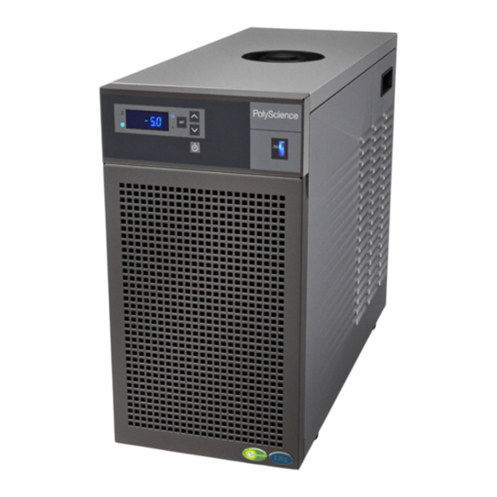
Introduction Introduction Introduction Introduction The LS-Series Compact Chiller provides cooling power for demanding applications and serves as an economical alternative to tap water cooling systems. It features a microprocessor-based controller, digital temperature display (°C or °F), and simple operation and maintenance. To optimize cooling efficiency and performance, this sophisticated Chiller also features a modulated refrigeration system. -
Page 4: Safety Recommendations
Safety Recommendations Safety Recommendations Safety Recommendations Safety Recommendations To prevent injury to personnel and/or damage to property, always follow your workplace’s safety procedures when operating this equipment. You should also comply with the following safety recommendations: • Always connect the power cord on this unit to a grounded (3-prong) power outlet. Make certain that the outlet is the same voltage and frequency as your unit. -
Page 5: Contr Controls And Components Contr Ols And Components Ols And Components
Controls and Components Controls and Components Controls and Components Controls and Components Reservoir Cap Circuit Breaker / Up & Down Arrow Buttons Power Switch Temperature IEC Power Units LEDs Connection Fluid Level Heating & Indicator Cooling LEDs RS-232 Connection On/Off Button Temperature (optional;... -
Page 6: Installation And Startup
Installation and Startup Installation and Startup Installation and Startup Installation and Startup WARNING: WARNING: Be sure all power is off before proceeding. WARNING: WARNING: Site Requirements Site Requirements Site Requirements Site Requirements Ambient Temperature and Relative Humidity Ambient Temperature and Relative Humidity Ambient Temperature and Relative Humidity Ambient Temperature and Relative Humidity The Chiller is designed for indoor installation in ambient temperatures between 5°... -
Page 7: Fluid Filter
Chiller are compatible with the fluid, temperature, and pressure being used. Pressure Ratings — Hoses should be able to withstand the largest pressure that they will encounter. • Flexible Tubing — Avoid tubing that will expand and take up fluid volume when operating at the desired •... -
Page 8: Startup
Startup Startup Startup Startup Process Coolant Process Coolant Process Coolant Process Coolant Suitable Fluids WARNING: WARNING: Only use fluids that will satisfy safety, health, and equipment compatibility requirements. WARNING: WARNING: Caustic, corrosive, or flammable fluids must never be used. The Chiller is designed to accommodate a variety of coolant fluid9D#)(°9EtP1981hrenfn(°9(h(9j°h#(N9E P#D8h8h #.9981hND1ll9jr 110-445... -
Page 9: Electrical Power
Electrical Power Electrical Power Electrical Power Electrical Power Plug the Chiller’s power cord into an appropriate electrical outlet. Place the Circuit Breaker/Power Switch on the rear of the instrument enclosure in the “On” position. Three decimal points will appear on the Temperature display. Starting Process Fluid Flow Starting Process Fluid Flow Starting Process Fluid Flow... -
Page 10: Displaying And Adjusting The Set Point
Displaying and Adjusting the Set Point Displaying and Adjusting the Set Point Displaying and Adjusting the Set Point Displaying and Adjusting the Set Point Press the Set button on the front panel. The current set point temperature will be displayed and the decimal point at the bottom right of the display will flash, indicating the temperature can be changed. -
Page 11: Low Temperature Limit (L-##)
Low Temperature Limit (L- - - - ## Low Temperature Limit (L ##) ) ) ) Low Temperature Limit (L Low Temperature Limit (L This menu item serves as a user adjustable low temperature limit. It limits how low the temperature set point may be set as well as lowest process fluid temperature at which the Chiller will operate. -
Page 12: Temperature Calibration (C #.#)
Temperature Calibration (C Temperature Calibration (C # # # # ..# # # # ) ) ) ) Temperature Temperature Calibration (C Calibration (C The Chiller’s temperature probe is accurate to ±0.25°C. Therefore, if the displayed temperature 15°C, the actual temperature will be between 14.75°C and 15.25°C. -
Page 14: Routine Maintenance And Troubleshooting
Routine Maintenance and Troubleshooting Routine Maintenance and Troubleshooting Routine Maintenance and Troubleshooting Routine Maintenance and Troubleshooting The Chiller is designed to require a minimum of periodic maintenance. Magnetic Drive Centrifugal Pump Magnetic Drive Centrifugal Pump Magnetic Drive Centrifugal Pump Magnetic Drive Centrifugal Pump When used under continuous operating conditions, this pump should be oiled every six (6) months with SAE 20 oil. -
Page 15: Cleaning Exterior Surfaces Cleaning Exterior Surfaces
Cleaning Exterior Surfaces Cleaning Exterior Surfaces Cleaning Exterior Surfaces Cleaning Exterior Surfaces Only mild detergents and water or an approved cleaner should be used on the painted surfaces of the Chiller. Do not allow cleaning liquids or sprays to come in direct contact with the digital display. Troubleshooting Troubleshooting Troubleshooting... -
Page 16: Technical Information
Technical Information Model LS51/LS53 60Hz Compact Chiller Specifications Model LS51/LS53 60Hz Compact Chiller Specifications Model LS51/LS53 60Hz Compact Chiller Specifications Model LS51/LS53 60Hz Compact Chiller Specifications Performance 120/230V, 60Hz Performance 120/230V, 60Hz Performance 120/230V, 60Hz Performance 120/230V, 60Hz Working temperature range -20°... -
Page 17: Model Ls52 50Hz Compact Chiller Specifications
Model LS52 50Hz Compact Chiller Specifications Model LS52 50Hz Compact Chiller Specifications Model LS52 50Hz Compact Model LS52 50Hz Compact Chiller Specifications Chiller Specifications Performance 240V, 50Hz Performance 240V, 50Hz Performance 240V, 50Hz Performance 240V, 50Hz Working temperature range -20° to +40°C / -4° to +104°F Operating temperature range -20°... -
Page 18: General Information & Specifications
General Information & Specifications General Information & Specifications General Information & Specifications General Information & Specifications Safety Safety Safety Safety Auto-restart on power failure Low flow alarm and power cutoff High temperature safety High temperature limit Yes (user adjustable) Low temperature limit Yes (user adjustable) Compliance Compliance... -
Page 19: Rs232 Serial Communications (Optional)
RS232 Serial Communications RS232 Serial Communications (Optional) (Optional) RS232 RS232 Serial Communications Serial Communications (Optional) (Optional) This option allows you to remotely control the Chiller and/or output temperature readings to an external recorder or other auxiliary device. The maximum communications distance for Chillers equipped with the RS232 option is 15 meters (50 feet). -
Page 20: Equipment Disposal (Weee Directive)
Equipment Disposal (WEEE Directive) Equipment Disposal (WEEE Directive) Equipment Disposal (WEEE Directive) Equipment Disposal (WEEE Directive) This equipment is marked with the crossed out wheeled bin symbol to indicate it is covered by the Waste Electrical and Electronic Equipment (WEEE) Directive and is not to be disposed of as unsorted municipal waste. -
Page 21: Replacement Parts And Accessories
Replacement Parts and Accessories Replacement Parts and Accessories Replacement Parts and Accessories Replacement Parts and Accessories Description Description Description Description Part Number Part Number Part Number Part Number Reservoir Cap 300-460 Reservoir Spill Cup 300-575 Centrifugal Pump, M1 (120 V, 60 Hz) 525-782 Centrifugal Pump, M2 (230/240 V, 50/60 Hz) 525-783... -
Page 22: Polyscience Chiller Fluids
PolyScience Chiller Fluids PolyScience Chiller Fluids PolyScience Chiller Fluids PolyScience Chiller Fluids Circulating Bath Fluids Circulating Bath Fluids Circulating Bath Fluids Circulating Bath Fluids Quantity Quantity Quantity Quantity Part Number Part Number Part Number Part Number polyclean Algaecide 8 oz / 236 ml...
Need help?
Do you have a question about the LS Series and is the answer not in the manual?
Questions and answers