
Related Manuals for PolyScience DA500


Summary of Contents for PolyScience DA500
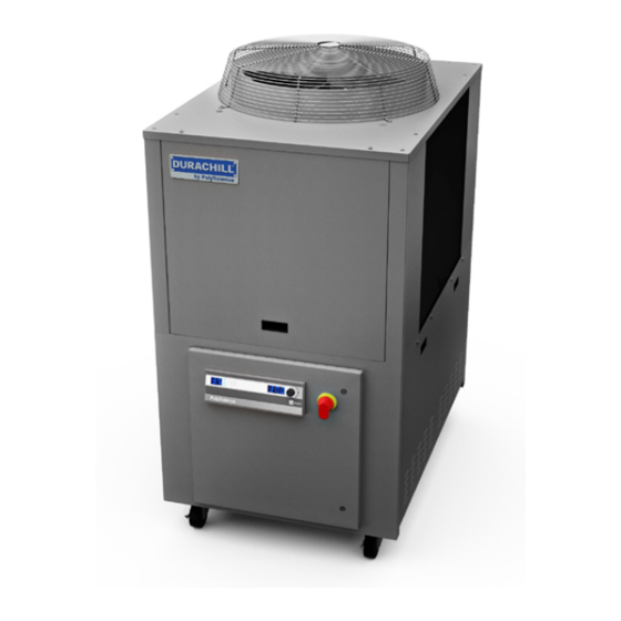
- Page 1 Operator’s Manual ™ DuraChill Air- and Water-Cooled Chillers 5, 7.5 and 10 HP 110-279 26 June 2013...
-
Page 2: Table Of Contents
Table of Contents Introduction................................4 Standard and Optional Features ......................... 4 Standard Features ............................4 Optional Features............................. 4 General Safety Information..........................5 Safety Recommendations............................ 6 Regulatory Compliance and Testing ........................7 Unpacking................................7 Controls and Components ........................... 8 Control System ..............................8 Control Panel .............................. - Page 3 Alarm Output ..............................15 RS-232/RS-485 Serial Output........................15 External Piping..............................16 General Considerations ..........................16 Process Fluid Connections ..........................16 Facility Water Connections ..........................16 Reservoir Drain .............................. 16 Reservoir Vent ............................... 16 Full Flow Bypass ............................17 Process Coolant ..............................18 Suitable Fluids..............................
- Page 4 Chiller Specifications ............................38 Air-Cooled Chillers (DA500, DA750, DA1000) ....................38 Water-Cooled Chillers (DW500) ........................38 Electrical Specifications ............................. 39 DA500 Chillers ............................... 39 DW500 Chillers .............................. 40 DA750 Chillers ............................... 41 DA1000 Chillers ............................. 41 Pump Performance............................42 RS-232 Serial Communications (RS-485 Option) ..................... 43 Equipment Disposal (WEEE Directive) ......................
-
Page 5: Introduction
Introduction The PolyScience line of DuraChill Chillers provide cooling power for demanding applications and serve as an economical alternative to tap water cooling systems. All models feature a microprocessor-based controller, digital Temperature Display (°C or °F), one-touch set point display, and digital Pressure/Flow Rate Display (PSI, kPa, GPM, LPM) with push-button selection. -
Page 6: General Safety Information
General Safety Information When installed, operated, and maintained according to the directions in this manual and common safety procedures, your DuraChill Chiller should provide safe and reliable temperature control. Please ensure that all individuals involved in the installation, operation, or maintenance of this Chiller read this manual thoroughly prior to working with the unit. -
Page 7: Safety Recommendations
Safety Recommendations It is the user’s responsibility to read and understand all instructions and safety precautions included in this manual prior to installing or operating this equipment. Contact our Customer Service Department with any questions regarding the operation of this Chiller or the information contained in this manual. WARNING: All warning labels should be carefully observed. -
Page 8: Regulatory Compliance And Testing
Regulatory Compliance and Testing CSA UL (5 HP 60Hz units) CAN/CSA C22.2 No. 61010-1-04 — Safety Requirements for Electrical Equipment for Measurement, Control and Laboratory Use, Part I: General Requirements. CAN/CSA C22.2 No. 61010-010-04 — Safety Requirements for Electrical Equipment for Measurement, Control and Laboratory Use - Part 2-010: Particular Requirements for Laboratory Equipment for the Heating of Materials. -
Page 9: Controls And Components
Controls and Components Your DuraChill Chiller consists of three basic sub-systems: Control • Fluid circulation • Cooling • This section describes these sub-systems in detail and includes information on the available options. Please note that your Chiller may or may not be equipped with all the components discussed. Control System Control Panel —... -
Page 10: Fan Cycling Switch
Fan Cycling Switch — This switch control fan operation. The fan turns ON when the discharge pressure of the refrigerant exceeds 400 psi (27.8 bar) and remains running until the pressure falls below 300 psi (20.7 bar). NOTE: 10 HP Chillers have two fans. One fan turns ON with the compressor and runs continuously as long as the compressor is ON;... -
Page 11: Refrigerant Safety Relief Valve
Hot Gas Bypass Solenoid Valve — Injects refrigerant vapor into the Evaporator to help maintain a constant temperature when the temperature of the process fluid falls below the temperature set point. Under low- and no- load conditions, temperature continues to fall until it reaches the “Lb” lower band and shuts the Compressor OFF. -
Page 12: Component Identification
Component Identification Front – All Models Power Switch / Disconnect Control Panel 5 HP and 7.5 HP Chillers – Rear 110-279... -
Page 13: Hp Chillers - Rear
10 HP Chillers – Rear 110-279... -
Page 14: Installation And Startup
The front and rear vents of the Chiller must be a minimum of 24 inches (61 cm) away from walls or vertical surfaces so air flow is not restricted. Overall Dimensions Model Length Width Height DA500 56 in. (142.2 cm) 34.5 in. (88 cm) 67 in. (170.2 cm) DW500 56 in. (142.2 cm) 34.5 in. (88 cm) 32.1 in. -
Page 15: Electrical Power
Electrical Power WARNING: Make sure the main power switch is in the OFF position before connecting or disconnecting electrical power from the unit. Follow all applicable electrical and safety codes and procedures when connecting power to the unit. Electrical connections should be made by an authorized electrical installer. WARNING: Make certain that the electrical supply is the same voltage and frequency as your unit (see identification label). -
Page 16: Alarm Output
Signal Inputs/Outputs Remote On / Off and Alarm Output Remote On / Off This allows the operator to turn the Chiller ON and OFF using a remote dry contact. The Chiller is ON when the contact is open; it is OFF when the contact is closed. A 10-ft (3 m) cord with 5-pin mating plug is provided. Alarm Output This allows the operator to connect a remote alarm device to the Chiller. -
Page 17: External Piping
External Piping WARNING: All facility water connections must be made by a licensed plumber. General Considerations To maintain a safe workplace and avoid leaks, special care should be taken when choosing hoses and connectors for the Chiller. It is the user’s responsibility to ensure that the tubing and fittings connected to the Chiller are compatible with the fluid, temperature, and pressure being used. -
Page 18: Full Flow Bypass
If the Chiller is equipped with the heater option, a Reservoir vent should be installed. This vent relieves pressure within the Reservoir as coolant heats and expands. It may be also necessary to vent and/or add a venting pipe to the Chiller to prevent siphoning and/or overflow due to the amount of fluid external to the Chiller’s reservoir and/or location of the process being cooled. -
Page 19: Process Coolant
Higher temperatures and higher concentrations of additives can hasten deposit build up. An algaecide may be added to the coolant fluid to prevent algae growth (see PolyScience Chiller Fluids). 110-279... -
Page 20: Startup
Startup CAUTION: The first time the Chiller is operated it should run for 12 hours in the Standby mode to allow the compressor crankcase heater to boil off any refrigerant absorbed in the compressor oil. CAUTION: DO NOT turn Controller power ON until the Reservoir has been filled. When Controller power is turned ON, the pump automatically begins pumping. -
Page 21: Starting Process Fluid Flow
Starting Process Fluid Flow 1. Place the Power Switch / Disconnect in the ON position. The Control Panel displays will respond by showing five decimal points (..). This indicates that the Chiller is in the Standby mode and is ready for power up. -
Page 22: Normal Operation
Normal Operation Pressure / Flow Rate Unit Temperature Unit Pressure / Flow Rate Display Select / Set Knob Units / Menu Temperature Power Button Select Button Display P ower On When the Power Switch / Disconnect is placed in the ON position, the Controller goes into a “Standby” mode. Five decimal points (…..) will appear on the Controller’s displays. -
Page 23: Adjusting The Set Point Temperature
A djusting the Set Point Temperature Press the Select/Set Knob on the front panel. The current set point temperature will be displayed and the decimal point at the bottom right of the display will flash, indicating the temperature can be changed. Rotate the Select/Set Knob until the desired set point temperature is displayed. - Page 24 Menu Item Description Choices / Ranges Default Setting High Temperature Limit — Limits the maximum allowable 5° to 131°F 95°F (35°C) set point temperature. Audio and visual alarm indicators are (-15° to +55°C) activated when the measured fluid temperature reaches the HL temperature setting.
- Page 25 Menu Item Description Choices / Ranges Default Setting Upper Band — This sets how many degrees the process 1.0° to 5.0°C 2.0°C temperature can rise above set point before the compressor Always displayed will turn ON. It is displayed and settable in °C only. and set in °C Calibration Offset —...
-
Page 26: High Temperature Limit (Hl)
Menu Item Description Choices / Ranges Default Setting Password — For factory use only. 0 to 999 HGB Valve Delay — For factory use only. 0 to 999 Fuse Bits — The current Fuse Bits (Fb) setting appears after the td setting and can be viewed, but not changed. -
Page 27: High Ambient Temperature Limit (Ha)
High Ambient Temperature Limit (HA) NOTE: This value is always set in °C. This menu item protects the Chiller from overheating due to a high ambient temperature. Should the ambient temperature rise above the limit value, the audio and visual alarms will activate and the compressor, heater, fan, and pump will turn OFF. -
Page 28: Lower Band (Lb)
● Lower Band (Lb) NOTE: This value is always displayed/set in °C. This menu item allows you to set how many degrees the process temperature can fall below set point before the Compressor will turn OFF. To change the lower band value, rotate the Select/Set Knob until the desired value is displayed. Upper Band (Ub) NOTE: This value is always displayed/set in °C. -
Page 29: Compressor Delay (Cd)
Compressor Delay (Cd) This menu item allows you to adjust the minimum amount of time (in seconds) the Compressor should be OFF before it cycles back ON. To change the compressor delay, rotate the Select/Set Knob until the desired value is displayed. Flow Rate Calibration (Fc) NOTE: Your Chiller’s flow rate is calibrated at the factory at the nominal flow value for the installed pump. -
Page 30: Communications Baud Rate (Pc)
Baud Rate (PC) Communications This menu item allows you to establish the baud rate for serial communication. Allowable settings are 0 (no serial communication), 24 (2400 baud), 48 (4800 baud), 96 (9600 baud), 192 (19200 baud). To change the displayed setting, rotate the Select/Set Knob until the desired baud rate is displayed. Press the Select/Set Knob or allow the display to time out to accept the displayed value. -
Page 31: Enabling / Disabling The Local Lockout
Enabling / Disabling the Local Lockout This feature is used to prevent unauthorized or accidental changes to set point and other operational values. When enabled, the values for set point and operational parameters can be displayed, but not changed: To enable the local lockout, press and hold the Select/Set Knob until LLO is displayed (approximately 5 seconds). -
Page 32: Display, Alarm And Error Messages
Display, Alarm and Error Messages When an alarm or error condition is detected, Ft appears on the Pressure/Flow Rate Display and a corresponding code flashes on the Temperature Display. Operational limit parameter alarms will shut down the compressor, fan, pump, and heaters. Alphabetical codes will also appear on the Temperature Display. An audio alarm will also sound. - Page 33 Code Description Action Required Default Fault – RTD sensor failure. Internal RTD probe fault Check for open or shorted sensor (reference resistance value: 100 ohms @ 0°C / 138.5 ohms @ External RTD probe fault 100°C. If probe tests good, replace Control PCB. Fault –...
-
Page 34: Automatic Restart From Alarm Mode
Code Description Action Required Default Alarm – The temperature set point is lower than the low limit temperature setting. The display alternates between ELL and the fluid temperature. The unit Low limit temperature alarm 39°F (4°C) continues normal operation. If the fluid temperature drops below the LL setting, Fault 02 is activated. -
Page 35: Routine Maintenance
Routine Maintenance Recommended Routine Maintenance Schedule Routine Maintenance Procedure Frequency Check reservoir coolant level Monthly Check coolant freeze protection Monthly Inspect and clean inline strainer Weekly for first month of operation; every 3 months thereafter. Inspect and clean air filters Weekly for first month of operation;... -
Page 36: Air Filters
Air Filters Chillers incorporate two or more high-efficiency, removable air filters. These should be inspected weekly during the first month of operation to determine how frequently cleaning is required. Units located in dusty or oily environments will require more frequent air filter cleaning. CAUTION: DO NOT allow the air filters to become caked with dust or coated with an oily film. -
Page 37: Troubleshooting
Troubleshooting NOTE: Many problems can be resolved by restoring the factory defaults. If this solves the problem, be careful when restoring your operational settings in order not to repeat the problem. To restore the factory default settings: 1. Place the Power Switch / Disconnect in the OFF position. Press and hold the Units/Menu Button (for °F) or the Power Button (for °C) while returning the Power Switch / Disconnect to the ON position. -
Page 38: Compressor Overload Fault (Ft20)
Compressor Overload Fault (Ft 20) The Chiller has both low and high refrigerant pressure sensors. They are wired in series and connect to DAF2 on the Control PCB. If either sensor opens, the Ft 20 alarm is activated. To troubleshoot, measure the continuity across each senor. -
Page 39: Technical Information
Technical Information Chiller Specifications Air-Cooled Chillers (DA500, DA750, DA1000) Model DA500 DA750 DA1000 Process temperature range 32° to 86°F (0° to 30°C) Temperature stability ±2.0°F (±1.11°C) Ambient operating temperature 60° to 104°F (16° to 40°C) Copeland Scroll compressor 5 HP 7.5 HP... -
Page 40: Electrical Specifications
Electrical Specifications DA500 Chillers Max. Operating Max. Operating Max. Operating Max. Operating Current / Fuse – Current / Fuse – Current / Fuse – Current / Fuse – Circuit Breaker Size Circuit Breaker Size Circuit Breaker Size Circuit Breaker Size... -
Page 41: Dw500 Chillers
DW500 Chillers Max. Operating Max. Operating Max. Operating Max. Operating Current / Fuse – Current / Fuse – Current / Fuse – Current / Fuse – Circuit Breaker Size Circuit Breaker Size Circuit Breaker Size Circuit Breaker Size Voltage / Phase / with 3000 Watt Heater with 7500 Watt Heater with 9000 Watt Heater... -
Page 42: Da750 Chillers
DA750 Chillers Max. Operating Max. Operating Max. Operating Current / Fuse – Current / Fuse – Current / Fuse – Circuit Breaker Size Circuit Breaker Size Circuit Breaker Size Voltage / Phase / with 3000 Watt Heater with 9000 Watt Heater Model with no heaters Hertz... -
Page 43: Pump Performance
Pump Performance Stainless Steel 240/460V Bronze 240/460V Nom. Nom. Centrifugal 3 phase Turbine 3 phase 1 HP centrifugal 215-733 1.5 HP turbine 215-483 2 HP centrifugal 215-678 2 HP turbine 215-354 3 HP centrifugal 215-738 3 HP turbine 215-484 5 HP centrifugal 215-780 5 HP turbine 215-485... -
Page 44: Rs-232 Serial Communications (Rs-485 Option)
RS-232 Serial Communications (RS-485 Option) Serial Connector — A 9-pin D-connector (optional) is provided on the back panel of the Chiller for RS-232 / RS- 485 data communication. A serial cable that uses only the following pins should be used to connect the Chiller to the computer: RS-232 RS-485... -
Page 45: Equipment Disposal (Weee Directive)
Equipment Disposal (WEEE Directive) This equipment is marked with the crossed out wheeled bin symbol to indicate it is covered by the Waste Electrical and Electronic Equipment (WEEE) Directive and is not to be disposed of as unsorted municipal waste. Any products marked with this symbol must be collected separately, according to the regulatory guidelines in your area. -
Page 46: Polyscience Chiller Fluids
PolyScience Chiller Fluids Circulating Bath Fluids Quantity Part Number polyclean Algaecide 8 oz / 236 ml 004-300040 polyclean Algaecide Twelve 8 oz / 236 ml bottles 004-300041 polycool EG -25 (ethylene glycol) 1 gal / 4.5 liter 060340 polycool PG -20 (propylene glycol) 1 gal / 4.5 liter... -
Page 47: Appendix
Appendix Flow Schematic – Air-Cooled Chillers FLOW DIAGRAM AIR-COOLED PRESSURE SWITCH REFRIGERANT 15 PSI CO CYCLING HIGH PRESSURE 30 PSI CI SWITCH PRESSURE RELIEF VALVE TB1-1,3 SWITCH (675 PSI) (630 PSI) "Y" (WITH RESET STRAINER FROM BUTTON) PROCESS HOT GAS SUCTION BYPASS LINE... -
Page 48: Flow Schematic - Water-Cooled Chillers
Flow Schematic – Water-Cooler Chillers FLOW DIAGRAM WATER-COOLED PRESSURE SWITCH REFRIGERANT 15 PSI CO HIGH PRESSURE 30 PSI CI PRESSURE RELIEF VALVE SWITCH (675 PSI) (630 PSI) "Y" STRAINER (WITH RESET BUTTON) FROM PROCESS HOT GAS SUCTION BYPASS LINE COMPRESSOR FILTER SIGHT DRIER... -
Page 49: Wiring Diagram - 5 Hp And 7.5 Hp Air-Cooled Chillers
Wiring Diagram – 5 HP and 7.5 HP Air-Cooled Chillers L1 L2 L3 GROUND TB 3 JUNCTION BOX (REAR OF UNIT) MULTI -TAP TRANSFORMER FUSE FRONT PANEL 120VAC OUTPUT BLOCK DISCONNECT SWITCH TB 2 DISTRIBUTION 3.5A REMOTE CUTOFF SWITCH BLOCK 1.4A 1.4A FLOW... -
Page 50: Wiring Diagram - 10 Hp Air-Cooled Chillers
Wiring Diagram – 10 HP Air-Cooled Chillers L1 L2 L3 GND GROUND JUNCTION BOX TB 3 (REAR OF UNIT) MULTI -TAP TRANSFORMER FUSE FRONT PANEL 120VAC OUTPUT TB 2 BLOCK DISCONNECT REMOTE CUTOFF SWITCH SWITCH 3.5A 1.4A FLOW METER 1.4A FLOW METER DISTRIBUTION SUPPLY VOLTAGE... -
Page 51: Wiring Diagram - 5 Hp Water-Cooled Chillers
Wiring Diagram – 5 HP Water Cooled Chillers L1 L2 L3 GROUND TB 3 JUNCTION BOX (REAR OF UNIT) MULTI -TAP GRN/YEL TRANSFORMER FRONT PANEL FUSE 120VAC OUTPUT CRANKCASE BLOCK DISCONNECT HEATER SWITCH TB 2 3.5A REMOTE CUTOFF SWITCH 1.4A 1.4A FLOW DISTRIBUTION... -
Page 52: 4-20 Ma Set Point Control
4-20 mA Set Point Control This feature is optional and may not appear in your version of software. To enable it, go the Current Control (CC) in the Operational Parameters menu and set to YES. If current input is outside 4-20 mA, ECC (Error Current Control) will be displayed and the pump, compressor, and fan will turn Off. Sending an in-range input will restart the Chiller.
Need help?
Do you have a question about the DA500 and is the answer not in the manual?
Questions and answers