Table of Contents
Advertisement
Advertisement
Table of Contents

Related Manuals for Grill Zone SRGG41207


Summary of Contents for Grill Zone SRGG41207
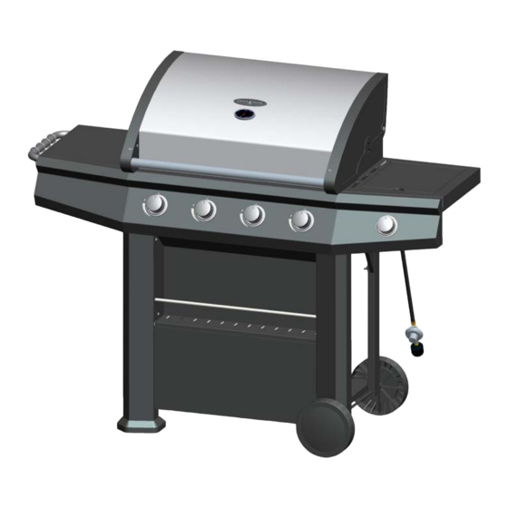
- Page 1 64,000 BTU GAS GRILL USER MANUAL MODEL NO.: SRGG41207 / TV NO.: 143758 Consumer: Retain this manual for future reference. Installer: Leave this manual with consumer. FOR OUTDOOR USE ONLY PLEASE CONTACT 1-866-814-0585 FOR ASSISTANCE DO NOT RETURN TO PLACE OF PURCHASE...
- Page 2 SAFETY INSTRUCTIONS DANGER If you smell gas: 1. Shut off gas to the appliance. 2. Extinguish any open flame. 3. Open lid. 4. If odor continues, keep away from the appliance and immediately call your gas supplier or your fire department. WARNING 1.
-
Page 3: Table Of Contents
TABLE OF CONTENTS SECTION ONE SECTION FOUR Safety Instructions………………………… 4 Operating Instructions………………..… Placement of the Grill……………………...8 Lighting Instructions…………………….. SECTION TWO SECTION FIVE Exploded View…………………………...… Using the Side Burner……………...…… Part List and Hardware List…………..…... Care & Maintenance ………………….… Assembly Instructions…….………..……..How to Replace Main Burner………...… Gas cylinder Installation Instruction….….. -
Page 4: Safety Instructions
SAFETY INSTRUCTIONS RECOGNIZED SAFETY SYMBOLS, WORDS AND LABELS DO NOT USE ALUMINUM FOIL TO LINE THE WARNING GRILL RACKS OR GRILL BOTTOM. This can Do not try lighting this appliance without first severely upset combustion airflow or trap excessive reading the “LIGHTING INSTRUCTIONS” section heat in the control area. - Page 5 SAFETY INSTRUCTIONS RECOGNIZED SAFETY SYMBOLS, WORDS AND LABELS WARNING: Always keep your face and body away from the burner when lighting. WARNING: IMPORTANT! BEFORE LIGHTING… Inspect the gas supply hose prior to turning the gas “ON”. If it is evident there is excessive abrasion or wear, or the hose is cut, it must be replaced prior to the grill being put into operation.
- Page 6 SAFETY INSTRUCTIONS DO NOT STORE ITEMS OF INTEREST TO TESTED ACCORDANCE WITH CHILDREN AROUND OR BELOW THE GRILL OR IN Z21.58-2007 / CSA 1.6- 2007, ANS Z1.58- 2008 / THE CART. NEVER ALLOW CHILDREN TO CRAWL CSA1.6a-2008 STANDARD OUTDOOR INSIDE OF THE CART. COOKING GAS APPLIANCES.
- Page 7 SAFETY INSTRUCTIONS When using the grill, do not touch the grill rack, Use only in well ventilated areas. Do not use in burner grate or immediate surroundings as these buildings, garages, sheds, breezeways or other such areas become extremely hot and could cause enclosed areas.
-
Page 8: Placement Of The Grill
PLACEMENT OF THE GRILL MINIMUM CLEARANCE: LOCATION 2’ Clearance from both sides of combustible When determining a suitable location take into material, and 3’ Clearance from the back. account concerns such as exposure to wind, proximity to traffic paths and keeping any gas supply lines as short as possible. -
Page 9: Exploded View
EXPLODED VIEW... -
Page 10: Part List And Hardware List
PART LIST 20. Axle 1. Lid Front right pole 2. Warming rack Rear right pole 3. Cooking grid 2pcs 23. Right transom 4. Flame tamer 5pcs Right side shelf 5. Main burner 5pcs Right side burner bowl 6. Grease tray Ignition pin 7. -
Page 11: Assembly Instructions
ASSEMBLY INSTRUCTIONS STEP 1 Insert the axle (20) through the front right pole (21) and rear right pole (22), secure them with 2pcs R-pins. R-pin 2pcs STEP 2 Attach 1pc pp washer, 2pcs D10 washers, 2pcs M10 nuts, 2pcs R-pins, 2pcs wheels (19) and 2pcs wheel caps (18) to the axle (20) and secure them in turn as shown. - Page 12 ASSEMBLY INSTRUCTIONS STEP 3 Insert the 4pcs pre-installed bolts on right transom (23) into the four key holes on front right pole (21) and rear right pole (22), secure them with 4pcs M5 x 12 wing bolts. Pre-installed bolts 4 pcs M5 X 12 wing bolt 4pcs STEP 4 Insert the 4pcs pre-installed bolts on left transom (13) into the 4 key holes on front left pole (15)
- Page 13 ASSEMBLY INSTRUCTIONS STEP 5 Insert the 4pcs pre-installed bolts on lower front panel (17) into the 4 key holes on front left pole (15) and front right pole (21), press down to position. STEP 6 1) Insert the 2pcs pre-installed bolts on bottom panel (35) into the 2 key holes on front left pole (15) and front right pole (21);...
- Page 14 ASSEMBLY INSTRUCTIONS STEP 7 Insert the 2pcs pre-installed bolts on condiment shelf (16) into the holes on top of front left pole (15) and front right pole (21), slide down and then place another 2pcs pre-installed bolts on condiment shelf (16) to position as shown. Then fix condiment shelf (#16) onto front left &...
- Page 15 ASSEMBLY INSTRUCTIONS STEP 9 Insert the ends of connection bar (37) into the holes on front left pole (15) and bottom panel (35) as illustrated. STEP 10 Place the grill body (30) onto the assembled cart, secure it with 4pcs D5 washersand 4pcs M5x12 wing bolts.
- Page 16 ASSEMBLY INSTRUCTIONS Step 11 1) Hang 4pcs towel hooks (10) on the side shelf handle (9). Install side shelf handle (9) and 2pcs side shelf handle bezels (8) to left side shelf (7) with 2pcs M6 x 12 bolts. 2) Install left side shelf (7) onto grill body (30) with 4pcs M5 x 16 bolts which are pre-installed on the grill body, not to tighten them instantly.
- Page 17 ASSEMBLY INSTRUCTIONS STEP 12 Insert the metal hose into the main burner gas pipe and screw to tighten with two wrenches. Caution: pay attention to metal hose positioning Main burner gas pipe WARNING: KEEP FLEXING OF THE METAL HOSE MINIMAL TO PREVENT FUTURE LEAKS. PERFORMA LEAK TEST WITH A SOAPY SOLUTION BEFORE USING.
- Page 18 ASSEMBLY INSTRUCTIONS STEP 13 Insert the end of ignition wire to the ignition pin (26) on the right side burner bowl (25). Note: manually adjust the gap between the ignition pin and the flame orifice around 3~5mm (0.1 - 0.2inch) to ensure proper ignition. Ignition wire Ignition pin Flame orifice...
- Page 19 ASSEMBLY INSTRUCTIONS STEP 14 Fix grease tray (6) onto the grill body (30) with 2pcs M5 x 12 bolts; install grease cup (34) into grease cup hanger (33) and then hang them onto the bottom of grease tray. M5x12 bolts 2pcs STEP 15 Place 4pcs flame tamers (4), 2pcs cooking grates (3) and 1pcs warming rack (2) into the grill body (30) in turn.
-
Page 20: Gas Cylinder Installation Instruction
GAS CYLINDER INSTALLATION INSTRUCTIONS STEP 1 Place gas cylinder (not included) into the hole at bottom panel (35). Life the cylinder fixing hook (36) to secure the gas cylinder. Gas cylinder STEP 2 1) Check to ensure that the valve of gas cylinder is securely turned off prior to making the connection. If not, turn the valve clockwise to turn it off. -
Page 21: Gas Hook-Up
GAS HOOK-UP Other cylinder may be acceptable for use with the Only the pressure regulator and hose assembly supplied appliance provided they are compatible with the appliance with the grill should be used. Any replacement pressure retention means. regulator and hose assembly must be those specified by the grill manufacturer. - Page 22 GAS HOOK-UP around the gas grill housing. This outdoor gas grill is not Open the cylinder valve fully (counterclockwise). intended to be installed in or on recreational vehicles Use a soapy water solution to check all connections and/or boats. for leaks before attempting to light the grill. See below.
- Page 23 GAS HOOK-UP When your gas grill is not in use, the gas must WARNING be turned off at the supply cylinders. Storage A strong gas smell or the hissing sound of gas of an outdoor cooking gas appliance indoors indicates a serious problem with your gas grill or the permissible only cylinder...
-
Page 24: Leak Testing
LEAK TESTING GAS FLOW CHECK GENERAL Each grill burner is tested and adjusted at the factory prior Although all gas connections on the grill are leak to shipment; however, variations in the local gas supply tested at the factory prior to shipment, a complete gas may make it necessary to adjust the burners, the flames tightness check must be performed at the installation site due to possible mishandling in shipment, or... -
Page 25: Installer Final Check
INSTALLER FINAL CHECK OPERATING INSTRUCTIONS Specified clearance maintained 2 feet from USING THE GRILL sides of combustibles, and 3 feet from the back. Grilling requires high heat for searing and proper All internal packaging removed. browning. Most foods are cooked at the “MAX” heat Knobs turn freely. -
Page 26: Lighting Instructions
LIGHTING INSTRUCTIONS WARNING: IMPORTANT! BEFORE LIGHTING… Inspect the gas supply hose prior to turning the gas “ON”. If it is evident there is excessive abrasion or wear, or the hose is cut, it must be replaced prior to Burner flames should be blue and stable with no the grill being put into operation. - Page 27 LIGHTING INSTRUCTIONS Keep a spray bottle of soapy water near the gas supply valve and check the connections before each use. Do not attempt to light the grill if odor of gas is present. Call for customer service 1-866-814-0585.
-
Page 28: Using The Side Burner
USING THE SIDE BURNER WARNING: IMPORTANT! MATCH LIGHTING THE SIDE BURNER 1. Open the lid to the side burner before lighting. 2. Turn the burner control knob to "OFF". USING THE SIDE BURNER 3. Strike and carefully place a match approximately 1/2" Inspect the gas supply hose prior to turning the gas (1 to 2 cm) from the burner. -
Page 29: Care & Maintenance
CARE & MAINTENANCE STAINLESS STEEL GREASE TRAY CLEANING The grease tray should be emptied and wiped down Under extreme conditions, stainless steel can rust and periodically and washed in a mild detergent and warm the rust may not be removable. These conditions may water solution. -
Page 30: How To Replace Main Burner
HOW TO REPLACE MAIN BURNER in burner image Ignition hole (upwards) 3. Line up burner and burner supporter and secure both parts by using M5x10 bolts and M5 nuts. M5 nut Nozzle 1 Line up burner and nozzle. 2. Assembly ignition hole of the burner downwards. -
Page 31: Trouble Shooting
TROUBLE SHOOTING SPIDER AND INSECT WARNING!!! 1. The smell of gas in conjunction with the burner Spiders and insects can nest in the burners of the grill flames appearing yellow. and cause the gas to flow from the front of the burner. 2. -
Page 32: Limited Warranty
ONE-YEAR LIMITED WARRANTY True Value Company warrants your gas grill to be free from manufacturer’s defects in workmanship or material under normal operating conditions for one (1) year from the original date of purchase. This warranty applies only to products sold at retail. True Value Company will, at its option, repair or replace free of charge any defective part, where the Purchaser has notified their Retailer within the warranty period.
Need help?
Do you have a question about the SRGG41207 and is the answer not in the manual?
Questions and answers