Table of Contents
Advertisement
Quick Links
Advertisement
Table of Contents

Related Manuals for Grill Zone SRGG42004


Summary of Contents for Grill Zone SRGG42004
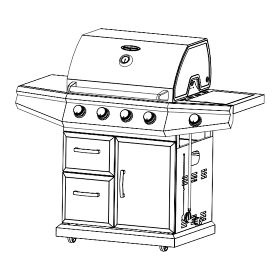
- Page 1 DELUXE PROPANE GAS GRILL USER MANUAL MODEL NO.: SRGG42004 / TV NO.: 108461 Consumer: Retain this manual for future reference. Installer: Leave this manual with consumer. FOR OUTDOOR USE ONLY PLEASE CONTACT 1-866-814-0585 FOR ASSISTANCE DO NOT RETURN TO PLACE OF PURCHASE...
- Page 2 SAFETY INSTRUCTIONS DANGER If you smell gas: 1. Shut off gas to the appliance. 2. Extinguish any open flame. 3. Open Lid. 4. If odor continues, keep away from the appliance and immediately call your gas supplier or your fire department. WARNING 1.
-
Page 3: Table Of Contents
TABLE OF CONTENTS SECTION ONE SECTION FOUR Safety Instructions ………………………4 Operating Instructions………….……..27 Placement of the Grill ……………………8 Lighting Instructions………………….. 28 SECTION TWO SECTION FIVE Exploded View……………………………9 Using the Side Burner………….………30 Part List and Hardware List ……………10 Care & Maintenance……………………31 Assembly Instructions…….………….…11 How to Replace Main Burner …………32 Trouble Shooting………………………..33 SECTION THREE... -
Page 4: Safety Instructions
SAFETY INSTRUCTIONS RECOGNIZED SAFETY SYMBOLS, WORDS AND LABELS DO NOT USE ALUMINUM FOIL TO LINE WARNING THE GRILL RACKS OR GRILL BOTTOM. Do not try lighting this appliance without first This can severely upset combustion airflow or reading the “LIGHTING INSTRUCTIONS” section trap excessive heat in the control area. - Page 5 SAFETY INSTRUCTIONS RECOGNIZED SAFETY SYMBOLS, WORDS AND LABELS WARNING: Always keep your face and body as far away from the burner as possible when lighting. WARNING: IMPORTANT! BEFORE LIGHTING… Inspect the gas supply hose prior to turning the gas “ON”. If there is evidence of cuts, wear, or abrasion, it must be replaced prior to use.
- Page 6 SAFETY INSTRUCTIONS TESTED ACCORDANCE WITH ANSI CHILDREN SHOULD NOT BE LEFT ALONE OR Z21.58-2007 / CSA 1.6-2007 STANDARD FOR UNATTENDED IN AN AREA WHERE THE GRILL IS OUTDOOR COOKING GAS APPLIANCES. THIS BEING USED. NEVER ALLOW THEM TO SIT, GRILL IS FOR OUTDOOR USE ONLY. STAND OR PLAY ON OR AROUND THE GRILL AT ANY TIME.
- Page 7 SAFETY INSTRUCTIONS When using the grill, do not touch the grill rack, burner Use only in well ventilated areas. Do not use in grate or immediate surroundings as these areas buildings, garages, sheds, breezeways or other such become extremely hot and could cause burns. Use enclosed areas.
-
Page 8: Placement Of The Grill
PLACEMENT OF THE GRILL CLEARANCE LOCATION To Non-Combustible Construction When determining a suitable location take into account concerns such as exposure to wind, MINIMUM CLEARANCE: proximity to traffic paths and keeping any gas supply 2’ clearance from both sides of combustible lines as short as possible. -
Page 9: Exploded View
EXPLODED VIEW... -
Page 10: Part List And Hardware List
PART LIST 1. Lid, 1 pc 25. Grease tray, 1 pc 2. Thermometer, 1 pc 26. Grill body, 1 pc 3. Lid handle end cap, 2 pcs 27. Right side burner control panel, 1 pc 4. Lid handle, 1 pc 28. -
Page 11: Assembly Instructions
ASSEMBLY INSTRUCTIONS STEP 1 Fix (12) top drawer front panel onto (40) top drawer body with 5pcs M5 x 12 bolts. STEP 2 Fix (13) lower drawer front panel onto (42) lower drawer body with 5pcs M5 x 12 bolts. -
Page 12: Place (35) Cart Bottom Panel Sideway, Fix (10 & 31) Cart Left & Right Panels Onto Cart Bottom Panel With 10Pcs M6 X
ASSEMBLY INSTRUCTIONS STEP 3 Turn over (35) cart bottom panel, screw 1 pc (45) locking caster and 1pc (47) non-locking caster to the right side of (35) cart bottom panel, and fix 2pcs (46) wheels on the left side with 8pcs M6 x 12 bolts. STEP 4 Place (35) cart bottom panel sideway, fix (10 &... - Page 13 ASSEMBLY INSTRUCTIONS STEP 5 Fix (32) cart rear panel to (10 & 31) cart left & right panels, (35) cart bottom panel with 6pcs ST5 x 8 bolts. STEP 6 Place the hinges of (44) cart door into the holes on (35) cart bottom panel and (39) cart horizontal bar, fix (39) cart horizontal bar to the front legs of (10 &...
- Page 14 ASSEMBLY INSTRUCTIONS STEP 7 Place the drawer frame inside the cart, fix it onto (35) cart bottom panel and (39) cart horizontal bar with 3pcs M5 x 12 bolts, then onto (32) cart rear panel with 2pcs M6 x 12 bolts. NOTE: KEEP all bolts half loosen during the assembly of this step until the grill body assembly is placed into the position correctly.
- Page 15 ASSEMBLY INSTRUCTIONS STEP 8 Place the top & lower drawers into the cart, and adjust the drawer frame to fix these two drawers well. STEP 9 Place grill body assembly flatly onto the cart assembly. Open the lid, line up and fix the grill body and cart assembly with 8pcs M6 x 20 bolts from inside of the fire bowl.
- Page 16 ASSEMBLY INSTRUCTIONS STEP 10 Screw 4pcs M6 x 16 bolts with washer onto four legs, keep the bolts half loosen. STEP 11 Place the left & right side shelf assembly to two sides of the cart assembly, then tighten the 4pcs M6 x 16 bolts with washer.
- Page 17 ASSEMBLY INSTRUCTIONS STEP 12 Fix the left & right side shelf assembly to main burner control panel with 4pcs M6 x 12 bolts. STEP 13 Fix the left & right side shelf assembly to grill body with 4pcs M6 x 20 bolts.
- Page 18 ASSEMBLY INSTRUCTIONS STEP 14 a) Insert side burner valve assembly into the hole on (27) right side burner control panel, fix (38) control knob bezel onto side burner valve assembly with 2pcs M4 x 12 bolts, then install (37) control knob onto the shaft of side burner valve assembly. b) Insert (22) right side burner onto (21) right side burner fire bowl, insert the nozzle of side burner valve assembly into the injection pipe of (22) right side burner, then fix the right side...
- Page 19 ASSEMBLY INSTRUCTIONS STEP 15 Insert the electric wire into the connector of right side burner valve assembly. NOTE: Adjust the distance between the Ignition Pin and Flame Orifice to be 3~5mm in case of ignition failure.
- Page 20 ASSEMBLY INSTRUCTIONS STEP 16 Open the lid, place (16) flame tamer, (15) cooking grate and (14) warming rack into (26) grill body respectively. Place right side burner rack onto right side burner bowl.
- Page 21 STEP 17 1) Place gas cylinder (not included) into the hole at (35) cart bottom panel. 2) Insert (34) cylinder locking bolt into the hole at the back of cart bottom panel. Assembled Grill as following illustrated. Gas Cylinder Placement (NOT INCLUDED) 1) Check to ensure that the valve of gas cylinder is securely shut off prior to the connection.
-
Page 22: Gas Hook-Up
2) Connect the hose and regulator assembly to the gas cylinder. Turn the regulator clockwise to make sure it’s securely tightened. Shut off gas supply by rotating valve of gas cylinder clockwise. regulator rotating it by rotating Gas cylinder clockwise. GAS HOOK-UP Only the pressure regulator and hose assembly Main Manifold operating pressure: 11”... - Page 23 GAS HOOK-UP To disconnect LP gas cylinder: Never connect an unregulated LP gas cylinder to your 1. Turn the burner valves off. gas grill. The gas regulator assembly supplied with 2. Turn the cylinder valve off fully (turn clockwise to your gas grill is adjusted to have an outlet pressure of stop).
- Page 24 GAS HOOK-UP WARNING The regulator and hose assembly must be A strong gas smell or the hissing sound of gas inspected before each use of the grill. If there indicates a serious problem with your gas grill or the is excessive abrasion or wear or if the hose is LP gas cylinder.
-
Page 25: Leak Testing
LEAK TESTING GENERAL GAS FLOW CHECK Although all gas connections on the grill are leak Each grill burner is tested and adjusted at the factory prior tested at the factory prior to shipment, a complete gas to shipment; however, variations in the local gas supply tightness check must be performed at the installation may make it necessary to adjust the burners, the flames site due to possible mishandling in shipment, or... -
Page 26: Installer Final Check
INSTALLER FINAL CHECK Specified clearance maintained 2 feet from Unit tested and free of leaks. sides of combustibles, and 3 feet from the back. User informed of gas supply shut off valve location. All internal packaging removed. Knobs turn freely. Burners are tight and sitting properly on orifices. -
Page 27: Operating Instructions
OPERATING INSTRUCTIONS USING THE GRILL: Grilling requires high heat for searing and proper browning. Most foods are cooked at the “IGNITE/MAX” heat setting for the entire cooking time. However, when grilling large pieces of meat or poultry, it may be necessary to turn the heat to a lower setting after the initial browning. -
Page 28: Lighting Instructions
LIGHTING INSTRUCTIONS WARNING: IMPORTANT! Burner flames should be blue and stable with no yellow tips, excessive noise, or lifting. If any of these conditions exist, call our customer service line. If the BEFORE LIGHTING… Inspect the gas supply hose prior to turning the gas flame is yellow, it indicates insufficient air. - Page 29 LIGHTING INSTRUCTIONS Keep a spray bottle of soapy water near the gas supply valve and check the connections before each use.
-
Page 30: Using The Side Burner
Do not attempt to light the grill if odor of gas is present. Call for customer service 1-866-814-0585 USING THE SIDE BURNER MATCH LIGHTING THE SIDE BURNER WARNING: IMPORTANT! 1. Open the lid to the side burner before lighting. 2. Turn the burner control knob to "OFF". USING THE SIDE BURNER 3. -
Page 31: Care & Maintenance
CARE & MAINTENANCE STAINLESS STEEL GREASE TRAY CLEANING Under extreme conditions, stainless steel can rust The grease tray should be emptied and wiped down and may not be removable. These conditions may periodically and washed in a mild detergent and warm become more prevalent in coastal areas. -
Page 32: How To Replace Main Burner
HOW TO REPLACE MAIN BURNER Main burner image Ignition hole (upwards) Line up burner and burner supporter and secure both parts by using M6 x 12 bolts. -
Page 33: Trouble Shooting
TROUBLE SHOOTING SPIDER AND INSECT WARNING!!! Spiders and insects can nest in the burners of the grill and cause the gas to flow from the front of the burner. This is a very dangerous condition, which can cause a fire to occur behind the valve panel, thereby damaging the grill and making it unsafe to operate. -
Page 34: Limited Warranty
Grill takes a long time to -- Normal preheat 500-600 degrees, takes about 10-15 min. Cold weather and wind may preheat. effect your preheat time. Volcanic rock and Briquettes should not be used in this BBQ. Burner flames are not light -- Too much or not enough air mixes for the flame. - Page 35 exclusion may not apply to you. This warranty gives you specific legal rights. You may also have other rights, which vary from province to province. If you require service, please first see the “Troubleshooting” section of the Owner’s Manual. Additional assistance can be found by calling our toll-free customer service line at 1-866-814-0585, Monday to Friday from 9:00 AM to 5:00 PM (EST).
Need help?
Do you have a question about the SRGG42004 and is the answer not in the manual?
Questions and answers