Table of Contents
Advertisement
Quick Links
NOVEMBER 1994
IC221A-R3
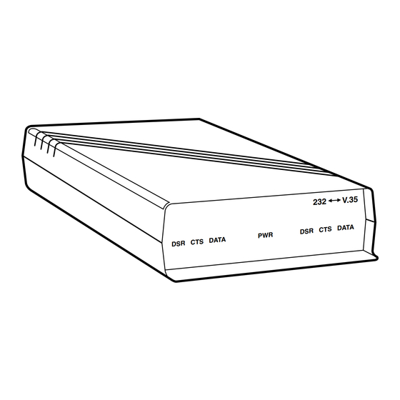
RS-232 ↔ V.35 Interface Converter
V .3 5
2 3 2
D A T A
D S R C T S
P W R
D A T A
D S R C T S
CUSTOMER
Order toll-free in the U.S.: Call 877-877-BBOX (outside U.S. call 724-746-5500)
FREE technical support 24 hours a day, 7 days a week: Call 724-746-5500 or fax 724-746-0746
SUPPORT
Mailing address: Black Box Corporation, 1000 Park Drive, Lawrence, PA 15055-1018
INFORMATION
Web site: www.blackbox.com • E-mail: info@blackbox.com
Advertisement
Table of Contents

Related Manuals for Black Box RS-232


Summary of Contents for Black Box RS-232
- Page 1 Order toll-free in the U.S.: Call 877-877-BBOX (outside U.S. call 724-746-5500) FREE technical support 24 hours a day, 7 days a week: Call 724-746-5500 or fax 724-746-0746 SUPPORT Mailing address: Black Box Corporation, 1000 Park Drive, Lawrence, PA 15055-1018 INFORMATION Web site: www.blackbox.com • E-mail: info@blackbox.com...
- Page 2 RS-232 ↔ V.35 INTERFACE CONVERTER FEDERAL COMMUNICATIONS COMMISSION RADIO FREQUENCY INTERFERENCE STATEMENT This equipment generates, uses, and can radiate radio frequency energy and if not installed and used properly, that is, in strict accordance with the manufacturer's instructions, may cause interference to radio communication.
-
Page 3: Table Of Contents
RS-232 ↔ V.35 INTERFACE CONVERTER CONTENTS 1.0 SPECIFICATIONS ............................4 2.0 INTRODUCTION ............................5 3.0 INSTALLATION............................6 DIP Shunt Settings........................7 Terminal Ready Option Strap W7....................8 LEDs ..............................8 4.0 GROUND STRAP AND PIN CONNECTIONS ..................9 Ground Strap ..........................9 Pin Connections..........................10... -
Page 4: Specifications
MTBF — 125,905 hours Interface — RS-232, V.35; both interfaces DTE/DCE selectable Connectors — RS-232: DB25 male; V.35: (1) 34-pin female "M" block Environmental — Maximum storage temperature: 70° C Maximum operating temperature: 50° C Power — 115 VAC, 60 Hz, 13 watts (230-VAC model available on request) Standalone: 2.3"H x 8"W x 11.9"D (5.8 x 20.3 x 30.2 cm) -
Page 5: Introduction
Figure 2-1 shows a typical application of the bidirectional conversion of all the commonly used RS-232↔V.35 Interface Converter. V.35 and RS-232 signals. The unit is designed for use with one port configured as Data Terminal Equipment (DTE) and the other port as Data Communications Equipment (DCE). -
Page 6: Installation
Figure 3-1. power module into an AC outlet until after the 1.Attach the cable from the RS-232 device to the DIP shunts and Strap W7 are set as explained in 25-pin male connector (J1) on the rear panel of Sections 3.1 and 3-2. -
Page 7: Dip Shunt Settings
DIP shunt settings located inside the unit on the printed circuit board. Figure 3-1 shows how to configure the RS-232 side of the converter for DCE and the V.35 side as DTE. This configuration should be used when connecting RS-232 DTE equipment to V.35 DCE equipment, such as a computer to a... -
Page 8: Terminal Ready Option Strap W7
• Data — Indicates Tx data (Pins P and S) V.35 port configured as DCE mode, a jumper from B to C forces DTR (Pin 20) out of the RS-232 port The three right-most LED indicators show the state (default). A jumper between A and B passes of the INCOMING RS-232 signals. -
Page 9: Ground Strap And Pin Connections
CHAPTER 4: Ground Strap and Pin Connections 4.0 Ground Strap and Pin Connections 4.1 Ground Strap Signal grounds (Pin 7 on the RS-232 interface and Pin B on the V.35 interface) are connected to each other but not connected to chassis ground (Pin A). -
Page 10: Pin Connections
RS-232 ↔ V.35 INTERFACE CONVERTER 4.2 Pin Connections The pin connections for RS-232 DCE to V.35 DTE are shown below. - Page 11 CHAPTER 4: Ground Strap and Pin Connections The pin connections for RS-232 DTE to V.35 DCE are shown below. (V.35 DSR LED) NOTE PIN 20 (DTR) IS PULLED HIGH WITH W7 IN THE POSITION SHOWN.
- Page 12 © Copyright 1994. Black Box Corporation. All rights reserved. 1000 Park Drive • Lawrence, PA 15055-1018 • 724-746-5500 • Fax 724-746-0746...
Need help?
Do you have a question about the RS-232 and is the answer not in the manual?
Questions and answers