Advertisement
Quick Links
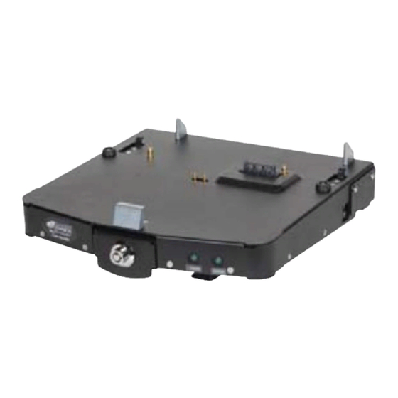
INSTALLATION INSTRUCTIONS
Product
GD8000 Docking Station
7160-0194-01, -02, -03, -04, -05, -06
This instruction sheet is for the GD8000
docking station.
*These instructions are for the docking station only. For instructions on features, set-up
and operation of the GD8000 computer, please refer to the manuals provided by General
Dynamics Itronix with the computer.
** This docking station is designed to be used with a variety of Gamber-Johnson mounting
systems. Installation instructions for other Gamber-Johnson products are provided with
each individual product.
IMPORTANT SAFETY INFORMATION for
Safety is dependent on the proper installation and servicing of this docking station. It is
important to read and follow all instructions before installing this product.
To properly install a Gamber-Johnson docking station you must have a good understanding
of automotive electrical procedures and systems, along with proficiency in the installation
and service of aftermarket vehicle equipment.
There are no adjustments required at any time of the electrical components within the
docking station. Opening the docking station will void the product warranty.
Product Mounting Disclaimer
Gamber-Johnson is not liable under any theory of contract or tort law for any loss, damage, personal in jury, special, incidental or consequential damages for personal injury or other damage
of any nature arising directly or indirectly as a result of the improper installation or use of its products in vehicle or any other application. In order to safely install and use Gamber-Johnson
products full consideration of vehicle occupants, vehicle systems (i.e., the location of fuel lines, brakes lines, electrical, drive train or other systems), air-bags and other safety equipment is
required. Gamber-Johnson specifically disclaims any responsibility for the improper use or installation of its products not consistent with the original vehicle manufactures specifications
and recommendations, Gamber-Johnson product instruction sheets, or workmanship standards as endorsed through the Gamber-Johnson Certified Installer Program.
If you need assistance or have questions, call Gamber-Johnson at 1-800-456-6868
Revision
Rev. C
INSTALLERS
Form #
INST-437
Page 1 of 6
Advertisement

Related Manuals for Gamber Johnson GD8000


Summary of Contents for Gamber Johnson GD8000
-
Page 1: Installation Instructions
Gamber-Johnson is not liable under any theory of contract or tort law for any loss, damage, personal in jury, special, incidental or consequential damages for personal injury or other damage of any nature arising directly or indirectly as a result of the improper installation or use of its products in vehicle or any other application. In order to safely install and use Gamber-Johnson products full consideration of vehicle occupants, vehicle systems (i.e., the location of fuel lines, brakes lines, electrical, drive train or other systems), air-bags and other safety equipment is... -
Page 2: Pre-Installation Recommendations
PRE-INSTALLATION RECOMMENDATIONS Conduct a "Bench Test" Gamber-Johnson strongly advises a "bench test" be conducted to verify that all electronic and software issues are resolved prior to installation: 1. Make sure computer is operational by itself. -
Page 3: Power Supply Information
If a timing device is used follow the instructions of the manufacturer of that device. It must be wired in-line with the supply voltage (V+) to the docking station. If you have any installation questions, please call Gamber-Johnson customer support at 1-800-456-6868... - Page 4 Figure 2 Ground to Vehicle Chassis 14 AWG (black wire) J1128 TYPE GPT Panduit #BSN14-C Butt Splice connects to black lead from dock Panduit #BSN14-C Butt Splice connects to 10" red lead from dock Fuse Vehicle Battery 14 AWG (red wire) J1128 TYPE GPT Connect in-line fuse holder to lead wire using Panduit #BSN14-C Butt Splice connectors...
- Page 5 Figure 5 3. Push the latch handle in until the latch catches and holds the handle. You should hear an audible click when the latch engages. (See Figure 5.) The push button latch can be locked for added security. Align notch with hook Undocking and removing a computer (Without LAN Usage) from the vehicle dock...
-
Page 6: External Antenna Options
External Antenna Options The GD8000 vehicle dock gives you the option of blocking either one or both of the external antenna connectors from contacting the mechanical RF switches in the computer. This may be required if the external antennas are not yet available or you do not want to switch to an external antenna.