Sign In
Upload
Download
Table of Contents
Contents
Add to my manuals
Delete from my manuals
Share
URL of this page:
HTML Link:
Bookmark this page
Add
Manual will be automatically added to "My Manuals"
Print this page
×
Bookmark added
×
Added to my manuals
Manuals
Brands
Effekta Manuals
Inverter
ES2200
Operating manual
Effekta ES2200 Operating Manual
Photovoltaic solar inverter series es
Hide thumbs
1
2
Table Of Contents
3
4
5
6
7
8
9
10
11
12
13
14
15
16
17
18
19
20
21
22
23
24
25
26
27
28
29
30
31
32
33
34
35
36
37
38
39
40
41
42
43
44
45
46
47
48
49
50
51
52
53
54
55
56
57
58
59
60
61
62
63
64
65
66
67
68
69
70
71
72
73
74
75
76
77
78
79
80
81
82
83
84
page
of
84
Go
/
84
Contents
Table of Contents
Troubleshooting
Bookmarks
Table of Contents
Table of Contents
1 Introduction
Foreword
Validity
Storage
Symbols in this Manual
Information Obligation
Warranty Conditions
Limitation of Liability
Transport and Storage
Positioning
2 Safety Instructions
Introduction
Proper Use
Avoiding Personal Injury / Property Damage
Protecting the Environment
Connection
Advice about Specific Dangers
Operation
Working with PV Modules
Maintenance, Service and Malfunctions
Advice about Connecting to the Mains Power
3 Device Description
Dimensions
Display and Connections
4 Assembly
Assembly of the Wall Mounting
Ambient Conditions for Assembly
Assembling Photovoltaic Solar Inverters
5 Electrical Installation
Connecting AC Power Cable
Connecting PV Module
6 Control Panel
7 Commissioning
Starting Device for the First Time
Country Settings, Operating Mode Settings and ID Settings
Country/Operating Mode/ID Settings
Commissioning the Photovoltaic Solar Inverter
Checking Measurement Readings and Numbers
Operating States of the Photovoltaic Solar Inverter
8 Communication Interfaces
Standard Communication Interface
Solar-Log TM
Optional Data Cards
9 Status Diagnosis and Troubleshooting
Error Codes and Explanations
Mains Error Alarm Codes and Explanations
10 Service
11 Technical Data
Device Specifications
ES2200 / ES3300 Block Diagram
ES4200 / ES5000 Block Diagram
Scope of Delivery / (Optional) Accessories
12 Declaration of Conformity
Advertisement
Quick Links
1
Error Codes and Explanations
2
Device Specifications
3
Es4200 / Es5000 Block Diagram
Download this manual
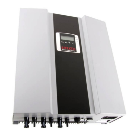
Photovoltaic Solar Inverter Series ES
ES2200 / ES3300 / ES4200 / ES5000
Operating Manual V. 3.2
Article number:
Translation of the original Operating Manual
SLWRABSI2K0Wx000
SLWRABSI3K0Wx000
SLWRABSI4K0Wx000
SLWRABSI5K0Wx000
Table of
Contents
Previous
Page
Next
Page
1
2
3
4
5
Advertisement
Table of Contents
Need help?
Do you have a question about the ES2200 and is the answer not in the manual?
Ask a question
Questions and answers
Subscribe to Our Youtube Channel
Related Manuals for Effekta ES2200
Inverter Effekta ES3300 Operating Manual
Photovoltaic solar inverter series es (84 pages)
Inverter Effekta ES5000 Operating Manual
Photovoltaic solar inverter series es (84 pages)
Inverter Effekta ES4200 Operating Manual
Photovoltaic solar inverter series es (84 pages)
Inverter Effekta AX M2 Series User Manual
Solar inverter 3-5kw (132 pages)
Inverter Effekta KS5 Series Installation And Operation Manual
Grid-connected inverter (36 pages)
Inverter Effekta 10A/WRSL-12-0700 Instruction Manual
Pure sine wave inverter 12v / 24v / 48v / 700 watt / 1000 watt (32 pages)
Inverter Effekta 10A/WRSL-12-1500 Instruction Manual
Pure sine wave inverter 12v / 24v / 48v 1500 watt / 2000 watt (30 pages)
Inverter Effekta 10A/WRSL-12-3000 Instruction Manual
Pure sine wave inverter 12v / 24v / 48v 3000 watt (32 pages)
This manual is also suitable for:
Es3300
Es5000
Es4200
Table of Contents
Print
Rename the bookmark
Delete bookmark?
Delete from my manuals?
Login
Sign In
OR
Sign in with Facebook
Sign in with Google
Upload manual
Upload from disk
Upload from URL


Need help?
Do you have a question about the ES2200 and is the answer not in the manual?
Questions and answers