
Related Manuals for Effekta 10A/WRSL-12-3000


Summary of Contents for Effekta 10A/WRSL-12-3000
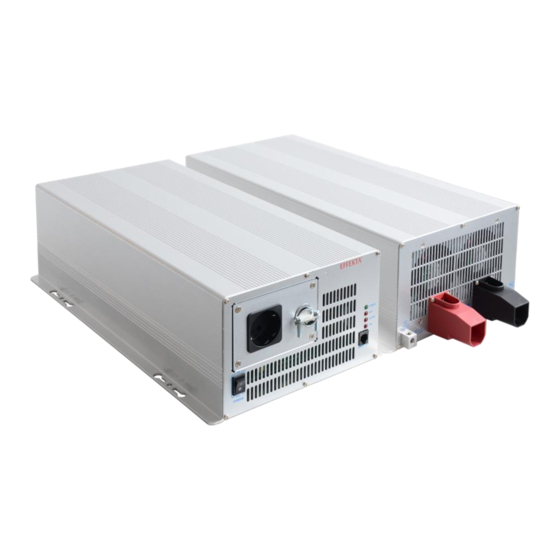
- Page 1 PURE SINE WAVE INVERTER 12V / 24V / 48V 3000 Watt Instruction Manual Item number: 10A/WRSL-12-3000, 10A/WRSL-24-3000, 10A/WRSL-48-3000 Version 1.0 / March 2020...
-
Page 2: Table Of Contents
SINE WAVE INVERTER WRSL-xx-3000 Manual Content Introduction Presentation Warranty conditions Limitation of liability Safety General safety instruction Transport ans storage Placement Connection Operation Handling batteries Maintenance, servicing and faults System description Display and handling elements on the front side 5.1.1 Handling elements of the inverter 5.1.2 Display elements of the inverter... - Page 3 SINE WAVE INVERTER WRSL-xx-3000 Manual Maintenance and service 11.1 Service hotline: Technical data 12.1 Specifications 12.1.1 Model 1500W 12.1.1 Model 2000W Requirements for the declearation of conformity page 3 of 32 WRSL series...
-
Page 4: Introduction
SINE WAVE INVERTER WRSL-xx-3000 Manual 1 Introduction This manual is intended to provide basic information about the inverter equipment, namely the functional principle, use of the various functions and the procedure to follow in the event of faults. In addition, this manual contains information on transportation and storage as well as handling and installation of the equipment. -
Page 5: Presentation
All trademarks used are the property of their respective owners. ® EFFEKTA is a registered trademark of EFFEKTA Regeltechnik GmbH. We reserve the right to make technical and visual changes, and we are not liable for typographical errors (E&OE). page 5 of 32... -
Page 6: Warranty Conditions
EFFEKTA GmbH does not give any express or implied warranties in relation to this equipment and its quality, performance, merchantability or suitability for a specific purpose. -
Page 7: Limitation Of Liability
3.1 Limitation of liability Compensation claims are excluded unless they are based on deliberate acts or gross negligence of EFFEKTA GmbH or its employees. Liability under the Product Liability Act remains unaffected. Under no circumstances will we be held liable for: Claims for losses or damage made by third parties against you. -
Page 8: Safety
The packing has not a fall protection, therefore all falled down equipments have to be checked by EFFEKTA bevore installation. 4.3 Placement Do not install the SI where is burning damp, e.g. fuel stock or motor rooms, etc. -
Page 9: Connection
SINE WAVE INVERTER WRSL-xx-3000 Manual Keep a minimum distance of 10cm from the vents of the front side and back side of the equipment to other objects, to avoid an air blockage and an overheat. Ensure that the vents of the equipment are not blocked, e.g by absorbed paper, tissue, etc. -
Page 10: Operation
SINE WAVE INVERTER WRSL-xx-3000 Manual The sum of the earth fault currents of all consumer loads connected to the SI must not exceed 3.5mA. Keep the connecting cables as short as possible and always lay these correctly. Avoid the dangers of laying connecting cables in locations where they may be tripped over, crushed or torn open etc. -
Page 11: Maintenance, Servicing And Faults
SINE WAVE INVERTER WRSL-xx-3000 Manual 4.7 Maintenance, servicing and faults Warning – danger of electric shocks. Even after pushing the Power switch or after disconnecting the battery supply, parts of the inverter can have dangerous voltage potential. Work on batteries may only be performed and monitored by personnel with appropriate technical knowledge about the required precautions. -
Page 12: System Description
SINE WAVE INVERTER WRSL-xx-3000 Manual 5 System description In this chapter you will be confronted with the corresponding equipment elements and get instructions for the handling and get information concerning the connecting of the equipment. 5.1 Display and handling elements on the front side All handling and display elements, which are necessary for normal service, are on the front side. -
Page 13: Display Elements Of The Inverter
SINE WAVE INVERTER WRSL-xx-3000 Manual 5.1.2 Display elements of the inverter Generally the display elements are first active, when the inverter is switched-on (ON). The Status – LED´s indicated the condition from Inverter. Status - LED: RJ45 socket (REMOTE PORT) On remote control (additional accessory) to query the operating status or to control it with the remote control. -
Page 14: Elements On The Back Side
SINE WAVE INVERTER WRSL-xx-3000 Manual 5.2 Elements on the back side Fig.. 2: back side view WRSL 3000 Connect 12V / 24V / 48V batteries, or others, with 12V / 24V / 48V Battery terminal energy sources. blocks: + is positive,- is negative. When wiring the internal fuse will blow and can damage the inverter forever. -
Page 15: Elements On The Side Panel
SINE WAVE INVERTER WRSL-xx-3000 Manual Keep a minimum distance of 10cm from the vents of the front side and Ventilation opening: back side of the equipment to other objects, to avoid an air blockage and an overheat. Ensure that the vents of the equipment are not blocked, e.g by absorbed paper, tissue, etc. -
Page 16: Storage And Unpacking
SINE WAVE INVERTER WRSL-xx-3000 Manual 6 Storage and unpacking 6.1 Storage of the inverter If the equipment is not installed immediately, the following should be observed: The equipment and accessories must always be left and stored in the original packaging. The recommended ambient storage temperatures are: +0°C...+40°C. -
Page 17: Installation And Connecting Of The Inverter
SINE WAVE INVERTER WRSL-xx-3000 Manual 7 Installation and connecting of the inverter All requirements in the technical data regarding environmental and operating conditions must be observed to ensure trouble-free functioning of the UPS. The following must be observed when setting up / installing the SI: Avoid extremes of temperature and atmospheric humidity Observe the specified installation location and only mount the equipment using the screw-in positions (fig. -
Page 18: A) Wrsl-0Xx-1500/2000
SINE WAVE INVERTER WRSL-xx-3000 Manual a) WRSL-0xx-3000 Fig. 3: screw-in positions and external dimension page 18 of 32 WRSL series... -
Page 19: Connecting The Inverter
SINE WAVE INVERTER WRSL-xx-3000 Manual 7.1 Connecting the inverter - Earth connection: Connect the protective earth conductor PE of the inverter with the grounding point of the place of installation, by using an isolated line with a minimum cable cross-section of 10qmm2. Ensure that the connections are fixed and safe, the lines have to be laid in one piece and must not be extended! Depending on place of installation as a precaution the inverter... - Page 20 SINE WAVE INVERTER WRSL-xx-3000 Manual Fig. 4: terminal connection Danger ! The terminal cover may only be opened when the battery connection is disconnected. The connection to the terminal strip must only be carried out by authorised specialist personnel. Work steps for terminal connection: 1.
- Page 21 SINE WAVE INVERTER WRSL-xx-3000 Manual - Battery connection Fig. 5: battery connection Work steps for terminal connection: 1. screw the battery cable with cable eyes M8 (not included in the scope of delivery) to the busbars (Fig.5) with the correct polarity. 2.
-
Page 22: Connection Sequence
SINE WAVE INVERTER WRSL-xx-3000 Manual Connection Item no. Cable cross-section Inline fuse figures: 240qmm 2 WRS-012-3000 400A 120qmm 2 WRS-024-3000 200A 50qmm 2 WRS-048-3000 100A The fuse has to be installed at the positive cable. A bigger cable cross-section decreases voltage decline at the cable. Just use copper cable of high quality and keep the cable length as short as possible (max. -
Page 23: Operating And Controlling The Equipment
SINE WAVE INVERTER WRSL-xx-3000 Manual 8 Operating and controlling the equipment Frequency Baud Outpu (Hz) rate voltag 8.1 Basic settings 2400 200 VA Set up the basic parameters (sideways) before installation. 4800 220 VA 9600 230 VA 19200 240 VA Never change the settings during operation. -
Page 24: Led`s
SINE WAVE INVERTER WRSL-xx-3000 Manual 8.1.1 LED`s POWER: The Inverter ist in function. OLP = Overload protection: The output voltage is beyond the nominal voltage. OVP/UVP = Overvoltage/Undervoltage protection: The DC input voltage has exceeded or underrun the allowed limit and has been switched-off automatically. -
Page 25: Instructions For Using Of The Inverter
SINE WAVE INVERTER WRSL-xx-3000 Manual 8.2 Instructions for using of the inverter The user of this inverter always has to comply with the instructions of this manual. The user is only allowed to undertake the following steps and just with great care: Use the buttons: switching-on and switching-off the SI. -
Page 26: Setting-Up Of The Inverter
SINE WAVE INVERTER WRSL-xx-3000 Manual 9 Setting-up of the inverter To guarantee a perfect setting-up, please follow the instructions: 1. Connect the inverter with the earth connection. 2. Make sure that the Power switch is in position “OFF”. 3. Connect the DC supply at the back side of the SI.. Always compare before connecting, the indicated voltage of the inverter and teh battery. -
Page 27: Troubleshooting
SINE WAVE INVERTER WRSL-xx-3000 Manual 10 Troubleshooting Just authorized persons are allowed to do troubleshooting at the inverter. Do not open or decunstruct the inverter, the trial to do troubleshooting by yourself can cause danger of electric shocks or fire. In case of a failure massage on the LED´s (see 8.1.1) the problem (overvoltage, overload or overtemperature) has to be solved. - Page 28 If it is not possible for you to get in touch by telephone, we have set up an e- mail contact address for you: ups@effekta.com In addition, you can contact the department or subsidiary you need directly via the following Internet address: http://www.effekta.com/html/kontakt.html...
- Page 29 SINE WAVE INVERTER WRSL-xx-3000 Manual 12 Technical data 12.1 Specifications 12.1.1 Model 1500W Specifications Model 1500W Equipment WRSL-012-1500 WRSL-024-1500 WRSL-048-1500 Duration output power 1500W Max. output power 1650W (3 min.) Input voltage Input voltage window 10-16VDC 20-32VDC 42-62VDC Warning message DC input 15.5VDC 31VDC 61VDC...
- Page 30 SINE WAVE INVERTER WRSL-xx-3000 Manual 12.1.1 Model 2000W Specifications Modell 2000W Equipment WRSL-012-2000 WRSL-024-2000 WRSL-048-2000 Duration output power 2000W Max. output power 2300W (3 Min.) Input voltage Input voltage window 10-16VDC 20-32VDC 42-62VDC Warning message DC input 15,5VDC 31VDC 61VDC overvoltage Switching-off DC input 16,0VDC...
- Page 31 SINE WAVE INVERTER WRSL-xx-3000 Manual 13 Requirements for the declearation of conformity An EU declaration of conformity for CE-labelled products can be requested from the following address: EFFEKTA Regeltechnik GmbH Rheinwaldstr. 34 78628 Rottweil GERMANY Tel.-no.: 0049 / (0) 741–17451-0...
- Page 32 SINE WAVE INVERTER WRSL-xx-3000 Manual Rheinwaldstraße 34, 78628 Rottweil Tel: + 49 (0) 74 1 / 1 74 51 - 0 Mail: info@effekta.com page 32 of 32 WRSL series...
Need help?
Do you have a question about the 10A/WRSL-12-3000 and is the answer not in the manual?
Questions and answers