HydroTherm HeatNet KN2 Manual
Kn series gas-fired direct vent cast iron boilers heatnet manual
Hide thumbs
Also See for HeatNet KN2:
- Installation and operation instructions manual (56 pages) ,
- User manual (48 pages) ,
- Control manual (32 pages)
Table of Contents
Advertisement
This manual is intended only for use by a qualified heating installer/technician. Read and follow this manual, all
supplements and related instructional information provided with the boiler. Install, start and service the boiler only
in the sequence and methods given in these instructions. Failure to do so can result in severe personal injury,
death or substantial property damage.
Do not use the boiler during construction. Construction dust and particulate, particularly drywall dust, will cause
contamination of the burner, resulting in possible severe personal injury, death or substantial property damage.
The boiler can only be operated with a dust-free air supply. Follow the instruction manual procedures to duct air to
the boiler air intake. If the boiler has been contaminated by operation with contaminated air, follow the instruction
manual guidelines to clean, repair or replace the boiler if necessary.
Affix these instructions near to the boiler. Instruct the building owner to retain the instructions for future use by a
qualified service technician, and to follow all guidelines in the User's Information Manual.
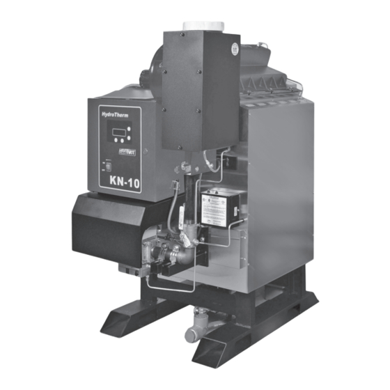
Models KN-6 through KN-30
Control adjustment and operation instructions
for Hydrotherm firmware version 3.4
This instruction manual applies only to Hydrotherm
firmware version 3.4 on version 2.x control
boards. Current firmware is backwards compatible
with version 1.x boards, but some current features
may not be available. To replace firmware on an
existing boiler, contact the factory to obtain the
original firmware file or for assistance in applying
current firmware to an older version control board.
Also read and follow:
KN-Series Gas Boiler Installation
and Operating Instructions
Copyright 2011 Mestek, Inc
KNCT -1011
manual
.
Advertisement
Table of Contents

Related Manuals for HydroTherm HeatNet KN2


Summary of Contents for HydroTherm HeatNet KN2
- Page 1 Models KN-6 through KN-30 manual Control adjustment and operation instructions for Hydrotherm firmware version 3.4 This instruction manual applies only to Hydrotherm firmware version 3.4 on version 2.x control boards. Current firmware is backwards compatible with version 1.x boards, but some current features may not be available.
-
Page 2: Table Of Contents
TABLE OF CONTENTS HeatNet Control REV 3.47-1 TABLE OF CONTENTS TABLE OF CONTENTS ..........................2 Introduction ............................... 4 KN-S ..............................4 ERIES ONTROL Features & Specifications ......................... 6 ..................................6 EATURES VERVIEW Specifications ............................7 Components & Accessories ........................8 ................................ - Page 3 ................................ 74 TATUS INFORMATION SCREENS KN HeatNet Control Menu Tree — Hydrotherm Version 3.47 ............... 76 KN HeatNet Control Advanced Menu Tree — Hydrotherm Version 3.47 ..........77 Worksheet ..............................78 Thermistor Resistance/Temperature Table .................... 82 Status Screen Fault Display ........................83 Line 4 Log Entries: ..........................
-
Page 4: Introduction
FEATURES & SPECIFICATIONS HeatNet Control REV 3.47-1 Each KN-Series boiler employing this control can function Introduction as either a master or a member. This allows one boiler (Master) to be in control of target temperature. The other boilers (Members) only respond to the commands issued by the Master. - Page 5 FEATURES & SPECIFICATIONS HeatNet Control REV 3.47-1 When additional boilers are needed to achieve setpoint in In a stand-alone installation the Member typically receives the system, the Master boiler employs an ADAPTIVE its command signals internally and operates based upon the MODULATION algorithm to prevent over firing of the outlet water temperature input and the established settings in system.
-
Page 6: Features & Specifications
FEATURES & SPECIFICATIONS HeatNet Control REV 3.47-1 16. Alarm Relay dry contacts, and Audible Alarm. Features & Specifications 17. Runtime hours, and Cycles(based on Main Valve Open). Features Overview 18. Outdoor Air Reset with programmable setpoint and ratio. Hardware Version 1.x Control 19. -
Page 7: Specifications
FEATURES & SPECIFICATIONS HeatNet Control REV 3.47-1 Specifications Control Microprocessor based PID modulating control ( NOT a safety limit ) Environment -40 °F to 140 °F, <90% RH non-condensing Input Power 24 VAC, 500 ma Relays System Pump, Damper, Circulator, Alarm, DHW Pump (v2.x), 8A 250 VAC resistive K8 on J4.2 &.6 for Base Loading version 2.x Control AC Interlocks 24 VAC –... -
Page 8: Components & Accessories
FEATURES & SPECIFICATIONS HeatNet Control REV 3.47-1 Components & Accessories Part Number Component 02-4277 KN-Series Control Board Version 1.x 16-0038 KN-Series Control Board Version 2.x 02-4279 RS485 Communications Board 02-4278 Graphics Display Board 02-3926 Temperature probe (bullet type, 1x.250 inch) ACI/10K-CP-BP 02-4283 Supply, Header, Return Sensors ACI 10k-CP-I-NW 02-4285... -
Page 9: Setup & Operation
SETUP & OPERATION HeatNet Control REV 3.47-1 RUNTIME setting in ADVANCED SETUP:FIRING SETUP & OPERATION MODE:. The MIN RUNTIME setting is the minimum runtime interval in hours that is used to compare boiler to boiler runtimes. Basic Multi Boiler System Operation Once the boiler to fire has been determined, the Master sends the command over the H-Net cable to fire that boiler For boiler system setup/installations please... -
Page 10: Mixed Boiler Types Using Priority Sets
SETUP & OPERATION HeatNet Control REV 3.47-1 As boilers are added to the system settings in the Setting all (example) condensing boilers to the highest ADVANCED SETUP:ADAPTIVE MOD:DROP DOWN Priority of 1, and then setting all (example) non-condensing boilers to a Priority of 2, will create (2) sets of boilers, one menu determines when the modulation rate drops down to condensing and the other non-condensing. -
Page 11: Start/Stop Priority Conditions
SETUP & OPERATION HeatNet Control REV 3.47-1 Figure 3 Mixed Boilers: Example: Condensing/Non-Condensing In the example Mixed Boilers: Condensing/Non- menu. All conditional settings apply to the Priority 1 boiler Condensing, condensing boilers and non-condensing boilers set. When the conditional settings do not apply to the are used, but other combinations may also be used. - Page 12 SETUP & OPERATION HeatNet Control REV 3.47-1 STOP FIRST applicable in most configurations since the local return temperature on the Master is used to provide a difference Condensing boilers may be configured to stop first (set to temperature across the heat exchanger. However, the return PRIORITY 1) when: temperature sensor may be moved on the Master to provide system return temp if the difference temp is not required)
-
Page 13: Selecting Mixed Boilers
SETUP & OPERATION HeatNet Control REV 3.47-1 To minimize the cycling of a large base load boiler, consider The KN Mixed Boiler System (examples) is advantageous using the stop condition. Change it to the OA T < 15F in providing low BTU input for light loads and high BTUs (Outside Air Temperature) condition. - Page 14 SETUP & OPERATION HeatNet Control REV 3.47-1 EXCEPTION NOTES: Figure 6 KN Boiler Btu Chart (MBH) Mixing more than two different size/type boilers KN10 KN20 KN30 becomes more complex than the scope of this manual Max Input 200M 400M 600M and is not recommended.
- Page 15 SETUP & OPERATION HeatNet Control REV 3.47-1 In the Mixed Boiler System table (line 1), KN6s are set as Figure 9 Boiler System Response 2 Priority 1 and KN10’s set as Priority 2. With a MOD MAX (1) KN6, (1) KN20, 60% Mod-Max of 60%, each KN6 can run to 360M (720M total) before a KN10 is called ON (Add Delay timer set long enough).
-
Page 16: Mixed System Type 2: Condensing / Non-Condensing
SETUP & OPERATION HeatNet Control REV 3.47-1 Figure 11 Boiler System Response 4 Mixed System Type 2: (2) KN2s, (3) KN6s Condensing / Non-Condensing This mixed system may also have mixed boilers with differing sizes as outlined in the Mixed System Type 1: High System Turndown section. - Page 17 SETUP & OPERATION HeatNet Control REV 3.47-1 Figure 14 FIII Boiler Btu Chart (MBH) Figure 15 KN Boiler Btu Chart (MBH) MB/MW 1000 1250 1500 1750 KN10 KN20 KN30 Max Input 1.25M 1.5M 1.75M Input Min Input Input 200M Mod Max 1.2M 1.4M Mod Max...
-
Page 18: Base Loading, Relay Control (Version 2.X Control)
CONTROL METHODS HeatNet Control REV 3.47-1 Enable the base load feature by setting: Base Loading, Relay Control ADVANCED SETUP:SYSTEM:OPTION to BASE LOAD. (Version 2.x control) This setting the OPTION Relay to be used as control for a The control has the ability to control (1) base load boiler Base Load Boiler. - Page 19 CONTROL METHODS HeatNet Control REV 3.47-1 Not Preferred: no overlap. A selection for stopping the boiler now needs to be determined. Setting the Stop qualifier; Modulation to Example of having a larger Base Load boiler that is not of 40% or a low fire rate will shut the Base Load boiler off and the modulating type: If there is a 6 Million BTU Base Load allow the (3) smaller boilers to modulate up again (short boiler running with (3) 2 million BTU HeatNet boilers, a...
-
Page 20: Setting Up Base Loading
CONTROL METHODS HeatNet Control REV 3.47-1 Return Water Temperature Setting up base loading START menu item: The relay contact will The base load boiler is controlled using a set of contacts to close to enable the boiler when the RET read enable it (location J4). -
Page 21: Heating Control Methods
CONTROL METHODS HeatNet Control REV 3.47-1 Short cycling may occur when a firing rate is sent to a member boiler that would cause the Heating Control Methods supply temperature to rise high enough to trip the operating limit (low flow rate). After the An overview of the (5) methods for controlling the KN supply temperature falls, the boiler would series boiler are presented here. -
Page 22: Heating Method 1 Heat Demand
CONTROL METHODS HeatNet Control REV 3.47-1 Priority 2 Figure 18 Heat demand input The HEAT DEMAND input is the next, and provides the means to operate the boiler in LOCAL MODE when an external control is not present, has failed, or needs to be enabled or disabled. -
Page 23: Heating Method 3 4-20 Ma Control
CONTROL METHODS HeatNet Control REV 3.47-1 function translates a 4-20ma control signal to a setpoint Heating Method 3 mapped between 50F and 220F. These (2) temperatures 4-20ma Control are adjustable to provide a setpoint range. The minimum start current is also adjustable between 3.71 Placing a current source between the + and –... - Page 24 CONTROL METHODS HeatNet Control REV 3.47-1 Protocessor option Heating Method 5 An optional BACnet or LonWorks bridge module can be MODBUS communications used to connect the MODBUS network to a BACnet or LonWorks network. The fifth method uses an RS485 digital communications cable with the MODBUS protocol to control the boiler using the H-Net network.
-
Page 25: Using The 4-20Ma Input (Optional)
OPTIONAL FEATURES HeatNet Control REV 3.47-1 The 4-20 ma input uses a 250 ohm sense resistor to convert Using the 4-20ma input the current to a voltage from 1 to 5 volts DC for the control to (OPTIONAL) use. For this reason, a 1-5 VDC control voltage may also be used across the 4-20mA +/- input, but it still needs to supply The 4-20ma input is designed to operate per the ISA-50.1 the necessary current, i.e. -
Page 26: Circulator Pump Options
OPTIONAL FEATURES HeatNet Control REV 3.47-1 in this example 4.00ma. This hysteresis value is not Circulator Pump Options adjustable. When using the 4-20ma setpoint control, a band may now be There are provisions for a system pump and a local pump. set at which the 4-20ma signal will operate over. -
Page 27: Auxiliary Function Options
OPTIONAL FEATURES HeatNet Control REV 3.47-1 slower valves to open before flow is established. If flow is Auxiliary Function Options interrupted after it has been established, an error will be displayed and the boiler will cycle OFF. As long as there is a call for heat, every 10 minutes the circulator pump will try to Relay K5 and the terminal J13 DAMPER is used to control a re-establish flow and start the boiler again. -
Page 28: Outdoor Reset
OPTIONAL FEATURES HeatNet Control REV 3.47-1 water setpoint at the LOCAL or SYSTEM SETPOINT value Outdoor Reset when a contact is closed across this input. This can be used as a Domestic Hot Water demand input. The Outdoor reset feature allows the water setpoint Another function of the OUTDOOR RESET is the temperature to change dynamically with the outside air Winter/Summer mode ( (W)arm (W)eather (S)hutdown). -
Page 29: Communications
OPTIONAL FEATURES HeatNet Control REV 3.47-1 If a pump fails (flow switch required), or the flow switch The Failsafe boiler must have the LOCAL SETPOINT fails, the boiler will cycle the start condition every 10 minutes set to the same setpoint temperature as the Master in an attempt get the boiler restarted. -
Page 30: Version 2.X Control
OPTIONAL FEATURES HeatNet Control REV 3.47-1 Ensure that this Member boiler’s Damper and System Version 2.x Control pump control are configured correctly with the assumption that the Master is not powered. Also ensure that any other System settings related to outside air The second generation HeatNet control incorporates some temperature sensing and system interlocks are set to new and additional features. -
Page 31: Domestic Hot Water Methods
OPTIONAL FEATURES HeatNet Control REV 3.47-1 This method works with (2) settings. A target tank water Domestic Hot Water Methods setpoint (DHW SETPOINT) and a start/add boiler temperature setting (DHW DIFF). Boilers are started as long The Version 2.x control supports Domestic Hot Water control as the tank’s water temperature is below the (DHW using (4) methods. -
Page 32: Dhw Method
OPTIONAL FEATURES HeatNet Control REV 3.47-1 the tank has reached setpoint all boilers will shut Next, enter the DOMESTIC HOT WATER menu. off. Using the POST PURGE time to dump the When prompted for DHW BOILER?, enter NO. boiler’s heat into the tank may heat the tank We will enter YES when we are finished entering above the setpoint temperature. -
Page 33: Dhw Method 2: Dhw H
OPTIONAL FEATURES HeatNet Control REV 3.47-1 NOTE: DHW MASTER? YES is only to be the tank setpoint is set to 140F and the heat band used WITHOUT a Header Sensor. When both a is set to 10F, then the tank temperature will rise Header Sensor and a DHW Tank Sensor are to 145F before the first boiler turns off (setpoint installed, because it has a HEADER Sensor, the... -
Page 34: Dhw Method 4: Dhw
OPTIONAL FEATURES HeatNet Control REV 3.47-1 terminals 9, 10) to control flow of the heating DHW METHOD 4: DHW using Direct water into the tank’s coil. Control Enter the DOMESTIC HOT WATER MENU. When prompted for DHW BOILER?, enter NO. Available on both V1.X and V2.X Controls We will enter YES when we are finished entering all parameters... -
Page 35: Wiring Connections
WIRING CONNECTIONS HeatNet Control REV 3.47-1 Wiring Connections Figure 29 Power connections — Version 1.X control factory wiring (blue pc board) Figure 30 Power connections — Version 2.X control factory wiring (green pc board) Page 35... - Page 36 WIRING CONNECTIONS HeatNet Control REV 3.47-1 Figure 31 Heating Method 1 H-Net, Master/member — Version 1.x control (blue pc board) Page 36...
- Page 37 WIRING CONNECTIONS HeatNet Control REV 3.47-1 Figure 32 Heating Method 1 H-Net, Master/member — Version 2.x control (green pc board) Page 37...
- Page 38 WIRING CONNECTIONS HeatNet Control REV 3.47-1 Figure 33 Heating Methods 2 and 4: AA-High Fire and High/Low, master or member boiler (Version 1 board = blue; version 2 board = green) Page 38...
- Page 39 WIRING CONNECTIONS HeatNet Control REV 3.47-1 Figure 34 Heating Method 3 4–20 ma — Version 1.x control (blue pc board) Page 39...
- Page 40 WIRING CONNECTIONS HeatNet Control REV 3.47-1 Figure 35 Heating Method 3 4–20 ma — Version 2.x control (green pc board) Page 40...
- Page 41 WIRING CONNECTIONS HeatNet Control REV 3.47-1 Figure 36 Heating Method 5: MODBUS (Optional BACnet or LonWorks bridge — Protocessor) — Version 1.x control (flue pc board) Page 41...
- Page 42 WIRING CONNECTIONS HeatNet Control REV 3.47-1 Figure 37 Heating Method 5: MODBUS (Optional BACnet or LonWorks bridge — Protocessor) — Version 2.x control (green pc board) Page 42...
- Page 43 WIRING CONNECTIONS HeatNet Control REV 3.47-1 Figure 38 Relays, Interlocks and Boiler Status — Version 1.x control (blue pc board) The HIGHEST priority interlock that opens will be displayed as the fault. Priority Highest priority is farthest to left as viewed SYSTEM FLOW PROVE --------- Low Water Cutoff ------------------- Variable Frequency Drive --------...
- Page 44 WIRING CONNECTIONS HeatNet Control REV 3.47-1 Figure 39 Relays, Interlocks and Boiler Status — Version 2.x control (green pc board) Priority The Highest priority SYSTEM FLOW PROVE --------- Low Water Cutoff ------------------- Variable Frequency Drive -------- Gas Pressure (High & Low) ----- Spare for user or Factory ------ Operator ------------------------------ Water Flow Switch -----------------...
- Page 45 WIRING CONNECTIONS HeatNet Control REV 3.47-1 Figure 40 Temperature sensors (Top board, version 1 = blue / Bottom board, version 2 = green) (REQUIRED) Water Temperature INLET All Temperature Sensors are 10k Thermistors. (return) of Boiler Immersion sensors require a well. (OPTIONAL) Water Temperature Common System Supply (Header) (REQUIRED) Water Temperature OUT (supply) of Boiler...
- Page 46 WIRING CONNECTIONS HeatNet Control REV 3.47-1 Figure 41 Typical Single Boiler System (version 2, green pc board, shown) HEADER SENSOR (Determines Master Boiler) #4 SYSTEM PUMP LOCAL PUMP OUTDOOR ENABLE #14 DHW TANK ENABLE #8 SENSOR FLOW PROVE #9 AQUASTAT FLOW PROVE North Away From Exhaust...
- Page 47 WIRING CONNECTIONS HeatNet Control REV 3.47-1 Figure 42 Using a 4–20ma signal for direct modulation Page 47...
- Page 48 WIRING CONNECTIONS HeatNet Control REV 3.47-1 Figure 43 Common system damper wiring MEMBER BOILER 2 MEMBER BOILER 1 Connection if Member boiler is running as Failsafe MASTER BOILER NOTE: Ensure that the Combustion Air Damper is enabled on all Boilers for use. SETUP MENU:AUX FUNCTIONS DAMPER Prove Switch...
- Page 49 WIRING CONNECTIONS HeatNet Control REV 3.47-1 Figure 44 Failsafe common system pump wiring Page 49...
-
Page 50: Calibration
CALIBRATION HeatNet Control REV 3.47-1 Calibration Press the arrow keys until MIN VFD is shown in the display, along with the minimum percentage value at which A detailed startup and walkthrough of the calibration and H- the boiler is to run at min fire. While in Standby (no call for Net setup is provided in the Programming Examples heat on inputs), the minimum percent may be preset. -
Page 51: Log Entry
LOG ENTRY HeatNet Control REV 3.47-1 Valve, Pilot Valve, Blower, and the Ignition alarm). The # Log Entry of boilers that are displayed is limited to 7 if the boiler is the MASTER. If boilers #8 and up need to be viewed, the Boiler Control Pro software will need to be used. -
Page 52: Default Settings & Menu Item Descriptions - Setup
DEFAULT SETTINGS & MENU ITEM DESCRIPTIONS HeatNet Control REV 3.47-1 Default Settings & Menu Item Descriptions — SETUP DEFAULT MENU RANGE DESCRIPTION VALUE BOILERS # OF BOILERS (1-16) If operating as a member. LEAD BOILER # (0-16) # of first boiler to run, determines the fire order in rotation. A # of first boiler to run, determines the fire order in rotation. - Page 53 DEFAULT SETTINGS & MENU ITEM DESCRIPTIONS HeatNet Control REV 3.47-1 ON: Use Delta temperature to shut pump off when temperature DELTA TEMP ENAB across boiler is less than DELTA TEMP setting. DELTA TEMP 10 ° F (2 – 50 °F) POST PRGE TIME 2 minutes (1-60min)
- Page 54 DEFAULT SETTINGS & MENU ITEM DESCRIPTIONS HeatNet Control REV 3.47-1 AUX FUNCTIONS COMBUST AIR DAMPER The LINKED/COMMON setting allows one common damper to be used and controlled by the Master Boiler. All Member boilers must LINKED/COMMON have their damper prove inputs wired as per Figure 43, Common INDEPENDENT system damper wiring, page 48.
- Page 55 DEFAULT SETTINGS & MENU ITEM DESCRIPTIONS HeatNet Control REV 3.47-1 DEFAULT MENU RANGE DESCRIPTION VALUE HEAT EXCHANGER This is the maximum differential temperature the heat exchanger can EXCHR DELTA T 100 °F 1 to 120 °F see before the LIMIT RATE feature is activated, and a log entry is made.
-
Page 56: Default Settings & Menu Item Descriptions - Advanced Setup
DEFAULT SETTINGS & MENU ITEM DESCRIPTIONS HeatNet Control REV 3.47-1 Default Settings & Menu Item Descriptions — ADVANCED SETUP DISTRIBUTED CTRL CONTROL H-Net Displays method of operation: HeatNet (H-Net) Auto detected, based on the HEADER sensor. If the HEADER sensor is present and is set to TYPEZ, the KN- H-Net MASTER Series control is run as a H-Net MASTER (YES). - Page 57 DEFAULT SETTINGS & MENU ITEM DESCRIPTIONS HeatNet Control REV 3.47-1 ADAPTIVE MOD If MODulation MODE is set to ADAPTIVE on the Master boiler, the Master lowers the system modulation rate of all currently running boilers before a newly started boiler enters the Main Valve state. Upon entering the Main Valve state of a newly fired boiler, the MOD MODE ADAPTIVE...
- Page 58 DEFAULT SETTINGS & MENU ITEM DESCRIPTIONS HeatNet Control REV 3.47-1 BASE LOAD BOILERS (Version 2.x control) This setting works in conjunction with the ADVANCED SETUP: BASE LOAD BOILERS: SYSTEM:OPTION setting BASE LOAD. Currently only (1) base load boiler is supported using relay K8 on the Version 2.x control. (START>MOD, START >MOD...
- Page 59 DEFAULT SETTINGS & MENU ITEM DESCRIPTIONS HeatNet Control REV 3.47-1 PASSWORD Provides a limited access for security, though restoring system AAAAAA defaults will reset the password to the value “AAAAAA” COMMUNICATIONS 1200, 2400, This is the Baud rate for serial communication from the MODBUS BAUD 19200 4800, 9600,...
-
Page 60: Modbus Communications
MODBUS COMMUNICATIONS HeatNet Control REV 3.47-1 MODBUS Communications The KN-Series control can be controlled using Modbus commands to Enable/Disable the boiler/system. A connection to the Console Modbus Port on the Communications board is required. The Master Boiler assumes the role of MEMBER, RTU, 192Kb, 8 bits, Even Parity, 1 stop bit, when connected to a BMS (Building Management System). - Page 61 MODBUS COMMUNICATIONS HeatNet Control REV 3.47-1 Figure 46 MODBUS Input/Output Variables (Read/Write) Address Name Raw Data Type Scale Description Valid Values/Range 40015 SetSecond 8 bit unsigned Set real time clock – second (see SetClock) 0 – 59 Set real time clock – weekday (see 1 (Monday) - 7 40016 SetWeekday...
- Page 62 MODBUS COMMUNICATIONS HeatNet Control REV 3.47-1 Figure 47 MODBUS Input Variables (Read Only) Raw Data Address Name Scale Description Valid Values/Range Type 30025 Boiler05Status2 30026 Boiler06Status1 30027 Boiler06Status2 30028 Boiler07Status1 30029 Boiler07Status2 30030 Boiler08Status1 30031 Boiler08Status2 30032 Boiler09Status1 30033 Boiler09Status2 30034 Boiler10Status1 30035...
- Page 63 MODBUS COMMUNICATIONS HeatNet Control REV 3.47-1 Figure 47 MODBUS Input Variables (Read Only) Raw Data Address Name Scale Description Valid Values/Range Type 30065 Boiler09RuntimeLow16 30066 Boiler10RuntimeHigh16 30067 Boiler10RuntimeLow16 30068 Boiler11RuntimeHigh16 30069 Boiler11RuntimeLow16 30070 Boiler12RuntimeHigh16 30071 Boiler12RuntimeLow16 30072 Boiler13RuntimeHigh16 30073 Boiler13RuntimeLow16 30074 Boiler14RuntimeHigh16 30075...
- Page 64 MODBUS COMMUNICATIONS HeatNet Control REV 3.47-1 Figure 47 MODBUS Input Variables (Read Only) Raw Data Address Name Scale Description Valid Values/Range Type 30104 Boiler09SupplyTemp 30105 Boiler10SupplyTemp 30106 Boiler11SupplyTemp 30107 Boiler12SupplyTemp 30108 Boiler13SupplyTemp 30109 Boiler14SupplyTemp 30110 Boiler15SupplyTemp 30111 Boiler16SupplyTemp 30112 Boiler01ReturnTemp 30113 Boiler02ReturnTemp 30114...
- Page 65 MODBUS COMMUNICATIONS HeatNet Control REV 3.47-1 Figure 47 MODBUS Input Variables (Read Only) Raw Data Address Name Scale Description Valid Values/Range Type 30144 Boiler09CyclesHigh16 30145 Boiler09CyclesLow16 30146 Boiler10CyclesHigh16 30147 Boiler10CyclesLow16 30148 Boiler11CyclesHigh16 30149 Boiler11CyclesLow16 30150 Boiler12CyclesHigh16 30151 Boiler12CyclesLow16 30152 Boiler13CyclesHigh16 30153 Boiler13CyclesLow16 30154...
- Page 66 MODBUS COMMUNICATIONS HeatNet Control REV 3.47-1 Figure 49 MODBUS — BoilerStatus2 Flags Description Valid Values/Range Disabled 0 = enabled, 1 = disabled Heat Demand 0 = no demand, 1 = demand (1) Alarm 0 = ok, 1 = alarm Failed 0 = ok, 1 = failed Member Error 0 = ok, 1 = error...
- Page 67 MODBUS COMMUNICATIONS HeatNet Control REV 3.47-1 Figure 50 MODBUS — BoilerStatus3 Flags AA High Fire 0 = off, 1 = on Heat Demand (Local Override) 0 = off, 1 = on (1) 4-20ma Remote Enable 0 = off, 1 = on Outdoor Air Reset Override 0 = off, 1 = on 0 = off, 1 = on...
-
Page 68: Troubleshooting
TROUBLESHOOTING HeatNet Control REV 3.47-1 is set to NONE the controller will not recognize the Troubleshooting closed circuit. Set the Sensor #5 to ON/OFF. If you are not using the combustion air damper then it needs to be disabled in the AUX FUNCTIONS menu. This section is included as an aide to help troubleshoot problems with the setup and operation of the boiler. - Page 69 TROUBLESHOOTING HeatNet Control REV 3.47-1 There may be (2) or more MASTER boilers. Situation: Ensure that only one header sensor is present and Unable to change the # of Boilers in the BOILERS connected to the SYS/DHW input. There should be menu.
- Page 70 TROUBLESHOOTING HeatNet Control REV 3.47-1 being used as a staged boiler controlled by an external Situation: control, the staged inputs need to be disconnected I can hear the blower ramping up and down and before CALIBRATION, since more than one of the T the firing rate is changing, but the display inputs may be closed by the external control.
- Page 71 TROUBLESHOOTING HeatNet Control REV 3.47-1 If the Member boiler is in Local Mode then it also the ADVANCED SETUP->COMMUNICATIONS would not be called and report unavailable to the menu. Master. Check the termination on the BMS/Modbus port. If the If the Local flow switch for the Local pump is control is the first or last device on the Modbus RTU wired to the System flow switch input this would network, it should be terminated.
- Page 72 TROUBLESHOOTING HeatNet Control REV 3.47-1 control every 5 minutes, you may decide to write 600 seconds (10 minutes) to the setpoint timer. If after 10 Situation: minutes (5 minutes longer than the normal write We are using a Building Management System interval) the BMS has not written the timer, the saved (BMS) to control the boilers.
-
Page 73: Kn Heatnet Control Run Screen
OPERATION HeatNet Control REV 3.47-1 KN HeatNet Control Run Screen MASTER:SYSTEM SET Press the UP or Down Arrow MEMBER: LOCAL SET SYSTEM SET Keys to navigate the display screen Hold theBACK SYSTEM SET RUN %100 button down for 5 seconds 158°F to enter the SETUP menus... -
Page 74: Status Information
OPERATION HeatNet Control REV 3.47-1 * Status Information Whenever an * is displayed on the RUN screen it indicates that there is more information available about the current running conditions. This information can be viewed by going to the *STATUS screen as shown on the previous page. For more information on the parameters discussed here please see the Default Settings &... - Page 75 OPERATION HeatNet Control REV 3.47-1 Status information screens This screen indicates the control is attempting to re- initiate the ignition control because the ignition control did not begin PRE-PURGE. For more information see CALL SERVICE LOG entry. This screen indicates that the boiler’s has received a heat demand, but it’s MINIMUM OFF time has not expired.
-
Page 76: Kn Heatnet Control Menu Tree - Hydrotherm Version 3.47
OPERATION HeatNet Control REV 3.47-1 KN HeatNet Control Menu Tree — Hydrotherm Version 3.47 HOME SCREEN Press and HOLD BACK SYSTEM SET RUN %100 button down for 5 seconds to enter the 140°F menu screen MAIN MENU SCREEN SETUP KN SERIES V3.47... -
Page 77: Kn Heatnet Control Advanced Menu Tree - Hydrotherm Version 3.47
OPERATION HeatNet Control REV 3.47-1 KN HeatNet Control Advanced Menu Tree — Hydrotherm Version 3.47 Page 77... -
Page 78: Worksheet
WORKSHEET HeatNet Control REV 3.47-1 Worksheet SETUP MENU BOILERS # of BOILERS LEAD STAGE HEAT BAND ° SETPOINTS LOCAL SETPOINT ° OPERATE LIMIT ° OP LIM BAND ° SETPOINT SOURCE OUTDOOR AIR RESET ° OA RESET WARM WEATHER SD WWS SETPOINT °... - Page 79 WORKSHEET HeatNet Control REV 3.47-1 TIME END DAY TIME OPTIONS TEMP SCALE ° KEY CLICK SKIP PASSWORD BRIGHTNESS LOG/ RUNTIME RUN HOURS DATA LOG ENTRY SIZE BOILER CYCLES AUX FUNCTIONS COMBUST AIR DAMPER TYPE: IN USE? INPUT: PROOF TIME ALARM SILENCE SWITCH IN USE INPUT: FAILSAFE MODES...
- Page 80 WORKSHEET HeatNet Control REV 3.47-1 ADVANCED SETUP DISTRIBUTED CTRL CONTROL H-Net MASTER H-NET ADDRESS MODBUS ADDRESS MODULAR BOILER SET ADD BOILER DELAY SHED BOILER DELAY MODULATE DELAY TIME MOD MAX – LAST FIRE ADAPTIVE MOD MOD MODE: DROP DOWN DELAY RELEASE FIRING MODE MODE MIXED...
- Page 81 WORKSHEET HeatNet Control REV 3.47-1 SYSTEM BOILER TYPE LOAD FIRMWARE Version: OPTION: CALIBRATION SETTINGS MIN VFD IGN VFD MAX VFD Page 81...
-
Page 82: Thermistor Resistance/Temperature Table
THERMISTOR RESISTANCE/TEMPERATURE TABLE HeatNet Control REV 3.47-1 Thermistor Resistance/Temperature Table Resistance Resistance Temp °C Temp °F Temp °C Temp °F 336,450 2,488 242,660 2,083 176,960 1,752 130,410 1,479 97,072 1,255 72,951 1,070 55,326 915.4 43,326 786.6 32,650 678.6 25,391 587.6 19,899 510.6 15,711... -
Page 83: Status Screen Fault Display
APPENDIX A HeatNet Control REV 3.47-1 LOW WATER CUTOFF: Status Screen Fault Display If there is a low water condition reported by the low water cutoff switch this fault is displayed. Check that there is water There are numerous interlock switches and software flow and water in the boiler. - Page 84 APPENDIX A HeatNet Control REV 3.47-1 WTR FLW LOCAL: OPEN ******* SENSOR : Once the HeatNet series boiler receives a call for heat, it If the open sensor fault is displayed, the sensor in the position closes the LOCAL PUMP/VALVE relay. It then waits 10 reported was originally detected, but has since opened.
-
Page 85: Line 4 Log Entries
APPENDIX B HeatNet Control REV 3.47-1 Line 4 Log Entries: The following table lists the messages on line # 4 of the log’s display. Line # 4 Message Description SETBACK IS ACTIVE If any of the (4) temperature setbacks are active these log entries will be SETBACK EXPIRED displayed in the log. - Page 86 APPENDIX B HeatNet Control REV 3.47-1 Line # 4 Message Description This log entry occurs when the temperature across the heat exchanger has HIGH DELTA TEMP been greater than the EXCHR DELTA T RANGE degrees F. After 24 hours of continuous runtime the ignition control module needs to SHUTDOWN UV TEST check it’s UV detection circuit.
- Page 87 APPENDIX B HeatNet Control REV 3.47-1 Line # 4 Message Description HEADER SENSOR, DHW SENSOR If a call is made to the ignition control to start and the HeatNet control detects AIR SWITCH(BLOWER) a blower start, but no Pilot within two minutes, the boiler locks out. This log entry indicates that the blower was ON with no flame in the boiler.
- Page 88 IN UNITED STATES: 260 NORTH ELM ST. • WESTFIELD, MA 01085 • (413) 564-5515 • FAX (413) 568-9613 IN CANADA: 7555 TRANMERE DRIVE • MISSISSAUGA, ONT. L5S 1L4 • (905) 672-2991 • FAX (905) 672-2883 www.hydrothermkn.com...
Need help?
Do you have a question about the HeatNet KN2 and is the answer not in the manual?
Questions and answers