Table of Contents
Advertisement
Quick Links
Advertisement
Table of Contents

Related Manuals for Navico SIMRAD AI50

Summary of Contents for Navico SIMRAD AI50
- Page 1 MANUAL SIMRAD AI50 Class B Transceiver 988-0168-003 Iss.3.0 English...
- Page 2 No part of this publication may be reproduced, stored in a retrieval system or transmitted in any form, electronic or otherwise, without prior permission from Navico UK Ltd. No liability can be accepted for any inaccuracies or omissions in the publication, although every care has been taken to make it as complete and accurate as possible.
-
Page 3: Table Of Contents
Contents 1 Introduction 1.1 General overview 1.2 About this manual 1.3 SimNet/NMEA2000 1.4 WR20 Remote (not supplied) 2 Installation 2.1 General 2.2 Panel mounting 2.3 Bracket mounting 2.4 GPS antenna 2.5 VHF antenna 2.6 Power/data cable 2.7 SimNet cable 2.8 SD card (not supplied) 3 Keypad Overview 3.1 Layout 3.2 PWR/Lights key (powering on/off) - Page 4 3.8 HOME/DSC 3.9 VIEW/DISPLAY 3.10 PWR/ (backlight adjustment) 4 Menu Navigation 4.1 General operation 4.2 Navigation keys 4.3 Data entry mode 4.4 ENTER/MENU 5 Initial Confi guration 5.1 Window display convention 5.2 Initial start up sequence 5.3 Ship confi guration procedure MMSI Entry Vessel type entry Vessel dimensions &...
- Page 5 Keypad brightness Keypad color Display palette 6.4 Favorites List Adding an entry Edit entry Delete entry 6.5 Alarm setup Collision alarms Lost vessel alarms Favorites alarm 6.6 System setup Units of measure Set local time Ship confi guration Key beeps Set language Data logging Transmit enable...
- Page 6 7 AIS Map Mode 7.1 General 7.2 Vessel icon detail 7.3 Range rings/info 7.4 Point of view 7.5 Coast line detail 7.6 Cursor 7.7 Transmit legend 7.8 Vessel information Own vessel Other vessel’s info (reduced list) Other vessel (full list) Other vessel (minimal list) 7.9 Features for vessel information 7.10 Making a DSC call (map mode)
- Page 7 8 Alarms 8.1 General 8.2 Collision avoidance alarms CPA/TCPA alarm Lost vessel alarm (1) Guard zone alarm 8.3 BIIT alarm 8.4 Lost vessel alarm (2) 8.5 Favorites alarm 8.6 Loss of compass heading data 8.7 Safety message alarm 9 Appendix 9.1 Maintenance 9.2 Troubleshooting 9.3 Accessories...
- Page 8 Blank page 8 Contents...
-
Page 9: Introduction
1 Introduction 1.1 General overview The AI50 is a collision warning device that has been designed for maximum safety. It is housed in a rugged waterproof enclosure to withstand the rigors of the marine environment and it has a bright, crystal clear, color display for easy viewing. -
Page 10: About This Manual
The advantages of the AI50 are: Increased awareness of the current shipping • situation within your VHF range through the exchange of data between vessels. Improving traffic management in busy shipping • lanes through exchanging information between vessels and shore based traffic stations. Reporting information automatically in shipping •... - Page 11 calls, and when paired to a mobile phone it offers the same operating features as a Bluetooth Handset. The WR20 Handset has been designed to survive the rigours of the marine environment. It has a tough, sealed body that is fully waterproof and houses an integral Li- Ion rechargeable battery that is automatically charged whenever it is placed in its cradle.
- Page 12 Blank page 12 Introduction...
-
Page 13: Installation
2 Installation 2.1 General The AI50 can be fl ush mounted or bracket mounted, however, to determine the best possible location for good navigation, you need to consider these few options: For ease of use - keep it within easy reach •... -
Page 14: Bracket Mounting
Allow sufficient space behind the unit for cable entry – at least 50mm (2.0in), in addition to the depth of the unit, is recommended. The surface should be rigid and sturdy enough to be able to support the weight of the unit, taking into account the shock loads likely to be encountered when the vessel is under way in heavy seas. - Page 15 errors due to movement over and above the transitory movement of the vessel. The GPS antenna is capable of being flush mounted on a suitable flat area of the cabin roof or deck area. In this configuration, fit the supplied rubber gasket under the antenna and use the four threaded studs, nuts and washers to fix the antenna down.
-
Page 16: Vhf Antenna
Figure. 2.2 - Rear view connections 2.5 VHF antenna North American Users - To meet FCC (Federal Communications Commission) rules on Radio Frequency Exposure, it is recommended that the VHF antenna is mounted at least 3m (10ft) away from any area accessible to any personnel on board. - Page 17 usually mounted on the masthead, where the length of the antenna keeps it clear from the navigation lights and wind vanes. This type of antenna can also be mounted on the cockpit roof or powerboat garages. For maximum range, it is recommended that a VHF antenna specifically tuned for use with an AIS is used, and mounted away from the standard VHF antenna.
-
Page 18: Power/Data Cable
Figure 2.3 - VHF Antenna connection To avoid possible water damage to the transceiver, it is recommended that all cables are looped to provide a drip path. 2.6 Power/data cable Power cable The electrical installation is quite straightforward - push the connector end of the supplied Power/Data cable fi... -
Page 19: Simnet Cable
2.7 SimNet cable The AI50 is connected to the SimNet databus using the cable supplied. Ensure that the connector on the end of the cable is in the correct orientation and press firmly into either of the two sockets on the rear of the unit. Figure.2.2. - Page 20 Replace the cover and screw back into place, making sure not to over tighten the screws. The use of high speed SD cards is not recommended. Use only Class 1 SD cards. 20 Installation...
-
Page 21: Keypad Overview
3 Keypad Overview 3.1 Layout Figure 3.1 - AI50 Automatic Identification System Keypad functions 8-Way NavPad ENTER/MENU INFO/STATUS HOME/DSC PWR/ (Lights) VIEW/DISPLAY TRACK/CLR TRK Zoom Out Zoom In To obtain the functions printed on the keys in white text, requires a single push of that key. To obtain the functions printed on the keys in red text, requires you to press and hold that key for a couple of seconds. -
Page 22: Pwr/Lights Key (Powering On/Off)
3.2 PWR/Lights key (powering on/off) To turn on the AI50, press and hold the PWR/ key for approximately 0.25 seconds. When turning your AI50 on for the fi rst time, you will be directed to confi gure it for full use. If this is declined the AI50 will only function as a receiver until fully confi... -
Page 23: Data Entry Mode
Data entry mode During data entry, the NavPad keys are used to highlight characters and numbers before using the ENTER/MENU key to select them. 3.4 Zoom keys In Map Mode these keys have two functions: A short single press, will increase or decrease the •... -
Page 24: Home/Dsc
3.8 HOME/DSC Resets the view and your own vessel’s position to the centre of the display, or the offset position if activated. Press and holding the HOME/DSC key initiates a DSC call, to a highlighted vessel, via an installed, compatible SimNet VHF radio. -
Page 25: Menu Navigation
4 Menu Navigation 4.1 General operation Throughout this manual, the following convention will apply to the way you navigate the AI50 menus, and select and change the user settings. 4.2 Navigation keys To fi nd your way around the AI50 menus, you mostly use the NavPad keys and the ENTER/MENU key. - Page 26 The ENTER/MENU key or the key, is then used to go further into a highlighted menu or sub menu, or to select an item in that menu. or or Once a change has been made, pressing ENTER/MENU saves that change to the AI50’s memory. With a tick box, the ENTER/MENU key simply turns the option on or off, (ticked or un-ticked).
-
Page 27: Initial Confi Guration
5 Initial Confi guration 5.1 Window display convention Throughout the operation of the AI50 all displays will conform to the following convention for daylight settings: Title bar: This is the top bar of a window, and will display the title or type of warning/alarm being displayed. -
Page 28: Initial Start Up Sequence
5.2 Initial start up sequence When you turn your AI50 on for the first time, you will be prompted to select the language you want the unit to work in. Highlight your choice and select it. The default is “English”. Figure 5.1 –... -
Page 29: Ship Confi Guration Procedure
If you wish to configure your AI50 now, select “Yes”, then go to section 5.3. If not, select “No”. If you select “No” the following message will be displayed. Figure 5.4 – Configuration warning Press to exit the configuration menu and return to Map mode. -
Page 30: Mmsi Entry
Should it become necessary to change your MMSI, for example, if you wish to re-install your AI50 into a new vessel; you will need to contact your local Simrad dealer about reprogramming a new number. MMSI Entry If you have selected "YES" when asked to “Configure Now”, a warning window will appear. - Page 31 screen will change, this time the title bar will read “Confirm MMSI Entry”. You must now repeat the above entry procedure to confirm your MMSI entry. Once you are sure that your confirmation is correct, highlight “OK” and select it to save it. If both entries are identical the following message will be displayed confirming a successful entry.
-
Page 32: Vessel Type Entry
Once the MMSI number has been entered and confirmed, the next stage of the configuration is highlighted. The MMSI number is now shown as greyed-out and locked into the system memory; no further changes can be made to it except by an authorised agent. Figure 5.10 –... - Page 33 Figure 5.12 – Vessel Dimensions & GPS Reference Entry Screen All numeric entries must include preceding zero’s. For example if “Dim A “ is 20 metres, it should be entered as “020” and not “20” before “OK” is selected, if not the following message will appear.
-
Page 34: Call Sign Entry
Call sign entry Selecting “Call Sign” will open a window allowing you to enter you vessels callsign. Figure 5.14 – Call Sign Entry Screen Enter your callsign using the same method of entry as described during MMSI entry. When complete highlight “OK”... -
Page 35: Menu Mode
6 Menu Mode 6.1 General The AI50 has many advanced features that are user configurable. These options can be accessed by pressing ENTER/MENU during any display mode. A window opens in the top left corner displaying the Main menu options. Figure 6.1 –... -
Page 36: Tracking Offset
Tracking offset This option allows you to track the progress of your own vessel in relation to all other AIS equipped vessels within your VHF range. Your vessel is shown as a boat shaped icon and will start to track away from the centre of the screen in the direction of your heading. -
Page 37: Show Range Rings
Your vessel will be shown in the lower half of the screen and pointing towards the top. It will remain like this for the duration of this mode, and when your vessel turns, the map will rotate about it. If in this mode you start tracking your own vessel, if “Show Range Rings”... -
Page 38: Display Brightness
Display brightness This option allows you to change the brightness of the display in 10% steps, between 0-100%. Highlight “Display Brightness” and select it. This opens a box with the current value in. or or Figure 6.5 – Changing display settings Scroll through the pre defined values for a suitable level, then select it. -
Page 39: Favorites List
Highlight “Keypad Palette” and select it. This opens a box with the current selected palette. To change it between “Day” or “Night”, simply select it. or or 6.4 Favorites List Vessels can be added to a “Favorites List” and an alarm set, so that you receive an alert when a vessel on your list comes within VHF range. - Page 40 To enter the vessel’s MMSI highlight and select it. The “Favorite MMSI Entry” window opens. The entry procedure is identical to entering your own MMSI number, or or (see section 5.3). Once completed highlight “OK” and select it. The display will return to the previous window. or or Figure 6.8 –...
-
Page 41: Edit Entry
Edit entry From the Favorites List highlight “Select Favorite” and select it. or or Highlight the vessel you wish to edit and select it. A menu window opens with the available options. Figure 6.9 - Editing a Favorite Highlight the field you wish to edit and select it. Editing the MMSI number is described in section 5.3 and or or editing the Vessel Name is described in section 5.3... -
Page 42: Collision Alarms
From the main menu highlight “Alarm Setup” and select it. A sub menu opens displaying the various types of alarms. or or Figure 6.10 – Alarm list Highlight the Alarm type you wish to activate or change and select it. Collision alarms The AI50 has three types of alarms to help prevent a collision at sea, they are... - Page 43 TCPA – Time to Closest Point of Approach is the calculated time to reach the CPA Calculations are made on the basis of vessels continuing on their latest COG and SOG. When both the CPA and TCPA values calculated by the AI50 are less than, or equal to the values set by the user, then an alarm will sound, and a warning will be displayed.
- Page 44 If the calculated values are less than or equal to the values set by the user, an alarm condition will exist. Guard zone This option allows you to setup an invisible perimeter around your vessel, that when activated, a red ring will appear around your vessel in the display, labelled “GZ”.
-
Page 45: Lost Vessel Alarms
Lost vessel alarms A Lost Vessel Alarm occurs when the reception from a vessel has been lost for a period of time, which has been determined by its missed transmission periods and last known speed. This function allows the user to activate a warning message each time a vessel is lost from within the current display range. -
Page 46: Favorites Alarm
Favorites alarm This option allows you to be notified if a vessel in your “Favorites List” comes within VHF range. To activate the “Favorites Alarm”, highlight it and select it. A tick appears in the box, indicating the alarm is now active. 6.6 System setup This section is where you customise the configuration of the AI50 to function how you want. -
Page 47: Set Local Time
Figure 6.15 - Units of Measure Highlight the one you wish to change then select it. Scroll through the options and select the one you wish to use. or or Set local time This section allows you to apply an offset to the GPS’s UTC in 1 hour steps, (-13 to +13 hours), as displayed in “Own Vessel Information”. -
Page 48: Ship Confi Guration
Ship confi guration This section allows you to enter and edit information about your vessel such as: MMSI Number (If not initially entered and confirmed) • Vessel Type • Vessel Dimensions and GPS Reference • Call Sign • Vessel Name •... -
Page 49: Data Logging
Data logging This function enables you to store an electronic record, of the dynamic and static data received from all vessels within VHF range during a voyage, including your own vessel’s data. In order to use the Data Logging function, you will require an SD card installed into your AI50. - Page 50 If, however, you have omitted to fit an SD card into your AI50, or you have a non compatible SD card, when you try to enable logging the following message will be shown in the display. Figure 6.19 – Logging failure Disabling - From the System Setup menu highlight “Data Logging”...
-
Page 51: Transmit Enable
Figure 6.20 – Logging Confirmed If you enter this menu with a log fi le open, you will only be able to end playback. Transmit enable This option allows you to turn the AI50’s VHF transmitter “on” or “off”, rendering you either visible or invisible to other AIS equipped vessels in your VHF range. -
Page 52: Simnet/Nmea2000
Figure 6.22 – Reset Confirmed 6.7 SimNet/NMEA2000 From the Main menu highlight “SimNet/NMEA2000” and select it. A window opens showing the following choices: Data Sources • Network Management • Network List • Remote Enable • DSC Radio Select • Data sources This section allows you to select a SimNet/NMEA2000 data source, to provide compass heading information. -
Page 53: Network Management
Network management This section allows you to manage all of the SimNet networks on your vessel, as well as all of the SimNet devices you have connected to those networks. From the SimNet/NMEA2000 menu highlight “Network Management” and select it. or or The Network Management window opens showing “Device Instance”... -
Page 54: Network List
If your vessel is large enough that it is likely to require setting up multiple networks, it is strongly advised that you contact Simrad Technical Support to discuss you particular system requirements before proceeding further. From the Network Management highlight “System Instance” and select it. -
Page 55: Product Info
6.8 Product info This section will display information about your AI50’s Unique Identifier, Software version and Ship Configuration information. From the Main menu select “Product Info” and select it. A window opens showing the first page of information, to view the second page, press the key. - Page 56 Blank page 56 Menu Mode...
-
Page 57: Ais Map Mode
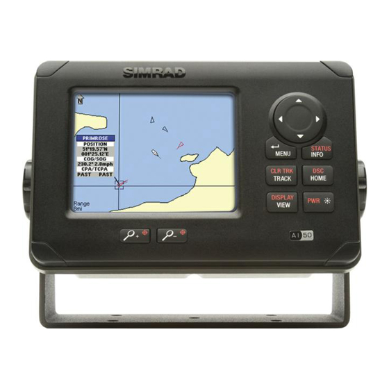
7 AIS Map Mode 7.1 General This section will describe the operational features of the AI50 Map Mode. Display Range Rings orientation Selected Target Vessels, heading & COG Own Vessel Coastline map Transmit Legend Display range Figure 7.1 – AI50 Display If the unit is returning or entering the Map mode from any other display mode, the last settings remain valid. -
Page 58: Range Rings/Info
7.3 Range rings/info The Range rings consist of three concentric circles situated around the centre point of the display. The screen range information is shown in the bottom left hand corner of the display, as shown in Figure 7.1; this indicates the range across the whole display. -
Page 59: Point Of View
7.4 Point of view The AI50 can display information in one of three ways; “NORTH UP”, “HEAD UP” and “COG UP”. The symbol in the top left corner of the display informs you of your current view. HDG UP will only be available if a compass source is present. Pressing the DISPLAY/VIEW key, will cycle through the DISPLAY DISPLAY... -
Page 60: Cursor
When the coastline detail is turned off the display will turn a light shade of green which should not be confused with land mass. Figure 7.3a - Coastline Figure 7.3b - Coastline detail on detail off 7.6 Cursor The cursor is the intersecting horizontal and vertical lines on the display, which appear whenever the 8-way NavPad is used. -
Page 61: Own Vessel
Own vessel Press and hold the INFO/STATUS key for 2 seconds, the display changes to show your own vessels information in STATUS STATUS INFO INFO a panel on the right side of the screen. Heading Own vessel data source heading or COG if no compass available Lat/Long... -
Page 62: Other Vessel (Full List)
Other vessel (full list) Press the INFO/STATUS key a second time and you can view a full listing of the information relating to that vessel. STATUS STATUS INFO INFO Figure 7.6 – Full List To enter this vessel into your “ Favorites List” simply select it. To initiate a call to this vessel using a suitable DSC VHF Radio (If attached), press and hold the HOME/DSC key. -
Page 63: Features For Vessel Information
7.9 Features for vessel information As icons with dialogue boxes move across the display, they may overlap each other; if this is the case the current highlighted selected dialogue box will be the top one. If a lost vessel icon is selected, the only information displayed in the box will be the vessels MMSI, name and last received position. -
Page 64: Text Mode
7.11 Text mode To enter Text Display Mode, from the Map view, press and DISPLAY DISPLAY hold the VIEW/DISPLAY key. The screen will change to VIEW VIEW show a list of vessels within your VHF range. Figure 7.8 – Text Mode At the top just under the title bar, are the Data Headings these are: MMSI/NAME... -
Page 65: Changing The Sort Order
Changing the sort order To change the display order in which the vessels are DISPLAY DISPLAY sorted, press the VIEW/DISPLAY key, this will cycle VIEW VIEW through the following sort order: Sort by Acquire Time • Sort by Distance (Closest first) •... -
Page 66: Tracking Your Own Vessel
To cancel individual tracking, select the vessel icon you wish to cancel and press the TRACK/CLR TRK key. The vessel icon will return to its non-bold state and the existing trail will be cleared. 7.14 Tracking your own vessel To turn own vessel tracking on, place the cursor over your CLR TRK CLR TRK vessel to highlight it and press the TRACK/CLR TRK key... -
Page 67: Light Adjustment (Short Cut)
7.16 Light adjustment (short cut) Single presses of the POWER key will cycle through the preset lighting levels, in 20% steps, for both the keypad and display. When changing light levels in this mode, the keypad light will only go to a minimum of 10%. This is to allow for viewing at night. - Page 68 Press ENTER/MENU within 2 seconds to unlock the keypad. The screen will revert back to its previous display, and the icon will disappear from the screen. The “lock” and “Unlock” messages will only remain on screen for a few seconds. 68 Display Mode...
-
Page 69: Alarms
8 Alarms 8.1 General This section details the types of visual alarms, alerts and warnings used by the AI50. All alarm windows will have a hazard symbol displayed in the title bar. All alarms relating to another vessel will display the following information about that vessel when triggered: MMSI •... -
Page 70: Collision Avoidance Alarms
8.2 Collision avoidance alarms The Simrad AI50 boasts a sophisticated, very simple to use, collision avoidance alarm system. Which, when enabled, becomes an important aid in the prevention of collisions at sea and ensures even greater safety for your vessel and passengers. - Page 71 Figure 8.1 – CPA/TCPA Alarm Because this information is live, it is continuously being recalculated and updated. To confirm and clear this alarm, press , this will close the window and return you to current display. The icon of the vessel which caused the alarm to activate will turn red, indicating an alarm condition still exists.
-
Page 72: Lost Vessel Alarm
Lost vessel alarm (1) This is a Level 1 alarm and will sound whether the Lost Vessel alarm, as described in Section 6.5, has been set by the user or not. If a vessel activates a CPA/TCPA or Guard Zone alarm, and the AIS transmissions from that vessel are lost;... -
Page 73: Biit Alarm
Figure 8.3 – Guard Zone Warning To confirm and clear this alarm press ENTER/MENU. The icon of the vessel which caused the alarm to activate will turn red, indicating an alarm condition still exists. Once a vessel leaves the Guard Zone its icon will return to the normal state. -
Page 74: Favorites Alarm
The icon of the vessel which caused the alarm to activate will change to a “Lost Vessel” icon. Refer to section 7.2. If the text display is active, the text line for that vessel’s data will be greyed out. If reception from the lost vessel’s AIS is re-established, then the icon will return to its previous state. -
Page 75: Safety Message Alarm
If the original compass unit returns to the network this will automatically be re-selected, and a message window will appear to indicate this. To confirm and clear this alarm, press , this will close the window and return you to current display. 8.7 Safety message alarm AIS technology incorporates a messaging system that allows approved users to broadcast safety messages that... - Page 76 Blank page 76 Alarms...
-
Page 77: Appendix
9 Appendix 9.1 Maintenance Periodically wipe down the casing and display screen with a clean damp cloth. To remove heavier marks use mild soapy water, dampen cloth and wring out thoroughly before wiping unit. Never use cleaning solutions containing spirit or alcohol as these can damage the unit. -
Page 78: Accessories
9.3 Accessories The following accessories are available from local Simrad agents: VA14* VHF AIS antenna - S/S whip with 20 metres Cable, terminated in a PL259 plug. * One off required for operation 9.4 Product specifi cations AIS Type Class B for use on non-SOLAS craft VHF Receiver Receiver type Dual TDMA (shared DSC) - Page 79 SimNet/NMEA2000 PGN’s NMEA2000 Mandatory PGNs 59392 ISO Acknowledgment 59904 ISO Request 60928 ISO Address Claim 126996 NMEA2000 Product Information NMEA2000 Data PGNs 126992 System Time 129025 Position, “Rapid Update” 129026 COG & SOG, “Rapid Update” NMEA2000 AIS PGNs 129038 Class A Position Report 129039 AClass B Position Report 129040...
-
Page 80: Dimensions
9.5 Dimensions Figure 9.1 - AI50 dimensions Figure 9.2 - GPS Antenna dimensions 9.6 Service and warranty If it is necessary to have a unit repaired, please contact your local authorized dealer. For worldwide warranty details and a list of authorised Simrad agents please refer to the Warranty Card supplied with this unit. -
Page 81: Declaration Of Conformity (Eu)
9.7 Declaration of Conformity (EU) English Hereby, Simrad Limited (Margate) declares that this AI50 is in compliance with the essential requirements and other relevant provisions of Directive 1999/5/ Finnish Simrad Limited (Margate) vakuuttaa täten että AI50 tyyppinen laite on direktiivin 1999/5/EY oleellisten vaatimusten ja sitä... - Page 82 Blank page 82 Appendix...
-
Page 83: Index
10 Index 8-way NavPad 22, 25 display nomenclature 55 display offset 36 DSC call 61, 63 DSC Radio 54 accessories 76 alarm priority 67 alarms BIIT 71 ENTER/MENU 23, 25 CPA/TCPA 42, 68 favorite 45, 72 guard zone 44, 70 favorites list loss of compass heading data 72 add to 39, 60... - Page 84 TRACK/CLR TRK 23, 63, 64 tracking language 48 clear all tracks 64 light adjustment 65 clear tracks 63 lost vessel persistence 45 individual vessels 63 own vessel 64 tracking offset 36 transmit enable/disable 50 MMSI 30, 75 transmit legend 58 modes of operation troubleshooting 75 text mode 62...
Need help?
Do you have a question about the SIMRAD AI50 and is the answer not in the manual?
Questions and answers