Table of Contents
Advertisement
Advertisement
Table of Contents

Related Manuals for IP-COM G3210P


Summary of Contents for IP-COM G3210P
-
Page 2: Disclaimer
Copyright of the whole product as integration, including its accessories and software, belongs to IP-COM Networks Co., Ltd. No part of this publication can be reproduced, transmitted, transcribed, stored in a retrieval system, or translated into any language in any form or by any means without the prior written permission of IP-COM Networks Co., Ltd. -
Page 3: Preface
Preface Preface Thank you for choosing IP-COM! Reading this manual will be helpful for you to configure this device. Convention If not specifically indicated, the switch, this product, or this device mentioned in this Install Guide stands for IP-COM 8GE+2SFP Managed PoE Switch G3210P. -
Page 4: Table Of Contents
Contents Contents Copyright Statement ........................i Disclaimer ............................i Preface ............................. ii Convention............................ii Overview of this Install Guide ......................ii Technical Support ..........................ii Contents ............................iii Product Overview .......................... 1 Package Contents ..........................2 Physical Appearance ........................2 Installation ............................ -
Page 5: Contents
Contents QoS ..............................97 Security ............................108 Maintenance ........................... 113 Logout ............................. 119 Save Configurations ........................121 Appendix ............................. 124 FAQs ..............................125 Technical Specifications ....................... 125 Default Settings ..........................129 Safety and Emission Statement ....................133... -
Page 6: Product Overview
Product Overview Package Contents Physical Appearance... -
Page 7: Package Contents
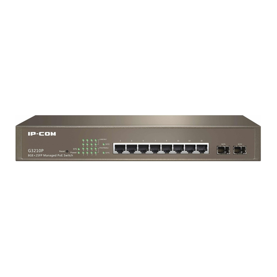
Product Overview Package Contents Open the package and verify the following items: Switch (1) Power Cord (1) L-shaped Bracket (2) Screw (6) Footpad (4) Install Guide (1) If any item is missing or damaged, contact the place of purchase immediately. Physical Appearance 1 Front Panel The following parts are located on the front panel shown as below. - Page 8 Product Overview Solid A valid link is established on the corresponding RJ45 port. Data transmission is occurring on the corresponding RJ45 Link/Act Blinking port. No link is established on the corresponding RJ45 port. The PoE powered device (PD) is connected on the Solid corresponding RJ45 port and the port is supplying power PoE/Status...
-
Page 9: Back Panel
G3210P only supports LC optical fiber connector as shown below: Tip: The optical fiber module or photoelectric converter is not included in the package and you need to prepare it by yourself. - Page 10 Product Overview for the method of connecting protective grounding cable, please refer to Connect to Protective Grounding Cable. Power Socket Used for connecting the included power cord for power supply.
-
Page 11: Installation
Installation Installation Considerations Tools Installation Connect to Protective Grounding Cable Connect to Power Supply Cable Connection Power Up the Device... -
Page 12: Installation Considerations
Note: There is an IP-COM seal on one of the screws. You should keep the seal unbroken before the technical staff maintains your switch. You should not open the housing of the device unless you get the local reseller’s permission, or you have the technical capabilities and... -
Page 13: Tools
Installation 3.Inductive Lightning Protection In case a strong current does damage to the switch due to inductive lightning, verify that: Power socket, rack, work bench and the grounding terminal of the switch are well-grounded The switch is cabled properly. When the switch is cabled outdoors, it is advisable to ... - Page 14 Installation Step 3: Insert screws through each bracket and into the rack to securely fix the switch onto the rack. B. Mount the switch on a desktop Without a 19-inch standard rack you can install the switch on a desktop. Step 1: Place the switch bottom up on a flat desktop Step 2: Attach four footpads to the corresponding circular grooves on the bottom of the switch...
-
Page 15: Connect To Protective Grounding Cable
Installation Step 3: Place the switch face up on the desktop. 4 Connect to Protective Grounding Cable Proper connection of protective grounding cable is not only important for inductive lightning protection and anti-interference, but for your own personal safety. Please select the most suitable method to connect protective grounding cable according to your installation environment. -
Page 16: Connect To Power Supply
Installation Step 1: Bury an angle iron or steel pipe (≥0.5m) into the ground; Step 2: Weld one end of the protective grounding cable to the angle iron or steel pipe and embalm the welding point; Step 3: Connect the other end of the protective grounding cable to the grounding terminal. If not allowed to bury the grounding bar, you can connect it to ground through the three-core PE cable of the AC power socket on the precondition that the PE cable in the switchgear room, or beside the AC power supply transformer, is well-grounded. - Page 17 Installation Connect the switch to remote Ethernet devices with Ethernet cables. Tip: All RJ45 ports of the switch are Auto MDI/MDIX-capable, which allows you to attach devices using twisted-pair Category 5 (or higher), either straight-through or crossover, cables. Connect to SFP Fiber Ports Step 1: Insert the SFP module into the SFP module bay.
- Page 18 Installation Connect to PDs The PoE power supply feature on all RJ45 ports is enabled by default. You can connect IEEE 802.3at-/802.3af-compliant APs, IP telephones, IP cameras or other powered devices to the switch.
-
Page 19: Power Up The Device
Installation Tip: The PoE power supply mode is dynamic, i.e. the switch accommodates power supply for powered devices automatically. 7 Power up the Device Check the device thoroughly before powering up the device. 7.1 Check the Device Before applying power supply, perform the following: The operating power supply should accord with rated input standard ... -
Page 20: Device Management Introduction
Device Management Introduction Web Administration Web Login Web Logout Layout of Web Browser-Accessible Administrator Page Commonly Used Elements on Web Browser-Accessible Administrator Page... -
Page 21: Web Administration
Device Management Introduction 1 Web Administration This switch comes with the web administration feature, which helps you manage and maintain this switch intuitively via its web browser-accessible administrator page. The network topology of application scenario is shown below: 2 Web Login The first time you use this device, you can log in to its web browser-accessible administrator page with following default login info. - Page 22 Device Management Introduction 3. Launch a web browser, input 192.168.0.1 in the address bar and press Enter. 4. Enter the default user name admin and default password admin, and click Login. 5. Go to the web browser-accessible administrator page to view or modify the switch’s configuration info.
-
Page 23: Web Logout
Device Management Introduction 3 Web Logout Directly closing your web browser or clicking Logout exits the web browser-accessible administrator page. Configurations won’t be saved automatically while logging out. It is advisable to save your configurations manually before logout. Note: Closing the web browser tab won’t log out automatically. -
Page 24: Commonly Used Elements On Web Browser-Accessible Administrator Page
Device Management Introduction Sequence Name Description Number ❶ The navigation bar presents web administration Navigation functions to you in the form of navigation tree. This section allows you to select function menus here. ❷ Configuration This section allows you to configure and view Section settings here. - Page 25 Device Management Introduction Used for canceling your settings on the current page and to go back to the previous page. Used for deleting all rules on the page. Used for deleting selected rules on the page. Used for looking up rules which match the search criteria. Used for clearing all statistics on the current page.
-
Page 26: Advanced Settings
Device Management Introduction Advanced Settings Administration Port Management VLAN Management PoE Management Time Range Management Device Management Security Maintenance Logout Save Configurations... -
Page 27: Administration
Advanced Settings Administration This section helps you view and configure basic info for the switch and instructs you how to use system maintenance tools. Specifically, the following two parts are included: System Configuration: This section describes how to configure switch system info/time, reboot the switch, reset the switch and upgrade the software version of the switch. - Page 28 Advanced Settings Firmware Version Display the switch’s software version and release date. Hardware Display the switch’s hardware version. Version MAC Address Display the switch’s physical address. Management 802.1Q VLAN ID of the switch (default: 1). If you want to change the management VLAN, click VLAN Management >...
-
Page 29: System Time
Advanced Settings Aging time of the switch’s dynamic MAC address (10~1000000s). The default value is 300s. When it is set to 0, MAC address won’t be aged. MAC Age Tip: This switch maintains an independent MAC address (forwarding) table for each VLAN. 1.2 System Time This page displays and allows you to configure system time for the switch. - Page 30 Advanced Settings Configuration steps for acquiring system time via SNTP server: 1. Select a time zone from the Time Zone drop-down list; 2. Select Server Setup; 3. Enter proper SNTP server IP addresses in the Preferred / Alternate SNTP Server field;...
- Page 31 Advanced Settings 3. Set proper date and time manually; 4. Click OK. When system time is configured successfully, you can view Current Time on this page to check whether your time settings are activated or not. 1.3 Reset If you forgot your login info, like username/password or management VLAN, etc. or if you have a problem in surfing the Internet but cannot find out where the problem is, it is advisable to reset this device.
-
Page 32: Firmware Update
Advanced Settings 3. Click Reset… and then follow onscreen instructions. Tip: After resetting this device, the management VLAN of the switch will be set to 1, the default login IP address is 192.168.0.1 and the default login username and password will be admin for both. -
Page 33: System Security
Advanced Settings Upgrading Procedures: 1. Log in to our website www.wirelessnetworkproducts.com to download the latest software to your local computer; 2. Click Administration > System Configuration > Firmware Update to enter page below: 3. Click Browse to select the software file you wish to upload from your local computer;... - Page 34 Advanced Settings Parameters on this page are described below: Field Description This field specifies how long the web manager is allowed to remain idle. When reaching the set time, the web manager will return to login Login Timeout window. The Login Timeout can be set to any value between 30 and 3600 seconds.
- Page 35 Advanced Settings 4. Click OK. Once you’ve changed your password, the next time you log in to the switch remember to use the new password. If you forget the password, pressing the Reset button for over 5 seconds and releasing it will restore the device to its factory default and your login password will be the default admin.
-
Page 36: Port Management
Advanced Settings Port Management This section details packets forwarding on all ports. The following two parts are included: Port Configuration: This section allows you to configure basic properties for all ports and port mirroring. And you can also view port statistics here. Link Aggregation: This section helps you increase link bandwidth and provides redundancy backup for the switch. - Page 37 Advanced Settings Parameters on this page are described below: Field Description Display actual link rates and duplex modes on corresponding ports. Link Status "--" is displayed if a port is not linked or link failure occurs. Three types of duplex modes are available on RJ45 ports: 10M, 100M, 1000M.
- Page 38 Advanced Settings With flow control enabled on both the switch and its link partner and full duplex mode enabled on the port, when congestion occurs the port will send flow control frames to notify the link partner of such. Upon receiving such frames, the link partner will temporarily stop sending packets to the switch, thus avoiding packets drop and ensuring a reliable network.
-
Page 39: Port Mirroring
Advanced Settings it will join the same isolation group automatically. Configure sizes of Jumbo Frames the switch has received. The valid range is 1518~9216. The default value is 1518, which is the longest one in IEEE802.3 standard. Jumbo Frame Once Jumbo Frame size is configured, the system will deal with data that ports have received within the size length. -
Page 40: Port Statistics
Advanced Settings configured as a mirroring destination port. Select the mirroring source port. None indicates the corresponding port won’t be mirrored. Ingress: Only incoming packets on this port are copied to the mirroring destination port. Egress: Only outgoing packets on this port are copied to the mirroring destination port. -
Page 41: Link Aggregation
Advanced Settings To view port statistics on a certain port, click the corresponding port number. 2 Link Aggregation Link Aggregation groups multiple Ethernet ports together in parallel to act as a single logical link. Aggregation-enabled devices treat all physical links (ports) in an aggregation group entirely as a single logical link (port). - Page 42 Advanced Settings In the same aggregation group, all member ports must be set to the same configurations with respect to STP, port priority, VLAN configuration and port management. The following are illustrations in detail: Ports joining aggregation groups should share the following configurations: STP ...
- Page 43 Advanced Settings LACP Aggregation Based on IEEE 802.3ad, LACP (Link Aggregation Control Protocol) provides a method to implement link aggregation dynamically. Whether ports in LACP group are aggregation ports or not is determined by LLDPDU frame auto-negotiation. LACP is enabled on the member ports in LACP mode.
- Page 44 Advanced Settings Source & Dest Indicate member ports in a link aggregation group share traffic load according to source and destination MAC addresses. Source & Dest Indicate member ports in a link aggregation group share traffic load according to source and destination IP addresses. Procedures for adding static aggregation: 1....
- Page 45 Advanced Settings 2. On the appearing page type in a valid aggregation group number (1-2); 3. Select LACP; 4. Select ports to join the aggregation group. Up to 8 ports and down to 2 ports can be added to each; 5....
- Page 46 Advanced Settings To batch configure LACP parameters, click Configure to enter page below: Parameters on the page are described below: Field Description Configure system priority (0-65535). The default is 32768. The smaller the value is, the higher the system priority is. When data transferring among different systems, the system with higher priority System Priority can determine to which aggregation link the link belongs;...
- Page 47 Advanced Settings Configure LACP timeout. If the LACP aggregation group is not Timeout aggregated, LACPDU frames will be re-sent for auto-negotiation. The default setting is long. Group ID Display the LACP aggregation group ID.
-
Page 48: Vlan Management
Advanced Settings VLAN Management In traditional medium sharing Ethernet and switched Ethernet, all users are in a broadcast domain. With more and more PCs appearing in the networking, broadcast packets increase, which greatly increases data flow among devices in the networking. Thus, network performance becomes worse. - Page 49 Advanced Settings dispersed as they are logically related instead of physically on the same VLAN. Thus network administrators do not need to re-configure the network when a VLAN member changes its location. Better network security. PCs in different VLANs cannot intercommunicate directly. ...
- Page 50 Advanced Settings to 0 by default. VLAN ID, a 12-bit field specifying the VLAN to which the frame belongs. The VLAN ID range is 0 to 4095. Usually, 0 and 4095 are reserved, so a VLAN ID actually ranges from 1 to 4094. ...
- Page 51 Advanced Settings If the VID value of the packet belongs to Tagged VLAN, the packet will be forwarded with Tag; If Hybrid the VID value of the packet belongs to Untagged VLAN, the packet will be forwarded after removing its VLAN tag.
- Page 52 Advanced Settings Add 802.1Q VLAN: 1. Click New; 2. Type in the VLAN ID; 3. Select ports which belong to the VLAN ID; 4. Click OK. Tip: Up to 20 characters are allowed for VLAN ID. When multiple values are entered, ...
- Page 53 Advanced Settings By default, all ports belong to 802.1Q VLAN1. If a VLAN ID is deleted, ports included in this VLAN will belong to 802.1Q VLAN1 automatically. Up to 64 802.1Q VLANs can be configured. 1.3 Trunk Port In 802.1Q VLAN mode, port link type is Access by default.
- Page 54 Advanced Settings Edit Trunk ports: To modify some parameters of Trunk ports, such as PVID, VLAN, see steps below: 1. Click the corresponding Trunk port number on the Trunk Port page; 2. Modify parameters on the appearing page; Delete Trunk ports: Firstly, click VLAN Management >...
- Page 55 Advanced Settings Click Delete behind the corresponding port number. To batch delete Trunk ports, check ports you wish to delete and click Batch Delete. Tip: A port cannot be configured to be the Hybrid port and Trunk port at the same time. If ...
-
Page 56: Port Vlan
Advanced Settings 6. Click OK. 2 Port VLAN Port VLAN may be the easiest and most effective solution for partitioning VLAN. Users in the same VLAN can intercommunicate with each other and the same user can belong to multiple VLANs. For example, if port 1 and port 2 join a VLAN, and port 1 and port 3 join another VLAN, all data on port 2 and port 3 will only be forwarded to port 1. - Page 57 Advanced Settings 2.1 VLAN Mode Toggle To set VLAN mode to Port VLAN, click VLAN Management > VLAN Configuration > VLAN Mode Toggle to enter page below: 2.2 Port VLAN To create port VLANs, click VLAN Management > VLAN Configuration > Port VLAN to enter page below: Add Port VLAN: 1....
- Page 58 Advanced Settings 4. Click OK; Edit port VLAN: Click the corresponding port VLAN to enter the corresponding page to edit it. As mentioned above, Port 2 and port 3 are in VLAN1. If you want to isolate port 2, 3 from other ports, just delete port 2 and port 3 from VLAN1.
-
Page 59: Voice Vlan
Advanced Settings Tip: Up to 10 port VLANs can be configured. Port VLAN cannot achieve inter-switch communication. Only ports that belong to the same VLAN on the same switch can intercommunicate. 3 Voice VLAN With the development of voice technology, voice devices are becoming more and more widely used, especially in broadband resident districts. - Page 60 Advanced Settings Manual: In this mode, you need to add the port connected to the IP telephone into voice VLAN manually. Then the system will try to match OUI addresses by recognizing source MACs of packets. If matched successfully, the system will issue ACL rules and configure priority for these packets.
- Page 61 Advanced Settings Untagged Access, Trunk, Hybrid: Not supported. Access: Not supported. Trunk: Supported, but the default VLAN of the access port must already exist and can’t be voice VLAN. And the default VLAN is allowed on the Tagged access port. Hybrid: Supported, but the default VLAN of the access port must already exist and can’t be voice VLAN.
-
Page 62: Global Setup
Advanced Settings default VLAN is allowed on the access port. Supported, but the default VLAN of the access port must already exist and can’t be voice VLAN. And Hybrid voice VLAN should be in the allowed tagged VLAN list. ... -
Page 63: Port Setup
Advanced Settings Parameters on the page are described below: Field Description Configure how ports forward messages. Voice VLAN Security Disable: All messages will be forwarded. Enable: Only voice Mode traffic will be forwarded. As for the port joining voice VLAN under auto mode, if the system doesn't receive any voice message after ageing time, Voice VLAN Aging this port will be removed from voice VLAN automatically. - Page 64 Advanced Settings To batch configure voice VLAN settings, click Config on the Port Setup page. Parameters on the page are described below: Field Description Port Display port number. Voice VLAN Port Select voice VLAN working mode: Auto or Manual. If it is Manual, Mode age time of voice VLAN becomes invalid.
- Page 65 Advanced Settings By default, recognizable OUI addresses of this switch are described as below: OUI Address OUI Mask Description 0001-E300-0000 FFFF-FF00-0000 Siemens 0003-6B00-0000 FFFF-FF00-0000 Cisco 0004-0D00-0000 FFFF-FF00-0000 Avaya 0060-B900-0000 FFFF-FF00-0000 Philips/NEC 00D0-1E00-0000 FFFF-FF00-0000 Pingtel 00E0-7500-0000 FFFF-FF00-0000 Polycom 00E0-BB00-0000 FFFF-FF00-0000 3com You can also click Add on the OUI Setup page to add OUI addresses manually.
- Page 66 Advanced Settings Select the corresponding OUI mask from the drop-down list. The default is FFFF-FF00-0000, indicating only the top 24 bits must Mask match the OUI address, can it be recognized as voice stream and the last 24 bits are arbitrary. Description of the corresponding manufacturer for a certain OUI Description address or other info.
-
Page 67: Poe Management
Advanced Settings PoE Management In traditional networking, all terminal devices are applying power supply directly via power lines, leading to high expenses and complicated cabling work. Power over Ethernet or PoE describes any of several standardized or ad-hoc systems which pass electrical power along with data on Ethernet cabling. - Page 68 Advanced Settings Parameters on this page are described below: Field Description Enable/Disable PoE feature. Only PoE feature is enabled on the port, Enable PoE can PoE function takes effect. Transmission Display PoE power on the corresponding port. The unit is W. Note Power that there may be errors on values displayed on the page.
-
Page 69: Time Range Management
Advanced Settings Time Range Management Time range is used for describing a special time range, via which you can customize this switch’s PoE power supply time range, achieving smart power management and saving resources. Click Time Range Management to enter page below: Parameters on this page are described below: Field Description... - Page 70 Advanced Settings 6. Click OK to save your settings. Edit time range: If you want to modify a certain time range, click the corresponding time range ID to enter similar page below:...
-
Page 71: Device Management
Advanced Settings Device Management This section helps you enhance the switch’s traffic forwarding capacity and manage the switch efficiently. The following five parts are included: MAC: Manage this switch’s MAC address forwarding table. STP: Eliminate physical loop in data link layer, avoid broadcast storm and provide link backup redundancy. - Page 72 Advanced Settings Static MAC entries, also known as "Permanent Address", which are manually added and never age out. For a small network with little change, adding static MAC address entry manually may effectively reduce broadcast traffic. Dynamic MAC entries, which can be manually added or dynamically learned and ...
-
Page 73: Static Mac Address
Advanced Settings Click this button to bind corresponding MAC address to a specific port. And the same button changes to Bound after being clicked. View MAC address entry: Click View and specify a MAC and a VLAN ID to view MAC address entries. To view MAC address entry, you must enter the MAC address while the VLAN ID is optional. - Page 74 Advanced Settings Tip: Each VLAN has a corresponding MAC address table. The same MAC address can be added into different VLANs. The MAC address entry in the Static Address Table cannot be added to the Filtering Address Table. Once VLAN mode is toggled, all current settings will be cleared.
- Page 75 Advanced Settings the bridge priority is a configurable parameter. The smaller the bridge ID is, the higher the bridge priority is. The root bridge is the bridge with the lowest bridge ID. 2.Root Bridge There is only one root bridge in the networking and it is changeable as the network topology changes.
- Page 76 Advanced Settings BPDU Comparison Each switch sends out configuration BPDUs and receives a configuration BPDU on one of its ports from another switch. The following table shows the comparing operations. Step Operation If the priority of the BPDU received on the port is lower than that of the BPDU if of the port itself, the switch discards the BPDU and does not change the BPDU of the port.
- Page 77 Advanced Settings resulting BPDU; If the BPDU of this port takes the precedence over the resulting BPDU, the BPDU of this port is not replaced and the port is blocked. The port only can receive BPDUs. Tip: In a STP with stable topology, only the root port and designated port can forward data, and the other ports are blocked.
- Page 78 Advanced Settings connecting to a point-to-point link, it can transit to forwarding state after getting response from the downstream switch through handshake. RSTP Elements 1.Edge Port The edge port is a configurable designation port that is directly connected to a segment where a loop cannot be created.
- Page 79 Advanced Settings Parameters on this page are described below: Field Description Enable/Disable STP feature on this device. STP Status By default, the STP feature is disabled. Select the desired version of STP version. STP Version STP: Spanning-tree-compliant mode. RSTP:Rapid-spanning-tree-compliant mode. Select a BPDU processing method when STP is disabled on this device.
- Page 80 Advanced Settings To configure STP parameters on a single port, click the corresponding port number. To batch configure STP parameters, click Config.
- Page 81 Advanced Settings Parameters on this page are described below: Field Description Enable/Disable STP feature on ports. STP Status By default, the STP feature is disabled. Enabling global and port STP feature makes port STP feature effective. Configure port priority, which is an important for selecting root port. Under the same conditions, the port with higher priority will be selected Priority as the root port.
- Page 82 Advanced Settings 3 IGSP IGMP Snooping (Internet Group Management Protocol Snooping) is a multicast constraint mechanism on layer 2 switches for managing and controlling multicast groups. Principle of IGMP snooping By analyzing IGMP packets, the IGMP-Snooping-enabled layer-2 device will establish a map of links for ports and multicast MAC addresses, and forward multicast data.
- Page 83 Advanced Settings How IGMP Snooping Works A switch that runs IGMP snooping performs different actions when receiving different IGMP messages. 1.Group query The IGMP querier periodically sends IGMP general queries to all hosts and routers on the local subnet to query which multicast group members exist on the subnet. After receiving an IGMP general query, the switch forwards it through all ports in the VLAN (except the port that receives the query) and performs corresponding actions on the receiving port (mainly resets/enables the age timer on this port).
-
Page 84: Igmp Snooping
Advanced Settings group-specific query before the aging timer expires, it indicates there are still multicast group members of this port and the switch will reset the aging timer on the port. If the port receives no IGMP membership report in response to the group-specific query before its aging timer expires, it indicates there are no multicast group members of this port and the switch will remove the multicast forwarding entry that the port corresponds to from the forwarding table when the aging timer expires. -
Page 85: Fast Leave
Advanced Settings invalid. The default is 260s. Range: 200~1000s. Enable/Disable the Unknown Multicast Drop feature. If enabled, the switch will drop unknown multicast packets it has received; If disabled, the switch will broadcast unknown multicast packets it has received. Unknown Multicast Drop Tip:... - Page 86 Advanced Settings To batch configure such settings, click Config to enter page below: 4 SNMP Simple Network Management Protocol (SNMP), the most widely used network management protocol in TCP/IP networking, is an OSI Layer 7 (Application Layer) designed specifically for managing and monitoring network devices. SNMP enables network management stations to read and modify the settings of gateways, routers, switches, and other network devices.
- Page 87 Advanced Settings SNMP agent: Software which runs on managed devices for maintaining management information base and reporting management data to a SNMP management system when it is needed. MIB: A management information base (MIB) is a database used for managing the ...
- Page 88 Advanced Settings access of the illegal user by authenticating the senders of packets. Meanwhile, the encryption function is used to encrypt the packets transmitted between SNMP Manager and SNMP Agent so as to prevent any information being stolen. The multiple combinations of authentication function and encryption function can guarantee a more reliable communication between SNMP Management station and SNMP Agent.
- Page 89 Advanced Settings Click Device Management > SNMP > User to Create SNMP Required create SNMPv3 users, configure user option authentication and encryption settings for users. Click Device Management > SNMP > Enable Configure Required Trap to enable the Trap function, click Device SNMP Trap option Management >...
- Page 90 Configure contact info for the switch so that the SNMP manager can quickly locate the switch. Usually, it includes the domain name and IP address of the switch. The default contact info is www.ip-com.com.cn. Physical Configure physical location info for the switch so that the SNMP Location manager can quickly locate the switch.
- Page 91 Advanced Settings community name should be within 31 characters. Access Mode Define the access rights of the community. Read only: Management right of the Community is restricted to read-only, and changes cannot be made to the corresponding View. Read & write: Management right of the Community is read-write and changes can be made to the corresponding View.
- Page 92 Advanced Settings Parameters on this page are described below: Field Description User Name Enter the user name here. Select the group name here. You need to go to the Device Management > SNMP > Group page to configure group settings Group Name first.
- Page 93 Advanced Settings Click Add to enter page below. Note that you must create a view before you can add a group. Parameters on this page are described below: Field Description Enter the SNMP Group name. The Group Name and Security Level Group Name compose the identifier of the SNMP Group.
- Page 94 Advanced Settings 4.4 View The OID (Object Identifier) of the SNMP packets is used to describe the managed objects of the switch, and the MIB (Management Information Base) is the set of the OIDs. The SNMP View is created for the SNMP manager to manage MIB objects. Click Device Management >...
- Page 95 Advanced Settings 4.5 Enable Trap Trap function is used to inform the SNMP manager of critical events for the switch. Click Device Management > SNMP > Enable Trap to enter page below: By default, the SNMP Trap function is enabled on all ports. You can modify it as you need. Parameters on this page are described below: Field Description...
-
Page 96: Dhcp Snooping
Advanced Settings Click Add to enter page below: Parameters on this page are described below: Field Description Enter an IP address for the destination host. Note that the host IP Destination should be on the same IP net segment as the management IP of the Host IP switch. - Page 97 Advanced Settings security of an existing DHCP infrastructure. When DHCP servers are allocating IP addresses to the clients on the LAN, DHCP snooping can be configured on LAN switches to harden the security on the LAN to allow only clients with specific IP/MAC addresses to have access to the network.
- Page 98 Advanced Settings Use the default circuit ID sub-option and remote ID sub-option on this switch to fill Disable Option 82. Then the previous Option 82 information will be replaced and forwarded. The previous Option 82 information will be Keep kept and forwarded.
- Page 99 Advanced Settings Enable/Disable source MAC address check-up function. There are Source MAC two fields in DHCP packets for storing client MAC addresses. Once Address this function is enabled, the switch will make a comparison between Check-up these two fields. If these two fields are different, packets will be dropped.
- Page 100 Advanced Settings Parameters on pages are described below: Field Description Display the corresponding port number. Port Configure the current port's DHCP snooping property: trust or Port Properties untrust. Enable/Disable option 82. Option 82 records DHCP clients' location Option 82 Status info.
- Page 101 Advanced Settings Parameters on this page are described below: Field Description Display user binding digits in the list. IP Address Display the user binding's IP address. MAC Address Display user binding's MAC address. VLAN Display user binding's VLAN ID. Port Display user binding's port number.
-
Page 102: Qos
Advanced Settings QoS (Quality of Service) functions to provide different quality of service for various network applications and requirements and optimize the bandwidth resource distribution so as to provide a network service experience of a better quality. The following two parts are included: Configuration: Provide different network applications with different quality of service. - Page 103 Advanced Settings Packets classification: Identifies packets conforming to certain characters according to certain rules. Map: The user can map the ingress packets to different priority queues based on the priority modes. Queue scheduling algorithm: When the network is congested, the problem that many ...
- Page 104 Advanced Settings By default, the 802.1P priority tags are mapped to the Switch’s priority queues as follows: 802.1p Priority Queue 2.DSCP Priority As shown in the figure above, the ToS (Type of Service) in an IP header contains 8 bits. The first three bits indicate IP precedence in the range of 0 to 7.
- Page 105 Advanced Settings When congestion occurs on the network, the problem that many packets compete for resources must be solved, usually in the way of queue scheduling. The switch provides two schedule modes: SP(Strict-Priority)and WRR (Weighted Round Robin). 1.Strict Priority Mode Strict Priority Queueing is specially designed to meet the demands of critical services or applications.
- Page 106 Advanced Settings WRR-Mode: Weight Round Robin Mode. In this mode, packets in all the queues are sent in order based on the weight value for each queue and every queue can be assured of a certain service time. Assuming there are 4 egress queues on the port. The four weight values (namely, w4, w3, w2, and w1) indicate the proportion of resources assigned to the four queues respectively.
- Page 107 Advanced Settings Parameters on this page are described below: Field Description Select scheduling mode for the switch: SP or WRR. SP: Strict-Priority Mode. In this mode, the queue with higher priority Scheduling will occupy the whole bandwidth. Packets in the queue with lower Scheme priority are sent only when the queue with higher priority is empty.
-
Page 108: Port Priority
Advanced Settings queues according to mapping relations you’ve set. 1.3 DSCP On this page you can configure DSCP priority. DSCP (DiffServ Code Point) is a new definition to IP ToS field given by IEEE. This field is used to divide IP datagram into 64 priorities. -
Page 109: Traffic Control
Advanced Settings By default, CoS priority on all ports is 0 and you can modify it as you need. 2 Traffic Control The Traffic control function, limiting bandwidth and broadcast traffic on each port, is implemented on the Bandwidth Control and Storm Constrain pages. 2.1 Bandwidth Control This switch adopts token bucket for flow control. - Page 110 Advanced Settings By default, no bandwidth control settings are configured on all ports. You can click the corresponding port number or click Config on the Bandwidth Control page to configure bandwidth control settings. Parameters on this page are described below: Field Description Ingress...
- Page 111 Advanced Settings To configure storm constrain settings on a single port, click the corresponding port number. To batch configure storm constrain settings, click Config. Parameters on this page are described below: Field Description Enable/Disable constrain function of the broadcast Broadcast Packet Constrain packet (its destination MAC is FF: FF: FF: FF: FF: FF)
- Page 112 Advanced Settings on the corresponding port. Once this function is enabled, you need to specify a broadcast constrain value within a range of 128~50000kbps. Enable/Disable constrain function of the multicast packet (the 8 bit of its destination MAC is 1) on the Multicast Packet Constrain corresponding port.
-
Page 113: Security
Advanced Settings Security This section provides your local area network with security assurance. The following two parts are included: Filter: Manage Internet access for computers in local area network. 802.1X: Authenticate access users in LAN and ensure security for LAN devices and resources. - Page 114 Advanced Settings Tip: The MAC address in the Static Address Table cannot be added to the Filtering Address Table. This MAC address filtering function is not available if the 802.1X feature is enabled. 2 802.1X IEEE 802.1X is an IEEE Standard for port-based Network Access Control (PNAC). It is part of the IEEE 802.1 group of networking protocols.
- Page 115 Advanced Settings Client: A client device (such as a laptop) that wishes to attach to the LAN/WLAN for authentication should support EAPOL (Extensible Authentication Protocol over LAN) . Device: It is a network device, such as an Ethernet switch or wireless access point. ...
- Page 116 Advanced Settings Parameters on this page are described below: Field Description Enable/Disable 802.1X feature globally. By default, the 802.1X feature is disabled globally on the device. Global Mode Tip: 802.1X settings take effect only when the 802.1X feature is enabled on both the device and designated ports.
-
Page 117: X Port Statistics
Advanced Settings To batch configure 802.1X port settings, click Config to enter page below: Parameters on this page are described below: Field Description Mode Select to enable /disable 802.1X function. Select the 802.1X port control mode from the drop-down list. Auto: Initially, the port is unauthorized. -
Page 118: Maintenance
Advanced Settings Maintenance This section helps you know about operation status of this switch and provides you with methods of network diagnostics. Syslog: View system logs, monitor network operation and troubleshoot network malfunction if necessary. Network Diagnostics: When malfunction occurs, detect it via cable/Ping/tracert test. 1 Syslog As the system information hub, system logs record, classify and manage system information, which offers a powerful support for network administrators to monitor network... - Page 119 Advanced Settings 1.1 Logs To view and download system logs, click Maintenance > Syslog > Logs to enter page below: For real-time network monitoring and network malfunction diagnosis, it is advisable to click Administration > System Configuration > System Time to configure system time for your switch so that the system can obtain correct system time.
-
Page 120: Network Diagnostics
Advanced Settings Parameters on this page are described below: Field Description Enable Logging Check it to enable syslog feature. It is enabled by default. Check it to enable the server for remote logging. It is disabled by Enable Server default. - Page 121 Advanced Settings 2.1 Cable Check-up On this device, you can test current cabling situations on all Ethernet interfaces, pair A, B, C, D connection status and pair length included. Click Maintenance > Network Diagnostics > Cable Check-up to enter page below: Tip: The pair length is the total length of the twisted cable, not the length of its cable skin.
- Page 122 Advanced Settings 2.2 Ping Check-up Ping is a computer network administration utility used to test the reachability of a host on an Internet Protocol (IP) network and to measure the round-trip time for messages sent from the originating host to a destination computer. Ping test process and principles: 1....
- Page 123 Advanced Settings Message Configure ICMP request packets length (18~512 bytes). By default it Sending is 56 bytes. Length Configure ICMP request packets time interval (100~1000ms). The Time Interval default is 100ms. Ping Result Display the ping result. 2.3 Tracert Check-up Tracert is a computer network diagnostic tool for displaying the route (path) and measuring whether network connection is available or not.
-
Page 124: Logout
Advanced Settings Tracert Test: 1. Click Maintenance > Network Diagnostics > Tracert Check-up; 2. Specify parameters in corresponding fields and click OK; Parameters on this page are described below: Field Description Destination IP Specify the destination host IP address for tracert test. Address Specify the maximum number of routers the test data can pass Hop-count... - Page 125 Advanced Settings You can also close the web browser directly to log out safely. Note: Closing the web browser tab won’t log out automatically.
-
Page 126: Save Configurations
Advanced Settings Save Configurations Click Save Configurations to enter page below to manage this switch’s configuration info. Save Current Settings If you want to save your settings after reboot, click Save on this page. Note: Operations, like power up the switch after disconnect its power supply, reset the switch, upgrade the switch, etc. - Page 127 Advanced Settings 2. Click Save on the pop-out dialog; 3. Select a path to save files to your local PC and click Save.
- Page 128 Advanced Settings Tip: By default, the file name is “mib.conf”. To make it remembered easily, you can modify the file name “mib”, but do not modify the file extension “.conf”. Restore Previous Settings If you want to configure the same settings for multiple switches, or if you carelessly perform some actions, leading to performance degradation, you can use this function to restore previous settings for this switch.
-
Page 129: Appendix
Appendix Technical Specifications Default Settings Safety and Emission Statement... -
Page 130: Faqs
Appendix FAQs 1.Power supply troubleshooting You can know whether the power supply is working fine or not according to the status of Power LED. If the power supply is working fine, the Power LED is solid; if the Power LED is off, please verify that: The power cord is correctly connected and the power switch is on;... - Page 131 Appendix Operating Storage 10% ~ 90% RH (non-condensing) | 5% ~ 90% RH Humidity (non-condensing) UL 60950-1 CAN/CSAC22.2 No 60950-1 Safety IEC 60950-1 EN 60950-1/A11 AS/NZS 60950-1 EN 55024;1998+A1:2001+A2:2003 EN 55022:2006 EN 61000-3-2:2000+A1:2001+A2:2005 EN 61000-3-3:1995+A1:2001+A2:2005 AS/NZS CISPR 22:2004 FCC PART 15:2005 MTBF >...
-
Page 132: Software Specifications
Appendix 2 Software Specifications Item Specification Switching 20Gbps Capacity(full-duplex) Packet Forwarding 14.88Mpps Rate (full load) MAC Table Support port VLAN and up to 10 groups can be configured; VLAN Support IEEE 802.1Q VLAN and up to 64 groups can ... - Page 133 Appendix Up to 4-queue QoS mapping can be configured. Certification Support port based IEEE 802.1X certification Loading HTTP Upgrading Support SNMP (Simple Network Management Protocol) Management Support Web management Support Telnet management Port Setup: port speed rate setup and display, flow control setup, isolation setup, Jumbo frame setup (1518-9216) Port Mirroring: implement port ingress mirror image, egress mirror image and ingress &...
-
Page 134: Default Settings
Appendix Default Settings Parameter Default Settings Login method HTTP (Web manager) Telnet Login Info Login IP 192.168.0.1 Login Username/Password admin/admin Management VLAN System Name G3210P_EN Disable DHCP(Client) IP Address | Subnet Mask 192.168.0.1 | 255.255.255.0 Gateway None System Info MAC Age 300s Date: 2000-1-1 Time: 0:00:00... - Page 135 Appendix Trunk Port None Hybrid Port None Security Mode Disable Ageing Time 1440min Voice VLAN Port Mode Manual Port status Disable OUI Setup PoE Status on RJ45 Ports Enable Power Mode Dynamic Management Time Range ID Unspecified Time Range Management Not configured MAC Address Forwarding Table Dynamic...
- Page 136 Drop Multicast VLAN Disable Status Fast Leave Disable Status Disable Max Packet Size 1500bytes Contact Info www.ip-com.com.cn 3F, Moso Industrial Building, No. 1031, Liming Road, Xili Town, Physical Location Nanshan District,ShenZhen, P.R. SNMP CHINA (Agent) Version v1, v2c Trap Enable...
- Page 137 Appendix Port 802.1X Disable Mode Port Control Enforce Authorization Mode Log Recording Enable System Logs Log Server Disable...
-
Page 138: Safety And Emission Statement
Appendix Safety and Emission Statement CE Mark Warning This is a Class A product. In a domestic environment, this product may cause radio interference, in which case the user may be required to take adequate measures. NOTE: (1) The manufacturer is not responsible for any radio or TV interference caused by unauthorized modifications to this equipment.
Need help?
Do you have a question about the G3210P and is the answer not in the manual?
Questions and answers