Table of Contents
Advertisement
Advertisement
Table of Contents

Related Manuals for IP-COM G3224P


Summary of Contents for IP-COM G3224P
-
Page 2: Copyright Statement
IP-COM Networks Co., Ltd. If you would like to know more about our product information, please visit our website at www.ip-com.com.cn. -
Page 3: Safety Guidelines
Safety Guidelines Observe the following safety guidelines to ensure your own personal safety and to help protect your system from potential damage. Basic Requirements Keep the device completely dry and from fierce collision while storing, shipping and using; Follow the instructions to install the switch; Please contact the specified maintenance staff rather than dismantle the device on your own if any fault happens. - Page 4 Cleaning Notes Shut down the device and pull out all cables before cleaning it; Use soft cloth to clean the device’s housing shell. Environmental Protection Throw the discarded device or batteries into the specified recycling places; Observe the local processing acts about relevant packages, wasted batteries and discarded device, and support recycling.
-
Page 5: Table Of Contents
Contents Chapter 1 Product Overview ............................1 1.1 Overview ................................1 1.2 Physical Description ............................1 1.2.1 Front Panel Overview ..........................1 1.2.2 Back Panel Overview ........................... 1 1.3 Specifications ..............................2 1.3.1 Hardware Specifications ..........................2 1.3.2 Software Specifications ..........................3 1.3.3 Package Contents ............................ - Page 6 4.1.2 System Security ............................21 4.2 Port Management ............................. 25 4.2.1 Port Configuration ............................. 25 4.2.2 Link Aggregation ............................29 4.3 VLAN Management ............................35 4.3.1 VLAN ................................ 35 4.3.2 MAC VLAN .............................. 45 4.3.3 Protocol VLAN ............................46 4.3.4 Voice VLAN .............................. 50 4.4 PoE Management .............................
- Page 7 5.3.2 Config System Info ..........................128 5.3.3 Config IP Address Manually ........................128 5.3.4 Enable DHCP Client to Obtain an IP Address ..................128 5.3.5 User Configuration ..........................128 5.3.6 System Time Configuration ........................129 5.3.7 Reset and Reboot ............................. 130 5.3.8 Firmware Update .............................
-
Page 8: Chapter 1 Product Overview
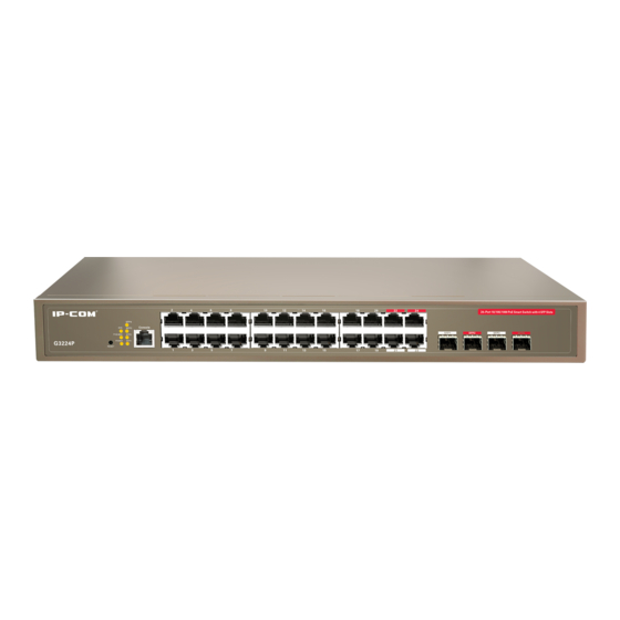
Chapter 1 Product Overview 1.1 Overview Thank you for purchasing this IP-COM product. This switch, 24-port Gigabit with 4 Shared SFP PoE Managed Switch, provides 24 10/100/1000Mbps auto-negotiation RJ45 ports, 4 1000Mbps Combo (copper/fiber) ports and one Console interface. All its RJ45 ports are PoE-capable and it can connect up to 24 IEEE 802.3af–compliant PDs (15.4W) or up to 12 IEEE 802.3at-compliant PDs (30W). -
Page 9: Specifications
1.3 Specifications 1.3.1 Hardware Specifications Item Specification Input Voltage 176 - 264VAC 50/60Hz 6A About 15W (no load); Power Consumption About 390W (full load); 24 10/100/1000Mbps auto-negotiation, PoE-capable RJ45 ports with up to 30W on each; It supports static or dynamic power allocation and can connect up to 24 IEEE 802.3af–compliant PDs (15.4W) or up to 12 IEEE 802.3at-compliant PDs (30W);... -
Page 10: Software Specifications
1.3.2 Software Specifications Features Specification Switch Volume 56Gbps (Full-duplex) Packet Forwarding 35.7Mpps Rate(full load) MAC Address Table VLAN distribution based on ports. Up to 24 can be configured; IEEE 802.1Q VLAN. Up to 128 can be configured; VLAN Protocol VLAN. -
Page 11: Package Contents
802.1P port trust mode; IP DSCP port trust mode; Bandwidth control; Up to 4-queue QoS mappings; IEEE 802.1X based on ports; Certification IEEE 802.1X based on MAC; Up to 256 MAC can be certificated; Upgrade TFTP (Trivial File Transfer Protocol) ... -
Page 12: Interfaces
Number Color Status Description Solid Proper connection to power supply System is functioning improperly. Green Solid System is functioning improperly. Blinking System is functioning properly. Power available for additional PDs PoE-MAX Green Reaching max power budget (354.2W) and no Solid more power available for another new PD An invalid link is established. -
Page 13: Fan
Note: SFP fiber ports can only work in full-duplex auto-negotiation mode. (2) RJ45 Connector The RJ45 physical connector, adopting CAT.5 twisted-pair cable, is used for connecting 10/100/1000Mbps auto-negotiation RJ45 ports as shown below: (3) SFP Connector SFP connector, which is mainly for detachable connection between optical channels, is very convenient for the test and maintenance of the optical system. -
Page 14: Chapter 2 Installation
Chapter 2 Installation The smart switch can be installed on a flat workbench or in a standard 19-inch rack. 2.1 Installing the Switch in a Rack To install the switch in a rack, observe the following procedures. To perform this procedure, you need the 19-inch rack-mount kit supplied with switch. -
Page 15: Connecting To Protective Grounding Line
2.3 Connecting to Protective Grounding Line Proper connection of protective grounding line is important for lightning protection and anti-interference. Proper connection is as follows: 2.3.1 With Grounding Bar Connect the yellow-green protective grounding cable to binding post on the grounding bar and fix the screws. (1) AC power input (2) Grounding terminal connection (3) Grounding cable protection... -
Page 16: Connecting The Power Cord
2.4 Connecting the Power Cord Step1: Connect one end of the included power cord to the switch and the other end to a nearby AC power outlet. Step2: Verify the power LED on switch's front panel. An illuminated light indicates a proper power connection. Note: As for the power cord, different countries have different standards. -
Page 17: Connecting To Pds
the same time. If both connectors are plugged in at the same time, the fiber port becomes active. The SFP module accommodates a standard SFP module with an LC connector. 2.5.4 Connecting to PDs Connect PDs (PoE powered devices, for example, 802.3at-/802.3af-compliant AP, IP telephone or IP camera) to switch. -
Page 18: Chapter 3 Login
Chapter 3 Login 3.1 Web Login 3.1.1 Preparation Item Description Installed with a network Interface card The IP address of your PC and the switch should be in the same IP and Subnet Mask network segment (It can’t be 192.168.0.1). Web Browser Microsoft IE 8.0 or higher Ethernet Cable... -
Page 19: Login Via Console Port
3.2 Login via Console Port 3.2.1 Preparation Item Description With a Console port Ethernet Cable DB9-RJ45 Console Cable 3.2.2 Configuration Preparation Step 1: Connect a terminal (PC) to the console port on the switch. Step 2: Run terminal program (for example, terminal in Windows 3.X, Hyper Terminal in Windows 9X/Windows 2000/Windows XP, an example of Windows XP is described below) on PC, select the console port that is connected to the switch and configure as below: Bits per second: 115200;... - Page 20 Figure 3-2: Connect To Figure 3-3: Port Settings Step 3: Power the switch, press Enter, input user name and password (admin/admin by default) and then press Enter again. Below screen will appear.
-
Page 21: Telnet Login
3.3 Telnet Login Take Windows XP as an example, click Start > Run and enter ―telnet 192.168.0.1‖ as seen below: Then press Enter, input the username and password ―admin/admin‖ and the following window will appear:... -
Page 22: Chapter 4 Web Configurations
Chapter 4 WEB Configurations This chapter instructs how to configure switch's functionalities and features on the Web manager. It includes below sections: Menu Submenu Description This section displays the device’s system parameters. System Info This section allows you to configure system time either by System Time synchronizing with SNTP server or specifying it manually. - Page 23 Time Range Allows users to configure absolute time, periodic time, time Time Range Management slices, etc. Displays MAC table and allows users to manually add static MAC addresses and fast binding. Allows users to configure STP, RSTP and MSTP settings. Up to 16 instances can be configured.
-
Page 24: Administration
MAC Attack Allows users to configure MAC attack defense settings. Defense Configure IP+MAC+Port+VLAN Binding, ARP filter and IP IP Filter filter settings. 802.1X Displays and allows you to configure 802.1X settings. Corporate and hotel network administrators can use this Smart Configuration section to easily configure file server port and router port. -
Page 25: System Time
Fields on the screen are described below: Field Description Firmware Version Displays switch's current firmware version and release date. Hardware Version Displays switch's current hardware version. Displays switch’s physical address. MAC Address Displays switch’s management VLAN ID. VLAN1 is preset to Management VLAN management VLAN by default. - Page 26 over packet-switched, variable-latency data networks. Simple Network Time Protocol (SNTP) is another less complex implementation of NTP. It synchronizes timekeeping between time servers and clients so that clock-dependent devices on the network can consistently provide diverse time based applications. Both SNTP server and client run over the User Datagram Protocol (UDP) on port 123.
- Page 27 Reset Click System Configuration > Reset to enter below interface. Clicking the Reset… button restores the switch to the factory default settings. Note: 1. Current settings will be lost after reset. So if you want to retain current settings, please click Save Configurations in the lower left concern of the page.
-
Page 28: System Security
Firmware Update Click System Configuration > Firmware Update to enter the interface below: This section displays current firmware version. To update the switch's firmware, click Browse… to locate and select the latest firmware and click Update. The process takes 1-2 minutes to finish. Note: Do not disconnect from power while upgrade is in process. - Page 29 SSL Protocol Structure SSL protocol can be divided into 2 layers: the bottom layer is SSL record protocol; the top layer includes SSL handshake protocol, SSL change cipher spec protocol and SSL alert protocol. SSL alert HTTP, FTP… handshake change protocol protocol cipher spec...
- Page 30 SSL Certificate Select the desired certificate to download to the switch. Select the desired SSL Key to download to the switch for SSL Key encryption. Certificate Import Import the downloaded certificate Key Import Import the downloaded key User Click Administration > System Security > User to enter interface below: Fields on the screen are described below: Field Description...
- Page 31 To change password, do as follows: On the User screen, click admin to enter below interface: Specify a new password; Enter the new password again to confirm it. Click OK. Note: Use the new password to re-log in. If you forget your password, press the hardware Reset button to reset the switch to factory default.
-
Page 32: Port Management
4.2 Port Management 4.2.1 Port Configuration Port Setup Click Port Management > Port Configuration > Port Setup to enter interface below: Fields on the screen are described below: Field Description Displays currently actual link rates and duplex modes on switch ports. "--" is Link Status displayed if a port is not connected. - Page 33 With flow control enabled on both the switch and its link partner, the switch, when encountering congestion, will send flow control frames to notify the link partner of such; upon receiving such frames, the link partner will temporarily stop sending Flow Control packets to the switch, thus avoiding packets being dropped and ensuring a reliable network.
-
Page 34: Port Mirroring
Note: 1. This device does not support half-duplex flow control. Enabling full duplex flow control can avoid packets loss, but will influence the communication speed between source interfaces and other devices. Thus, do not enable full duplex flow control on interfaces which connected to the Internet unless necessary. 2. - Page 35 A port in an aggregation group cannot be configured as a mirroring destination port. A STP-enabled and 802.1X authenticated port can't be configured as a mirroring destination port. Select a sniffer mode for a corresponding mirroring source port. "None" indicates corresponding port is not mirrored.
-
Page 36: Link Aggregation
To display specific port statistic info, click the corresponding port number. Buttons on the screen are described below: Button Description Clear Click it removes current statistic info. Refresh Click it updates current statistic info. Back Click it goes back to the interface which displays all ports’ statistic info. 4.2.2 Link Aggregation Link Aggregation Overview Link aggregation groups multiple Ethernet ports together in parallel to act as a single logical link. -
Page 37: Link Aggregation Mode
Benefits of Link Aggregation Double Bandwidth: Aggregation-enabled devices treat all physical links (ports) in an aggregation group entirely as a single logical link (port). Data transmitted to a specific host (destination address) will always be transmitted over the same port in a trunk group. - Page 38 aggregation group equals the total rate of its member ports. LACP For LACP aggregation, you must manually maintain the aggregation state of the member ports. Whether ports in LACP group are aggregation ports or not is determined by LLDPBU frame auto-negotiation. Down to 2 member ports must be included in a single aggregation group.
- Page 39 Enter a valid aggregation group number (1-6); Select Static aggregation; Select ports to join the aggregation group. Up to 8 ports and down to 2 ports can be added to each. Click OK and the group will be created. Note: Once ports in static aggregation group are linked successfully, they will be aggregated and not be affected by port speed.
- Page 40 LACP Parameters—Config To configure LACP parameters Click Port Management > Link Aggregation > LACP Protocol and below screen will be displayed: Fields on the screen are described below: Field Description System Priority Configure system priority (0-65535). The default is 32768. Displays Enable when corresponding port joins an LACP LACP Status aggregation group and Disable when the port does not join any...
- Page 41 display screen as following. Application Example of LACP Configurable range of system priority is 0-65535 and the default is 32768. When system priority is set, ports in LACP aggregation group with higher priority will be selected. The primary device of LACP aggregation group is determined by priority+management MAC address.
-
Page 42: Vlan Management
Port Configuration Considerations in Link Aggregation To share egress/ingress traffic load, member ports in an aggregation group must be set to the same configurations with respect to STP, port priorities, VLAN, port management, ARP attack defense, etc. Consistent STP Configurations: Includes STP status, P2P port, edge port, port priority, path cost, etc. Consistent port priorities Consistent VLAN Configurations in an aggregation: Includes interface type, PVID, allowed VLAN and Untag/Tag VLAN. -
Page 43: Vlan Mode
intercommunicate directly. Inter-VLAN communication can only be achieved using a router or other layer 3 devices that are able to perform Layer 3 forwarding. Compared with the traditional Ethernet, VLAN enjoys the following advantages: (1) Better management and control of broadcast activity VLANs conserve network resources by segmenting a large broadcast domain into several smaller broadcast domains or VLAN groups and restrict all broadcast traffic to the VLAN on which the broadcast was initiated. - Page 44 TPID: The 16-bit TPID field with a value of 0x8100 indicates that the frame is VLAN-tagged. Priority: The 3-bit priority field indicates the 802.1P priority of the frame (0-7). CFI: CFI is a 1-bit field, indicating whether the MAC address is encapsulated in the standard format in different transmission media.
- Page 45 Note: 1. PVID indicates the ID of a default VLAN that a port belongs to. The PVID for an access port is the ID of the VLAN it belongs to; the default PVID for a trunk/hybrid port is "1" and this value is configurable. This switch does not support ingress filter feature.
- Page 46 To add QVLAN/Access port: Click New in 802.1Q VLAN page to enter below screen: Enter 2 in VLAN ID field. Select port1 and port2 from Available Port and click to move them to Member Ports. Click OK and below screen will be displayed. Note: 1.
- Page 47 2. Up to 128 QVLANs can be added. 3. By default, all ports belong to QVLAN1. 4. When a VLAN ID is deleted, ports of this VLAN ID will belong to 802.1Q VLAN1 automatically. To add/delete an access port Click the VLAN ID of 2. Select port3 from Available Ports and click Select port2 from Member Ports and click Click OK.
- Page 48 To edit trunk port Click trunk port 1. The PVID is configurable and must be an existing VID and between 1 and 4094. If you only want the trunk port to carry some VLANs, you can delete the unwanted VLANs or add desired VLANs. Click OK.
- Page 49 To add a hybrid port 1. Click Hybrid Port to display below screen: 2. Click New and enter a port number in the Hybrid Port field. You can add multiple ports by entering "x-x" (where x represents any number between 1 and 24). For example, "1-24" denotes 24 ports while "1, 24" indicates 2 ports. 3.
-
Page 50: Port Vlan
Note: 1. Tagged VLAN and Untagged VLAN should not share the same VID. 2. Same settings should not be concurrently configured in both Add Tagged VLAN field and Delete Untagged VLAN field. 3. Settings configured in Delete Untagged VLAN field should not be concurrently the same as those in Add Tagged VLAN field. - Page 51 Click New as seen below: Enter a VLAN ID: for example 2-24, which indicates 24 VLANs, or "1, 24", which indicates two VLANs. Select port(s) from Available Ports and click to move them to Member Ports. Click OK to finish. Delete members in a port VLAN As seen above, ports 1-2 are still in VLAN1.
-
Page 52: Mac Vlan
4.3.2 MAC VLAN Overview MAC VLAN technology is the way to classify VLANs according to the MAC addresses of Hosts. MAC VLAN only takes effect on ingress untagged data. When the port receives an untag packet, the device, with the matching key words of the packets’... -
Page 53: Protocol Vlan
To create MAC VLAN 1. Click New to enter interface below: 2. Enter the MAC address you wish to configure. 3. Enter the corresponding MAC address description. 4. Select this MAC VLAN's priority (0~7 available) from the drop-down list. 5. Configure the VLAN ID mapped from MAC address. This VLAN ID must already exist in 802.1Q VLAN. 6. -
Page 54: Encapsulation Format Of Ethernet Data
If a packet is matched, the switch will add a corresponding VLAN tag to it automatically and thus the data of specific protocol can be automatically assigned to the corresponding VLAN for transmission. The network administrator can manage network clients based on their specific applications and services through protocol VLAN. Encapsulation Format of Ethernet Data At present there are two encapsulation formats of Ethernet data, Ethernet II encapsulation and 802.2/802.3 encapsulation, shown as follows:... - Page 55 Protocol Model---Config Click VLAN Management > Protocol VLAN > Protocol Model to enter interface below: Fields on the screen are described below: Field Description Displays protocol model ID (1-16). Protocol Name Displays protocol name (case-sensitive). Ether Type Displays protocol model's Ether Type (0x600-0xffff). Displays protocol model's encapsulation Frame Type (Ethernet II, LLC or Frame Type SNAP).
- Page 56 0x8137 0x8000 IS-IS 0x8809 LACP 0x888E 802.1x Configure protocol model's Frame Type. It can be configured as Ethernet II, LLC and SNAP. Click OK. Note: 1. It is not advisable to add special Type into the protocol model, such as 0X8100 and 0x88a8. 2.
-
Page 57: Voice Vlan
To add protocol VLAN 1. Click New to enter interface below: 2. Select protocol name from the pull down list. 3. Enter VLAN ID. This VLAN ID must exist in 802.1Q VLAN already. 4. Click to move ports from Available Port to VLAN-Included Port. 5. - Page 58 voice data flow or not. If the source MAC address conforms to the voice device’s OUI (Organizationally Unique Identifier) address, the packets will be regarded as voice data flow and the port which has received the voice data flow will automatically join the voice VLAN. Thus, the voice-VLAN-tagged voice traffic of voice devices connected to this port can be transmitted and enjoys higher transmission priority.
- Page 59 Voice VLAN Mode Port Type Supporting Details Access Not supported. Supported, but the default VLAN of the connected port Trunk must already exist and can’t be voice VLAN. And the default VLAN is allowed to pass on the connected port. Auto Supported, but the default VLAN of the connected port must already exist and can’t be voice VLAN.
- Page 60 Port Setup Click VLAN Management > Voice VLAN > Port Setup to enter the Voice VLAN Port Setup page as below: Fields on the screen are described below: Field Description Port Display port number. VLAN Display voice VLAN ID on corresponding port. Mode Display voice VLAN mode: auto or manual.
- Page 61 OUI Setup Click VLAN Management > Voice VLAN > OUI Setup to enter interface below: To configure OUI settings: To add a new OUI address, click Add on the OUI Setup page.
-
Page 62: Poe Management
Fields on the screen are described below: Field Description Configures source MAC address (xxxx-xxxx-xxxx) sent by voice OUI Address devices. Click select prompted mask. default Mask FFFF-FF00-0000, indicating the top 24 bits must match the OUI address and the last 24 bits are arbitrary. Descriptions of OUI address;... -
Page 63: Port Setup
Fields on the screen are described below: Field Description Configures PoE power management mode. When it is static, you can configure power allocation manually. When power supply is connected on the port, part of power will be enforced Power to be reserved for this port and can't be used by other ports. Management When it is dynamic, according to actual used power allocation, in full Mode... - Page 64 This field is available only if dynamic allocation is selected. In static Priority mode, it displays "--". Options available include High, Medium and Low. By default, this option is Low for all ports. This field is available for configuration if Static Power Distribution is selected from the power management mode pull-down list.
-
Page 65: Time Range Management
4.5 Time Range Management If a configured ACL is needed to be effective in a specified time-range, a time-range should be firstly specified in the ACL. As the time-range based ACL takes effect only within the specified time-range, data packets can be filtered by differentiating the time-ranges. -
Page 66: Device Management
Fields on the screen are described below: Field Description Time Range ID Displays corresponding time range ID. Configure this time range's absolute time (from 2000, January 1st to Absolute Time 2035, December 31th.). Periodic Time Configure this time range's periodic time (from Mon. to Sun.). Click to add a new time slice. - Page 67 • Static MAC entries, also known as "Permanent Address", which are manually added and never age out. For a small network with little change, static MAC address entry added manually may effectively reduce broadcast traffic. • Dynamic MAC entries, which can be manually added or dynamically learned and might age out. Configure MAC Address Table Entries To display MAC address entries globally Click Device Management >...
- Page 68 Bind Click this button to bind the corresponding MAC address to a specific port. And the same button changes to Bound after being clicked. To view MAC address entry: Click View and specify a MAC and a VLAN ID. Note: To view MAC address entry, you must enter the MAC address while the VLAN ID is optional.
-
Page 69: Static Mac Address
Static MAC Address Click Device Management > MAC > Static MAC Address to enter interface below: To add a static MAC address entry Click Add; enter a MAC address, specifying a VLAN ID and selecting port; then click OK. In Port VLAN mode, only MAC address and port selection are needed. -
Page 70: Stp
To delete a single MAC address, click the Delete button next to the corresponding MAC address. To delete a batch of MAC address concurrently, check corresponding check boxes and click Batch Delete. Note A certain interface’s MAC address and VLAN ID can be bound to another interface. The MAC address in the Static Address Table cannot be added to the Filtering Address Table. - Page 71 A P2P port is also capable of rapid transition. P2P ports may be used to connect to other bridges. Under RSTP/MSTP, all ports operating in full-duplex mode are considered to be P2P ports, unless manually overridden through configuration. The three protocols are mutually compatible and no conflicts or network collapse will be caused in spanning tree application.
- Page 72 Fields on the screen are described below: Field Description Enable/Disable STP globally. STP Status By default, the STP feature is disabled. Select the desired version of STP version: MSTP/RSTP/STP compatible to STP Version eliminate loops on data link layer. The default is MSTP mode. Select a BPDU processing method: Broadcast/Filter.
-
Page 73: Mstp Instance
MSTP Domain Setup Click Device Management > STP > MSTP Domain Setup to enter interface below: Fields on the screen are described below: Field Description Configure switch domain name (32 characters allowed). The Domain Name default is the device's MAC address. Configure MSTP modification level. - Page 74 Fields on the screen are described below: Field Description Instance ID: 0-15. Instance ID 0: the inter-domain spanning tree. Enable/Disable the corresponding selected instance. Only Status instance 0 is enabled by default and can’t be disabled. VLAN Mapping List Display instance's current mapping VLANs. Bridge Priority Display instance's current bridge priority.
- Page 75 To configure STP settings on a single port, click the corresponding port as seen below: Fields on the screen are described below: Field Description STP feature switch. By default, the STP is disabled. To activate the STP STP Status feature, you must enable STP both globally on the entire device and specifically on desired port(s).
- Page 76 Ports may be configured as edge ports if they are connected directly to a terminal device. These edge ports transfer directly from the blocked state Edge Port to the forwarding state without delay. As soon as the bridge detects a BPDU coming to an edge port, the port becomes a non-edge port.
- Page 77 Application Example of MST Typical Application Structure Overview As the topology shown above, Device 1 and Device 2 belong to the same domain (the same domain name, the same modification level and the same instance mapping). Make VLAN 10, 30, 100 map instance 1 and set Device 1 as the root bridge of instance 1;...
- Page 78 Set ports on Device 1 and Device 2 to Hybrid and Tagged; Set Device 1 and Device 2’s domain name to G3224P, set modification level to the default ―0‖ and configure mapping between instances and VLANs: instance 1 maps VLAN 10, 30, 100; instance 2 maps VLAN 20, 40, 200;...
-
Page 79: Lldp
4.6.3 LLDP LLDP Overview LLDP (Link Layer Discovery Protocol) is a Layer 2 protocol that is used for network devices to advertise their own device information periodically to neighbors on the same IEEE 802 local area network. The advertised information, including details such as device identification, capabilities and configuration settings, is represented in TLV (Type/Length/Value) format according to the IEEE 802.1ab standard, and these TLVs are encapsulated in LLDPDU (Link Layer Discovery Protocol Data Unit). - Page 80 Fields on the screen are described below: Field Description LLDP Enable/ Disable LLDP feature. Sending Interval The interval of sending each LLDP message (5~32768s). TTL value is used to configure neighbor info’s age time on local devices. TTL = Min (65535, (TTL multiplier × LLDP packet sending time TTL Multiplier interval)).
- Page 81 Fields on the screen are described below: Field Description Port Display corresponding port numbers. LLDP Working Status Display LLDP working status: Disable, TX, RX or TX & RX. Config Click Config to go to LLDP Batch Ports Setup page. To configure LLDP settings on a single port, click the corresponding port as seen below: Click Config on the Port Setup page to configure LLDP settings on a batch of ports concurrently.
-
Page 82: Neighbor Info
Neighbor Info Click Device Management > LLDP > Neighbor Info to display neighbor info as below: Fields on the screen are described below: Field Description Local Port Display the port which receives LLDP packet. System Name Display the neighboring device's system name. Display the port which sends LLDP packets on the neighboring Neighbor Port device. -
Page 83: Igsp
4.6.4 IGSP Overview IGMP snooping is the process of listening to Internet Group Management Protocol (IGMP) network traffic. IGMP snooping, as implied by the name, is a feature that allows a network switch to listen in on the IGMP conversation between hosts and routers. -
Page 84: Igmp Snooping
performs corresponding actions on the receiving port (resets/enables the age timer). A switch does not forward an IGMP membership report through a non-router port. When receiving a leave message When an IGMPv1 host leaves a multicast group, the host does not send an IGMP leave message, so the switch cannot know immediately that the host has left the multicast group. -
Page 85: Snmp
Fields on the screen are described below: Field Description IGSP Status Enable/disable the IGMP Snooping feature. Routing Port Age Configure routing port aging time (1-1000 sec). The default is 105s. Group-general Query Max Configure max amount of time in response to group-general query Response Time messages (1-25 sec). - Page 86 proper operation, monitor performance and detect potential problems in the Switch, switch group or network. SNMP, using polling scheme, is suitable for use in small sized network environment demanding high speed and low cost. SNMP, implemented through the connectionless UDP, can seamlessly interoperate with multiple devices. SNMP Work Mechanism The SNMP framework comprises NMS and Agent: NMS—Network Management Station NMS, is a station that runs the SNMP client software to monitor and manage...
- Page 87 You will see the Local Engine ID after enabling SNMP. This field is not configurable. Specify a Max Packet Size value, the default is 1500. Configure contact info. The default is www.ip-com.com. Here you can specify device's physical location. SNMP Version: Select V1, V2c or V3.
- Page 88 This section displays information of added user(s). Click Add to enter below interface: Note: You must create a group before you can add a user. Specify a user name, say, Jack. Specify a group name. All existing groups are displayed in the drop-down list. Select a Security Level from the drop-down list.
- Page 89 Note: You must create a view before you can create a group. Specify a group name, say, IP-COM. Specify a security level, say, auth/nopriv. Specify Read only View, Read & Write View, Notification View respectively from corresponding drop-down list. To edit groups, click the corresponding Group Name to enter the interface for modification.
- Page 90 1. Specify a view name, say, qq. 2. Specify a MIB subtree OID, say, 1.2.1. 3. Specify a view rule from the drop-down list. Enable Trap To configure SNMP Trap settings, click Device Management > SNMP > Enable Trap as below: By default, the SNMP Trap feature is enabled on each port.
- Page 91 Trap Setup To enter the interface for configuring the host to which Traps are to be sent, click Device Management > SNMP > Trap Setup as seen below. To config the host, do as follows: 1. Click Add to enter the following screen: 2.
-
Page 92: Dhcp Relay
4.6.6 DHCP Relay DHCP Relay Agent Overview The DHCP Relay Agent makes it possible for DHCP broadcast messages to be sent over routers that do not support forwarding of these types of messages. The DHCP Relay Agent is therefore the routing protocol that enables DHCP clients to obtain IP addresses from a DHCP server on a remote subnet, or which is not located on the local subnet. - Page 93 Operations supported for the Option 82: Received DHCP Processing DHCP Relay Processing Request Packets Strategy Replace the Option 82 field of the packets with the replace switch defined one and forward them. Packets with Keep the Option 82 field of the packets and forward Option82 Keep them.
- Page 94 VLAN Virtual Interface Click Device Management > DHCP Relay > VLAN Virtual Interface to enter interface below: To create a new VLAN virtual interface, click New as below: 1. Specify the VLAN ID ranging from 2 to 4094 and the VLAN ID must be existing 802.1Q VLAN ID. 2.
-
Page 95: Dhcp Snooping
To modify the VLAN virtual interface, click the corresponding VLAN ID as below: 4.6.7 DHCP Snooping DHCP Snooping Functions In computer networking, DHCP snooping is a series of techniques applied to ensure the security of an existing DHCP infrastructure. Its functions are as below: Ensure that clients only obtain IP addresses legal servers assign to them. - Page 96 Snooping entries, including clients’ MAC addresses, obtained IP addresses, ports connected to DHCP clients, ports’ belonging VLAN info, etc. Global Setup To configure DHCP snooping global settings, click Device Management > DHCP Snooping > Global Setup as below: Fields on the screen are described below: Field Description Enable/Disable DHCP snooping feature globally.
- Page 97 Fields on the screen are described below: Field Description Port The corresponding port number. Configure the current port's DHCP snooping property (trust or Port Property untrust). Enable/Disable option 82. Option 82 records DHCP clients' location Option82 Status info. When DHCP snooping receives DHCP packets, it will process these packets according to whether Option 82 included, processing strategy Option82 Strategy of user configuration and fill pattern, and then forward them to...
-
Page 98: Qos
Fields on the screen are described below: Field Description Display user binding digits in the list. IP Address Display the user binding's IP address. MAC Address Display user binding's MAC address. VLAN Display user binding's VLAN ID. Port Display user binding's port number. Remaining Lease Time Display user binding's remaining lease time. - Page 99 802.1Qtagged Ethernet frame Below displays a detailed view of an 802.1Q tag. 802.1p priority, also known as class of service (CoS), is contained in the priority field of the TCI. It is made up of 3 bits and with available values ranging from 0 to 7. 802.1QTag The 802.1P priority tags are mapped to the Switch’s priority queues as follows: 802.1P priority...
- Page 100 Strict Priority Queuing Strict Priority Queuing is specially designed to meet the demands of critical services or applications. Critical services or applications such as voice are delay-sensitive and thus require to be dequeued and sent first before packets in other queues are dequeued on a congested network. For example, assume that 4 egress queues 3, 2, 1 and 0 with descending priority are configured on a port.
- Page 101 Then the queue with the lowest priority can be ensured of, at least, 10 Mbps bandwidth, thus avoiding the disadvantage of SP queue-scheduling algorithm that packets in low-priority queues may not be served during a long time. Another advantage of WRR queue-scheduling algorithm is that though the queues are scheduled in turn, the service time for each queue is not fixed, that is to say, when a queue is emptied, the next queue will be scheduled immediately.
-
Page 102: Port Priority
DSCP To configure DSCP priority settings, click QoS > QoS Configuration > DSCP as below: Note When congestions occur, the device will map DSCP values to CoS values according to the configured mapping relationships at first. Then according to the CoS-queue mapping table, it assigns packets with DSCP priority to queues which CoS priority corresponds to. -
Page 103: Traffic Control
To configure port priority settings on multiple ports, click Config. Note For packets with CoS and DSCP enabled, DSCP takes effect. For packets with only CoS enabled, CoS takes effect. For packets without CoS and DSCP, port priority takes effect. 4.7.2 Traffic Control Bandwidth Control Rate limit functions to control the ingress/egress traffic rate on each port via configuring the available bandwidth of... - Page 104 To configure rate limit on multiple ports, click Config. Storm Constrain Storm Constrain function allows the switch to filter broadcast, multicast and unknown unicast frames in the network. If the transmission rate of the three kind packets exceeds the set bandwidth, the packets will be automatically discarded to avoid network broadcast storm.
-
Page 105: Acl
To configure storm constrain settings on a specified port, click the corresponding port. To configure storm constrain settings on multiple ports, click Config. 4.7.3 ACL ACL Overview As traffic increases and network grows, network security appears more and more important. Pack filter can effectively block unauthorized users from accessing network and control traffic volume on the network for the purpose of conserving network resources. -
Page 106: Mac Based Acl
MAC Based ACL Click QoS > ACL > MAC Based ACL to enter interface below: This page displays all existing MAC based ACLs and rules thereof. To delete an existing MAC based ACL Select the ACL you wish to delete from the ACL drop-down list and click on the Delete ACL button. To create MAC based ACL Click Create ACL, enter required settings and then click OK. -
Page 107: Ip Based Acl
Select an ACL Click Add Rule. Configure required settings and click OK. Fields on the screen are described below: Field Description Select ACL Select an existing ACL and specify rules for it. Specify a priority for a given rule, which determines match scheduling order. - Page 108 This page displays all existing IP based ACLs and rules thereof. To delete an existing IP based ACL Select the ACL you wish to delete from the ACL drop-down list and click on the Delete ACL button. To batch delete rules in an ACL Select the ACL and rules thereof you wish to delete, and click on the Delete Rule button.
- Page 109 Protocol Select a protocol to match. Specify source IP and destination IP of packets for a rule to match. Source/Destination IP Note: If Any is selected, the rule will match and apply to all packets with whatever source IP/destination IP. Specify source port number to match TCP/UDP messages.
-
Page 110: Security
To create port ACL binding, click New, specify a port that you wish to apply a given ACL, configure required settings and click OK. To delete a specific Port ACL binding, click Delete on the port ACL binding page as below: Select the port and the ACL you wish to unbind and then click OK. - Page 111 Click Security > Attack Defense > ARP Attack Defense to enter interface below: Fields on the screen are described below: Field Description By default, the Port ARP Rate limit feature is disabled. Port ARP Rate Note: ARP rate limit enabled ports will check current ARP rate every 60s and Limit discard ARP messages received if current ARP RX rate exceeds the set ARP RX rate threshold.
- Page 112 To configure ARP rate limit status and ARP RX rate for a single port Click the corresponding port to enter the configuration page. To configure ARP rate limit status and ARP RX rate for a batch of ports simultaneously Click Config to enter corresponding page for configuration. Worm Attack Defense Worm Attack Defense prevents virus/worm infected PCs being spread to targeted healthy PCs and the whole network by scanning for security failures.
- Page 113 To defend against known viruses, you need to add them to the device and enable the worm attack defense feature. 1. Click New to enter screen below 2. Enter the virus name, say, SQLSlammer. 3. Specify a protocol, say, TCP or UDP. 4.
- Page 114 To undo defense against this virus attack, simply uncheck it or directly click Delete. To delete a batch of items simultaneously, simply click Delete All. To edit an existing virus attack defense entry, simply click it to enter the corresponding interface. Re-configure it and then click OK.
- Page 115 This section displays and allows you to configure the DoS Attack Defense settings. By default all DoS Attacks are disabled. For detailed description of each DoS attack, click the Help button on the web page. MAC Attack Defense MAC Attack Defense prevents the device from learning large amount of unnecessary source MAC addresses so that forwarding capability will not be degraded due to an oversized MAC address table.
- Page 116 To set a MAC address learning limit on a batch of ports concurrently Click Config to enter corresponding page for configuration. Address Limit: Configure it according to the actual network environment. By default, the number of MAC addresses that each port can learn is not limited. Unknown MAC Address Drop: If enabled, corresponding port(s) will discard packets where source MAC addresses are not in the MAC address table when reaching the set address limit, otherwise, continue forwarding.
-
Page 117: Ip Filter
4.8.2 IP Filter After you configured and activated the IP+MAC+Port+VLAN Binding settings, the device will perform strict packet filter to further secure the network. To search for IP+MAC+Port+VLAN Binding entries, smart binding. Click Security > IP Filter > Add Binding Entry to enter interface below: Click Search host. - Page 118 To add IP+MAC+Port+VLAN Binding entries manually 1. Click Security > IP Filter > Add Binding Entry and on the appearing interface, select Add IP+MAC+Port VLAN Binding entry manually. Enter an IP address, for example "192.168.10.1". Enter a MAC address, for example "aaaa-bbbb-cccc". Enter a port number, for example "24".
- Page 119 Fields on the screen are described below: Field Description Determine whether to connect selected port to gateway. Yes: Connect selected port to gateway and IP Filter is unavailable for configuration. Connect to No: Do not connect selected port to gateway and IP Filter is available for Gateway configuration.
-
Page 120: Mac Filter
Delete binding entry To delete a batch of binding entries concurrently, click the Batch Delete button on the IP+MAC+Port+VLAN Binding screen; to delete a single binding entry, on the IP+MAC+Port+VLAN Binding screen, click the Delete button at the end of the entry. Note After you deleted a binding entry on a port, go to Port Filter Setup interface to check whether the IP filter is disabled, if not, such port will not be able to receive any IP packets. -
Page 121: 114
To add MAC address filter 1. Click Add to enter interface below: 2. Specify the VLAN ID in the VLAN field. Valid range is 1-4094 and the VLAN ID must already exist. 3. Enter the MAC address you wish to filter, such as ―0000-aaaa-aaaa‖. 4. - Page 122 802.1X Re-authentication 802.1X Re-authentication re-authenticates users that already pass authentication using timer or message trigger. With 802.1x Re-authentication enabled, the switch periodically checks users' connection status. If a user is detected not responding to re-authentication messages for a certain time length, it will then be disconnected. If it wishes to reconnect to the device, it must initiate an 802.1x authentication again via client software.
- Page 123 Fields on the screen are described below: Field Description Configure global 802.1X status. Enable: Enable 802.1X feature globally. Disable: Disable 802.1X feature globally. Global Mode By default, the 802.1X feature is disabled globally on the device. Note: 802.1X settings take effect only when the 802.1X feature is enabled on both the device and specific ports.
-
Page 124: X Port Statistics
To configure MAC based 802.1X settings on a single port Click the corresponding port. Select Enable from Port Mode drop-down list and Enforce Authorization from Port Control Mode drop-down list. Select MAC from Access Control Method drop-down list. Specify the maximum access number field. The default is 256. Click OK and the 802.1X feature will be enabled. -
Page 125: Smart Configuration
Fields on the screen are described below: Field Description Port Corresponding Port Number EAP: EAP packets sent from ports to 802.1x clients. RADIUS:RADIUS packets sent from ports to 802.1x server. EAP: EAP packets received from 802.1x clients to ports. RADIUS: RADIUS packets sent from ports to 802.1x server. Clear Clear all statistics. - Page 126 automatically set to 5 respectively. If a group of ports are set to connect virtual disk servers, flow control Virtual Disk Server Port will be automatically enabled on them and port priority will be automatically set to 5 respectively. Ports connect to routers (router port) will be automatically enabled as Router Port mirrored ports and apply port priority of 5.
-
Page 127: For Business
4.9.2 For Business Smart Port Setup Click Smart Configuration > For Business > Smart Port Setup to enter interface below (Specify file server port and router port according to your practical needs.): Fields on the screen are described below: Field Description File Server Port Specify a port to connect to a file server. -
Page 128: Maintenance
Smart Port Check-up Click Security > For Business > Smart Port Check-up, on the appearing interface you can check hotel smart port settings. Click Check-up to check smart port settings and it will prompt you with tips if detecting changes in the settings. - Page 129 Logs To view system logs, click Maintenance > Syslog > Logs as below: Log Setup To configure log settings, click Maintenance > Syslog > Log Setup as below: Fields on the screen are described below: Field Description Enable Logging Enable/disable Log feature. By default, it is enabled. Enable Server Check to enable log server.
-
Page 130: Network Diagnostics
4.10.2 Network Diagnostics This device provides Cable check-up, Ping check-up and Tracert check-up functions for network diagnose. Cable Check-up On this device, you can test the current cabling situations on the specified Ethernet interfaces, pair A, B, C, D connection status and pair length included. Click Maintenance >... - Page 131 Fields on the screen are described below: Field Description Need to specify the destination host IP which should be in the same Destination IP Address network segment as this device. This field is blank by default. Sending Times Configure ICMP request sending packets (1~10). The default is 4. Configure ICMP request packets length (18~512 bytes).
-
Page 132: Logout
1.1.1.2 included), thus Device A obtains the first L3 device’s IP (1.1.1.2); (3) Device A re-transmits an IP packet to Device D and TTL value is 2. (4) Device C replies with an ICMP error of TTL timeout, thus Device A obtains the second L3 device’s IP (1.1.2.2);... -
Page 133: Save Configurations
4.12 Save Configurations Configurations on switch will be lost if they are not saved before switch reboots. So do save them on this screen before you reboot the switch. 1. Save Current Settings Use this feature to save device current configurations to ensure you will still have them on the switch even after device restarts. -
Page 134: Chapter 5 Cli Configuration
"con" field automatically. To go back to previous directory, press the "/" key. "/" is invalid in "IP-COM #". To activate a command, press Enter after you finished entering it. -
Page 135: Config System Info
Note: Enter multiple-port view 5.3.2 Config System Info IP-COM (config)# snmp-server chassis-id G3224P Note: Config device name as G3224P IP-COM (config)# snmp-server contact ip-com Note: Config contact as ip-com IP-COM (config)# snmp-server location Shenzhen Note: Config location as Shenzhen 5.3.3 Config IP Address Manually IP-COM (config)# ip address 192.168.111.217 255.255.255.0... -
Page 136: System Time Configuration
IP-COM# no service telnet Note: Disable Telnet service 5.3.6 System Time Configuration IP-COM# clock set 14:09:30 4 11 2012 Note: Manually set system date and time to Apr 11 2012 and 14:09:30 respectively IP-COM(config)# sntp enable Note: Enable SNTP server... -
Page 137: Reset And Reboot
IP-COM#archive startup-config 192.168.111.79:mib.conf Note: Save firmware to local hard drive via a TFTP server 5.3.9 Web Login Timeout Configuration IP-COM(config)# http redirect timeout 300 Note: Config web login timeout interval as 300 seconds IP-COM# show http redirect timeout Note: View web login timeout settings 5.3.10 Config Port Settings... -
Page 138: Port Mirroring Configuration
IP-COM(config)# monitor destination interface gigabitethernet 0/8 Note: Config port 8 as the mirroring destination port IP-COM(config)# monitor source interface range gigabitethernet 0/1-3 rx Note: Config ports 1-3 as mirroring source ports and sniffer mode as Ingress. IP-COM(config)# monitor source interface range gigabitethernet 0/4-5 tx Note: Config ports 4-5 as mirroring source ports and sniffer mode as Egress. -
Page 139: Config Port Rate Limit
5.3.13 Config Port Rate Limit IP-COM(config)# interface range gigabitethernet 0/1 IP-COM(config-if)# rate-limit input 100 Note: Set ingress rate limit to 100M on port 1 IP-COM(config-if)# rate-limit output 10 Note: Set egress rate limit to 10M on port 1 IP-COM(config-if)# no rate-limit input... -
Page 140: Vlan Configuration
Note: Config source and destination IP algorithm View aggregation info IP-COM# show aggregate-port Note: View aggregation group IP-COM# show lacp all counters Note: View LACP packet statistics IP-COM# show lacp all internal Note: View peer LACP port info IP-COM# show lacp all neighbor... - Page 141 Note: Enter the directory of port 2 IP-COM(config-if)# switchport mode trunk Note: Set port 2 to a Trunk port IP-COM(config-if)# switchport trunk native vlan 1 Note: Set the PVID of Trunk port 2 to 1 IP-COM(config-if)# switchport trunk allowed vlan all...
- Page 142 IP-COM(config-if)# switchport trunk native vlan 2 Note: Set the PVID of Trunk port 24 to 2 IP-COM(config-if)# switchport trunk allowed vlan add 1,2 or 1-2 Note: Set Trunk port to carry VLANs 1-2 IP-COM(config-if)# switchport trunk allowed vlan except 2...
- Page 143 Note: Set port 10 to carry tagged VLANs 10-20 IP-COM(config-if)# switchport hybrid allowed vlan untagged add 4094 Note: Set port 10 to carry untagged VLAN4094 IP-COM(config-if)# switchport hybrid allowed vlan untagged except 30 Note: Set port 10 to carry all untagged VLANs except VLAN30 IP-COM(config-if)# switchport hybrid allowed vlan untagged remove 4094 Note: Delete VLAN4094 from untagged VLANs;...
-
Page 144: Mac Vlan
IP-COM# configure terminal IP-COM(config)# vlan 2 Note: Create QVLAN2 IP-COM(config)# mac-vlan 0000.0000.0001 vl1 vlan 2 cos 0 Note: Add MAC VLANs whose MAC address is 0000.0000.0001. It is described as v11 and corresponds to vlan2 with cos 0. IP-COM# configure terminal IP-COM(config)# no mac-vlan 0000.0000.0001... -
Page 145: Voice Vlan
IP-COM# configure terminal IP-COM(config)# interface gigabitethernet 0/6 Note: Enter port settings interface IP-COM(config-if)# switchport voice vlan mode auto Note: Set voice VLAN mode of port 6 to auto IP-COM(config-if)# switchport voice vlan mode manual Note: Set voice VLAN mode of port 6 to manual... -
Page 146: Mac Configuration
IP-COM(config)# mac-address-table static 0000.0000.0002 interface gigabitethernet 0/1 vlan 1 Note: Add static MAC address of 0000.0000.0002 to port 1 of VLAN1 IP-COM(config)# no mac-address-table static Note: Delete all static MAC addresses IP-COM(config)# no mac-address-table static 0000.0000.0002 interface gigabitethernet 0/1 vlan 1 Note: Delete a single static MAC address... -
Page 147: Qos Configuration
Note: Set Scheduling Scheme to SP IP-COM(config)# QoS scheduler wrr Note: Set Scheduling Scheme to WRR IP-COM(config)# wrr-queue bind-width 1 6 10 31 Note: Assign QoS weights: 1, 6, 10 and 31 to queues: 1, 2, 3 and 4 respectively... -
Page 148: Stp Configuration
IP-COM(config)# spanning-tree hello-time 1 Note: Set Hello Time to 1s IP-COM(config)# spanning-tree forward-time 4 Note: Set Forward Delay to 4s IP-COM(config)# spanning-tree mstp max-hops 30 Note: Set max hops to 30 IP-COM(config)# spanning-tree mstp 0 priority 32768 Note: Set instance priority... - Page 149 Note: Delete current forward delay setting and restore it to the default 15 IP-COM(config)# no spanning-tree mstp max-hops Note: Delete max hop setting and restore it to the default 20 IP-COM(config)# no spanning-tree mstp 0 priority Note: Delete instance bridge priority setting and restore it to the default 30768 ...
- Page 150 IP-COM(config-if)# no spanning-tree link-type point-to-point Note: Delete current p2p port setting and restore it to factory default IP-COM(config-if)# spanning-tree mstp 10(0-15) cost default Note: Set path cost to 802.1t auto mode in the instance IP-COM(config-if)# spanning-tree mstp 0 cost 2000...
-
Page 151: Igmp Configuration
IP-COM# show spanning-tree enable-instance Note: Display all enable-instances and linkup port info IP-COM# show spanning-tree region-configuration Note: Display switch’s domain info 5.3.22 IGMP Configuration Enter configuration directory: IP-COM # configure terminal Enable/disable IGMP IP-COM(config)# ip igmp snooping ivgl Note: Enable IGMP... -
Page 152: Time Range Management
Note: Disable IGMP port fast leave 5.3.23 Time Range Management Configure time range IP-COM(config)# timerange 99 absolute start time 11 23 2010 end time 08 16 2013 Note: Configure absolute time IP-COM(config)# timerange 67 weekday 8 Note: Config periodic time... -
Page 153: Poe Management
Delete time range IP-COM(config)# no timerange 67 Note: Delete time range IP-COM(config)# no timerange 12 periodic start time 03:40 end time 05:35 Note: Delete time slices View time range IP-COM# show timerange Note: View time range 5.3.24 PoE Management ... -
Page 154: Acl Configuration
IP-COM(config-mac-nacl)# rule 1 deny vlan 2 eth-type any src-mac any dst-mac any Note: Add rule 1 and deny all packets passing IP-COM(config-mac-nacl)#rule 2 deny vlan 1 eth-type any src-mac aaaa.aaaa.aaaa src-mac-mask any dst-mac any dst-mac-mask any Note: Add rule 3, and deny all packets at the source MAC address of "aaaa.aaaa.aaa" passing. - Page 155 IP-COM(config-ip-nacl)# rule 2 rate-limit 64 ip src-ip 192.168.10.1 src-ip-mask any dst-ip any Note: Add rule 2, and set RX rate of packets with the source IP address of 192.168.10.1 to 64kbps Note: Deny: Deny packets matching rule passing; IP: Specify protocol type;...
-
Page 156: Dos Attack Defense Configuration
IP-COM(config)# mac access-list 125 Note: Enter ACL 125 IP-COM(config-mac-nacl)# no bind-to interface range gigabitethernet 0/1 Note: Undo binding between ACL 125 and port 1 IP-COM(config)# ip access-list extended 1 IP-COM(config-ip-nacl)#no bind-to interface range gigabitethernet 0/1-4 Note: Enter ACL 1, and undo binding between ACL 1 and ports 1-4 ... -
Page 157: Worm Attack Defense Configuration
IP-COM(config)# no ip deny blat-udp Note: Disable BLAT UDP Attack Defense 5.3.27 Worm Attack Defense Configuration IP-COM(config)# filter aaa tcp 10 on Note: Enable filter of TCP virus packets with destination port number of 10 IP-COM(config)# filter aaa tcp 10 off... -
Page 158: Config Mac Attack Defense
IP-COM(config-if)# ip arp inspection trust IP-COM(config-if)# ip arp inspection limit rate 200 Note: Enable ARP attack defense on port 10 and configure ARP RX rate to 200PPS IP-COM(config)# interface rang gigabitethernet 0/11-20 IP-COM(config-if)# ip arp inspection trust IP-COM(config-if)# ip arp inspection limit rate 150 Note: Enable ARP attack defense on ports 11-20 and configure ARP RX rate to 150PPS ... -
Page 159: Ip Filter Configuration
Note: Add IP+MAC+Port+VLAN binding entry: bind the IP address of 192.168.0.5 and MAC address of 0000.0000.0006 to port 1 IP-COM(config)# ipmacbind 192.168.0.5 0000.0000.0002 4094 interface gigabitethernet 0/5 Note: Add IP+MAC+Port+VLAN binding entry: bind the IP address of 192.168.0.5 and MAC address of 0000.0000.0002 to port 5 in VLAN4094... -
Page 160: Dhcp Relay
Display IP+MAC+Port+VLAN binding entry IP-COM# show ipmacbind Note: Display all IP-MAC-Port-VLAN binding entries IP-COM# show ipmacbind interface gigabitethernet 0/1 Note: Display port filter settings and IP+MAC+Port+VLAN binding entries on a single port IP-COM# show ipmacbind interfaces Note: Display all port filter settings and IP+MAC+Port+VLAN binding entries 5.3.31 DHCP Relay... - Page 161 VLAN virtual interface configuration IP-COM(config)# interface vlan-interface 2 Note: Enter VLAN virtual interface 2 IP-COM(vlan-if)# ip address 2.2.2.2 255.0.0.0 Note: Configure IP address and subnet mask of virtual interface 2 IP-COM(vlan-if)# enable Note: Enable virtual interface 2 IP-COM(vlan-if)# no enable Note: Disable virtual interface 2 ...
-
Page 162: Dhcp Snooping
IP-COM(config)# no ip dhcp snooping Note: Disable global DHCP snooping IP-COM(config)# ip dhcp snooping verify mac-address Note: Enable verifying MAC address IP-COM(config)# no ip dhcp snooping verify mac-address Note: Disable verifying MAC address Port settings IP-COM(config)# interface range gigabitethernet 0/7... -
Page 163: Snmp Agent Configuration
Note: Set community name to private, access right to read only IP-COM(config)# snmp-server community IP-COM rw Note: Specify community name as ip-com and access right as read & write IP-COM(config)# snmp-server packetsize 1500 Note: Set SNMP packet size to 1500 IP-COM(config)# snmp-server version 1&2c... - Page 164 Note: Enable Authentication Trap on the Switch IP-COM(config)# snmp-server trap type 31 Note: Enable all Trap features the Switch supports IP-COM(config)# snmp-server trap interface range fastethernet 0/1-24 Note: Enable trap features mentioned above on all ports View Trap settings IP-COM# show snmp-server traps ...
-
Page 165: Log Configuration
Note: Display log server IP-COM# show logging all Note: Display all system logs IP-COM# show logging alert / critical / debug / emergency / error / informational / notice / warning Note: Display logs by 9 severity levels Clear logs... -
Page 166: Configuration
802.1X Global Setup IP-COM(config)# aaa dot1x enable Note: Enable 802.1X IP-COM(config)# no aaa dot1x enable Note: Disable 802.1X IP-COM(config)# radius-server host 192.168.0.78 Note: Specify the IP address of 802.1X server. Note that it must be on the same net segment as the Switch IP-COM(config)# radius-server key WinRadius Note: Specify a key for the 802.1X server... -
Page 167: Save Configurations
IP-COM# show dot1x all Note: Display 802.1X global settings and port status IP-COM# show dot1x statistics Note: Display all ports’ status IP-COM# show dot1x interface gigabitethernet 0/1 Note: Display a single port’s status 5.3.36 Save Configurations IP-COM# copy running-config startup-config Note: Save current settings IP-COM# copy running-config 192.168.111.79: mib.conf... - Page 168 Note: Disable port. IP-COM(config-if)# no port-isolated Note: Disable port isolation. Display settings on port IP-COM# show interface gigabitethernet 0/3 Note: Display basic settings on interface 3. IP-COM# show interface status Note: Display basic settings on all interfaces.
-
Page 169: Appendix 1 Glossary
Appendix 1 Glossary SNTP Simple Network Time Protocol (SNTP), using UDP datagram packets at the transport layer, is a networking protocol for clock synchronization between computer systems over packet-switched, variable-latency data networks. HTTP The Hypertext Transfer Protocol (HTTP) is an application protocol for distributed, collaborative, hypermedia information systems. - Page 170 authenticator, and the authenticator forwards the credentials to the authentication server for verification. If the authentication server determines the credentials are valid, the supplicant (client device) is allowed to access resources located on the protected side of the network. Port Mirroring Network Engineers or Administrators use port mirroring to copy traffic from multiple ports to the mirroring destination port for analyzing and debugging data or diagnosing errors on a network.
- Page 171 A denial-of-service attack (DoS attack) or distributed denial-of-service attack (DDoS attack) is an attempt to make a machine or network resource unavailable to its intended users. Perpetrators of DoS attacks typically target sites or services hosted on high-profile web servers such as banks, credit card payment gateways, and even root name servers.
- Page 172 and records any packet loss. The results of the test are printed in the form of a statistical summary of the response packets received, including the minimum, maximum, and the mean round-trip times, and sometimes the standard deviation of the mean. Port VLAN Port-based VLANs are created by assigning ports to a VLAN.
- Page 173 text-oriented communications facility between Telnet server and client using a virtual terminal connection. It uses the TCP protocol. TFTP TFTP (Trivial File Transfer Protocol) is a file transfer protocol notable for its simplicity. It is generally used for automated transfer of configuration or boot files between machines in a local environment. Different from FTP, It has been implemented on top of the User Datagram Protocol (UDP) using port number 69 and thus can penetrate multiple firewalls.
-
Page 174: Appendix 2 Technical Support
Appendix 2 Technical Support If any problem occurs while in use, please feel free to go to www.ip-com.com.cn to find a solution or email your problems to: info@ip-com.com.cn. We will be more than happy to help you out as soon as possible. -
Page 175: Appendix 3 Safety And Emission Statement
Appendix 3 Safety and Emission Statement CE Mark Warning This is a Class A product. In a domestic environment, this product may cause radio interference, in which case the user may be required to take adequate measures NOTE: (1) The manufacturer is not responsible for any radio or TV interference caused by unauthorized modifications to this equipment.
Need help?
Do you have a question about the G3224P and is the answer not in the manual?
Questions and answers