Table of Contents
Advertisement
Advertisement
Table of Contents

Related Manuals for IP-COM F1226P


Summary of Contents for IP-COM F1226P
-
Page 2: Copyright Statement
IP-COM Networks Co., Ltd. If you would like to know more about our product information, please visit our website at www.ip-com.com.cn. -
Page 3: Safety Guidelines
This document was created primarily for the system administrator who wishes to install and configure the F1226P in a network. This user guide assumes that the reader has a general understanding of switch platforms and a basic knowledge of Ethernet and networking concepts. -
Page 4: Table Of Contents
Contents Chapter 1 Introduction ..............................4 1.1 Product Overview ............................4 1.2 Features ................................4 1.3 Physical Description ............................4 1.4 Package Contents ............................6 Chapter 2 Installation ..............................7 2.1 Installation Considerations ..........................7 2.2 Installing the Switch ............................7 2.3 Hardware Connection ............................ -
Page 5: Chapter 1 Introduction
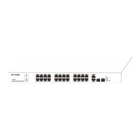
Plus, it also provides a complete package of enterprise-class features including VLAN, 802.1Q VLAN, QoS, SNMP, port mirroring and port aggregation, STP, PoE, etc. By default, the F1226P distributes power dynamically and each PoE capable port supplies power at IEEE802.3at standard. - Page 6 Status LEDs RESET button PoE-MAX Figure 1 Switch Front Panel 1. RJ45 ports: 24 10/100Mbps and 2 10/100/1000Mbps ports with autosensing and auto-negotiation capabilities 2 1000Mbps SFP fiber ports 2. Status LEDs: Link/Act1~24: 24 10/100M port status LEDs ...
-
Page 7: Package Contents
Green ( Solid Link is established on the port. G1/G2 only G1~G2 lights up when Blinking Packet transmission or reception is occurring on the port. operating at No link is established on the port. 1000M) Link is established or packet transmission is occurring on Solid the port. -
Page 8: Chapter 2 Installation
Chapter 2 Installation 2.1 Installation Considerations To keep the switch in optimum working condition and prolong its life time, follow instructions below : Please keep the switch in a dry and well ventilated environment. For desktop installations, place the device on a flat table or shelf surface; for rack-mount installations, use a 19-inch (48.3-centimeter) EIA standard equipment rack that is grounded and physically secure. -
Page 9: Hardware Connection
2). Attach the supplied mounting brackets to the side of the switch. 3). Insert the screws provided in the rack-mount kit through each bracket and into the bracket mounting holes in the switch. 4). Align the mounting holes in the brackets with the holes in the rack. 5). - Page 10 2. Connecting devices to the switch’s RJ45 ports Connect each PC to an RJ45 port on the switch’s front panel (Figure 7) with an Ethernet cable. Figure 7: Connect PC to Switch’s RJ45 Port 3. Connect PDs Connect PDs (PoE powered devices, for example, 802.3at-/802.3af-compliant AP, IP telephone or IP camera) to the switch.
-
Page 11: Chapter 3 Configuration Guide
Chapter 3 Configuration Guide 3.1 Getting Started with Switch Management Interface 3.1.1 System Requirements This Switch provides a built-in browser interface that enables you to configure and manage it using a standard Web browser such as Microsoft Internet Explorer. The following hardware and software facilities are required to run the applications described in this manual: •... -
Page 12: Introduction To The Web Browser Interface
Enter “admin” in both the User Name field and the Password field and click Login. This will open the Web-based user interface as seen below. 3.1.3 Introduction to the Web Browser Interface This section introduces the Web browser interface that enables you to configure and manage your switch. The Menus and submenus on the web browser interface are described below: Menu Submenu... - Page 13 Force device to restart. Configurations will be erased Reboot after Reboot. So please do save them before you restart the switch. Firmware Upgrade Upgrade firmware. Display and allow you to config basic port parameters, Port such as link status, speed/duplex, MAC address Configuration learning, flow control (enabled by default) and broadcast storm control (enabled by default), etc.
-
Page 14: Administration
loopback detection, Auto-Wakeup and Wakeup Time Interval) Port Configure priority and path cost settings for each port; Configuration Display port role and status in spanning tree. IGSP Configure IGMP snooping settings. SNMP Configure SNMP status, community name and Configuration read/write settings. SNMP Trap Enable/disable Trap and configure Trap destination host... - Page 15 Fields on the screen are described below: Field Description Firmware Version Display switch's current firmware version Hardware Version Display switch's current firmware version Display switch’s physical address MAC Address Management VLAN1 is preset to management VLAN by default. VLAN Enable DHCP client to obtain an IP address automatically from the DHCP server on network.
-
Page 16: User Management
This field specifies the length of time a learned dynamic MAC Address will remain in the forwarding table without being accessed (that is, how long a learned MAC Address is MAC Age allowed to remain idle). The MAC Address Aging Time can be set to any value between 60-3000 seconds. -
Page 17: Reboot
3.2.4 Reboot Here you can reboot the switch. To reboot the switch, click Reboot… on the screen below. 3.2.5 Firmware Upgrade The switch software is upgradeable, and enables your switch to take advantage of improvements and additional features as they become available. The upgrade procedure assumes that you have downloaded or otherwise obtained the firmware upgrade and that you have it available on your computer. - Page 18 Browse: Click to locate the upgrade file. Upgrade: Click to update the software. Note: Software upgrade takes about 5 minutes. Please wait for the process to complete and do not disconnect network and power connection during the process. Click OK on the window below to complete the process and system will return to management interface.
-
Page 19: Port Management
Note: 1. Do NOT interrupt power and network connections during software upgrading. If network is interrupted during the process, you must re-enter the upgrade screen and re-upgrade the software. 2. To return to management interface when you already enter the upgrade screen, simply click Back. But you cannot return to the management interface if upgrade is in process or upgrade fails. - Page 20 To configure a port, select a port number from the drop-down list, say, 1. Fields on the screenshot above are described below: Field Description Select Port Select a port number from the drop-down list that you wish to configure. State Enable/Disable a port.
-
Page 21: Port Mirroring
such; upon receiving such frames, the link partner will temporarily stop sending packets to the switch, thus avoiding packets drop and ensuring a reliable network. Storm Control Enable/disable the broadcast storm control feature or restrict the max number of broadcast packets transmitted and received on active port(s). With broadcast storm control enabled, broadcast traffic exceeds the max value (2000pps), system will drop the excessive frames to reduce the traffic into a restricted ratio, thus effectively controlling various storms, avoiding network congestion and ensuring a reliable... - Page 22 To configure port mirroring settings, do as follows: Select a mirroring destination port (only one). Select a mirroring source port (you can select one or more mirroring source ports but only one mirroring destination port). Select a proper Sniffer Mode (mirroring mode): None, Ingress, Egress or Egress & Ingress. Click OK to complete your settings.
-
Page 23: Rate Limiting
You can select what type of data to count, for example RX & TX, and system will count and display the number of packets received & transmitted on each active port. Click Refresh to display updated statistic data or click Clear to clear current statistic data. -
Page 24: Link Aggregation
Fields on the screen are described below: Field Description Port Select a port number from the drop-down list. Select a Tx (Tranmit) rate for a selected port. Options available are 256k, 512k, 1M, 2M, 4M, 8M, 10M, 16M, 32M, 64M and 100M. The default is “--”, which means the Tx Rate (kbps) given port transmits packets at an actual link rate. - Page 25 Aggregation-enabled devices treat all physical links (ports) in an aggregation group entirely as a single logical link (port). Member ports in an aggregation group share egress/ingress traffic load, delivering a bandwidth that is multiple of a single physical link. Link aggregation provides redundancy in case one of the links fails, thus reliability could be maintained.
-
Page 26: Poe
To configure link aggregation settings, do as follows: Select an aggregation algorithm from the Aggregation Algorithm drop-down list. Available options include port number Source MAC, Dest MAC and Source & Dest MAC. The default is Source & Dest MAC. Select port numbers from Group Member. Select Enable from Link Aggregation drop-down list box. -
Page 27: Global Configuration
802.3at, offers 25.50 W. Powered device A powered device (PD) is a device powered by a PSE and thus consumes energy. Examples include wireless access points, IP Phones, and IP Cameras. 3.4.1 Global Configuration Click PoE Management > Global Settings to enter Global Settings screen and you can a).Configure power management mode;... - Page 28 b). View the amount of power supplied to connected PDs and PD class. If Dynamic Allocation is selected on the Global Settings screen, the Static Allocation field on the Port Configuration screen will be unconfigurable; if Static Allocation is selected, the Priority on the Port Configuration screen will gray out and become unconfigurable.
-
Page 29: Device Management
each device and power levels of 0, 1, 2 and 3. IEEE 802.3at: IEEE 802.3af: Compatible with IEEE 802.3af, the IEEE 802.3at PoE standard provides up to 30W of power to each device and power levels of 0, 1, 2, 3 and 4. This field is available only if dynamic allocation is selected. -
Page 30: Benefits Of Vlans
treated as in the same broadcast domain and communicate as if they were on the same net segment, regardless of their physical locations. Logically, a VLAN can be equated to a broadcast domain, because broadcast packets are forwarded to only members of the VLAN on which the broadcast was initiated. Different VLANs cannot intercommunicate directly. - Page 31 4. 802.1Q VLAN Tagged VLAN As defined in IEEE 802.1Q, a four-byte VLAN tag is inserted after the DA&SA field to identify frames of different VLANs. TPID: The 16-bit TPID field with a value of 0x8100 indicates that the frame is VLAN-tagged. Priority: The 3-bit priority field indicates the 802.1p priority of the frame.
- Page 32 6. Port VLAN Configuration Here you can configure port VLAN settings. A port can join multiple port VLANs. Up to 26 VLANs can be configured. In port VLAN mode, click Device Management > VLAN > Port VLAN to enter the Port VLAN screen below: To add a port VLAN, do as follows: Click New to enter the screen below: Specify a VLAN ID between 2~26.
- Page 33 Click OK and a screen similar to the below will appear. To change port VLAN members As seen on the screen above, port 1 and port 2 are also included in VLAN1. To isolate them from other ports, follow instructions below to remove them from VLAN 1. Click VLAN1 to enter the screen below: Click to move them back to the Available Port box.
- Page 34 Click OK and you will see the screen below (port 1 and port 2 are no longer included in VLAN1): To remove an existing VLAN To remove an existing VLAN, simply click the Delete button next to the existing VLAN ID you wish to remove. Note that the default VLAN1 cannot be deleted.
- Page 35 Specify a VLAN ID between 2~4094. Select the ports you wish to add to the VLAN from Available Port box and click to move them to the Member Ports box. You can press the Ctrl key or Shift key on your keyboard to select multiple ports Click OK and a screen similar to the below will appear.
- Page 36 Click to move it back to the Available Port box Select port 3 from the Available Port box. Click to move it to the Member Ports box.
- Page 37 Click OK and a screen below will appear. To remove an existing 802.1Q VLAN To remove an existing 802.1Q VLAN, simply click the Delete button next to the existing VLAN ID you wish to remove. Note that the default VLAN1 cannot be deleted. 802.1Q VLAN Port Properties To enter the screen below, click Device Management >...
- Page 38 As seen on the screen below, available PVIDs for port 1 are 1 and 2. 2. How port handles tag: Ignore: Packets are forwarded as they are. For example, if port 3 is configured to Ignore, all tagged packets received on port 3 will be forwarded with tags and all untagged packets received on port 3 will be forwarded without tags Add Tag: Add tag to egress packets.
-
Page 39: Mac Binding
configure the port 1’s PVID to any existing VLAN ID, for example, 4; however, if the existing VLAN ID 4 is deleted, port 1’s PVID will be reset to the default value of 1. 3.5.2 MAC Binding When a unicast MAC address is bound to a specific port on the switch, messages carrying this MAC as a source MAC address can only be received and forwarded by this bound port and will be directly dropped by other recipients;... -
Page 40: Qos
To disable MAC address binding feature, do as follows: Select the port number that is already bound to a specific MAC address, say, 1 Select Disable from the Binding drop-down list Click OK to complete your configurations 3.5.3 QoS 1. QoS Overview Quality of service is the ability to provide different priority to different applications, users, or data flows, or to guarantee a certain level of performance to a data flow. - Page 41 802.1QTag The 802.1P priority tags are mapped to the Switch’s priority queues as follows: 802.1P priority Queue 1, 2 0, 3 4, 5 6, 7 DSCP Priority The DSCP priority resides in the IP header. The ToS field includes 8 bits, among which: The first 3 bits denotes the IP priority, with available values ranging from 0 to 7.
- Page 42 Strict Priority Queuing is specially designed to meet the demands of critical services or applications. Critical services or applications such as voice are delay-sensitive and thus require to be dequeued and sent first before packets in other queues are dequeued on a congested network. For example, assume that 4 egress queues 3, 2, 1 and 0 with descending priority are configured on a port.
- Page 43 values of WRR queue-scheduling algorithm to 50, 30, 10 and 10(corresponding to w3, w2, w1, and w0 respectively). Then the queue with the lowest priority can be ensured of, at least, 10 Mbps bandwidth, thus avoiding the disadvantage of SP queue-scheduling algorithm that packets in low-priority queues may not be served during a long time.
-
Page 44: Stp
then port2. Depending on configured priority levels, packets from ports with lower priority level are always forwarded only after packets from ports with higher priority level have all been forwarded; However in WRR QoS mode, if you specify weight values: High=7; Low=1, then when the 2 ports simultaneously transmit packets to one port, the receiving port will forward packets according to traffic ratio of 7:1. - Page 45 through configuration. The three protocols are mutually compatible and no conflicts or network collapse will be caused in spanning tree application. 3. STP Global Configurations Click Device Management > STP > Global Settings to enter the screen below where you can configure STP settings and enable/disable loopback detection feature.
- Page 46 Configure the Hello Time. The Hello Time indicates the time interval in seconds a Hello time STP-enabled port waits to send BPDU messages. The Forward Delay Time is the amount of time in seconds a bridge remains in a listening Forward Delay and learning state before forwarding packets.
-
Page 47: Igmp Snooping
4. STP Port Configurations Select a port number from corresponding drop-down list and specify priority and path cost for it. By default, all ports’ priority values are set to 128 and path cost complies with 802.1T standard as seen below. Fields on the screen are described below: Field Description... - Page 48 Principle of IGMP snooping By listening to the conversations between hosts and routers, the switch maintains a map of which links need which IP multicast streams. Multicast streams may be filtered from the links which do not solicit them. An IGMP-Snooping-disabled layer-2 device will flood multicast traffic to all the ports in a broadcast domain (or the VLAN equivalent).
-
Page 49: Snmp
The switch also performs the following actions on the port that received the IGMP leave message: If the port receives any IGMP membership report in response to the group-specific query before the aging timer expires, the switch considers that some host attached to the port is receiving or expecting to receive multicast data from that multicast group and will reset the aging timer on the port. -
Page 50: Snmp Version
SNMP agent—Works on a managed network device (such a switch) to receive and handle requests from the NMS, and send traps to the NMS when some events occur. Upon receiving GetRequest, GetNextRequest and SetRequest packets from NMS, the SNMP agent will perform Read or Write operations on managed objects depending on the type of packets received and generate Response packets to return to NMS. -
Page 51: Logout
3. Trap Configuration Click Device Management > SNMP > Trap Configuration to enter the screen below. Here you can specify the destination IP address that trap messages are to be sent. Fields on the screen are described below: Field Description Trap is used to report urgent and important events (for example, a SNMP Trap managed device is rebooted.). -
Page 52: Configuration Management
3.7 Configuration Management Configurations on switch will be lost if they are not saved before switch reboots. So do save them on this screen before you reboot the switch. 1. Save current settings Use this feature to save device current configurations to ensure you will still have them on the switch even after device restarts. -
Page 53: Chapter 4 Useful Commands
Chapter 4 Useful Commands Command Description In computing, a command is a directive to a computer program acting as an interpreter of some kind, in order to perform a specific task. Ipconfig/all (internet protocol configuration) in Microsoft Windows is a Ipconfig/all console application that displays all current TCP/IP network configuration values and NIC MAC addresses. -
Page 54: Chapter 5 Tcp/Ip Setup
Chapter 5 TCP/IP Setup T his section presents you how to configure your PC’s TCP/IP settings in Windows XP. Before you start, make sure your PC has an installed NIC. If not, please install one first. Follow steps below: 1. Click Start > Settings > Control Panel. 2. - Page 55 3. Right click Local Area Connection, click Properties, select Internet Protocol (TCP/IP) on the appearing window and then click Properties.
- Page 56 4. Select Use the following IP address and configure as below: IP address: 192.168.0.x (where x can be any number between 2~254) Subnet Mask: 255.255.255.0. 5. Click OK twice to exit.
-
Page 57: Appendix Regulatory Compliance Information
Appendix Regulatory Compliance Information CE Mark Warning This is a Class B product. In a domestic environment, this product may cause radio interference, in which case the user may be required to take adequate measures. This device complies with EU 1999/5/EC. NOTE: (1) The manufacturer is not responsible for any radio or TV interference caused by unauthorized modifications to this equipment. - Page 58 Radiation Exposure Statement This equipment complies with FCC radiation exposure limits set forth for an uncontrolled environment. This equipment should be installed and operated with minimum distance 20cm between the radiator & your body. NOTE: (1) The manufacturer is not responsible for any radio or TV interference caused by unauthorized modifications to this equipment.
Need help?
Do you have a question about the F1226P and is the answer not in the manual?
Questions and answers