Table of Contents
Advertisement
Quick Links
Advertisement
Table of Contents

Subscribe to Our Youtube Channel
Related Manuals for Marvel ML15BC


Summary of Contents for Marvel ML15BC
- Page 1 EN Installation, Operation and Maintenance Instructions FR Instructions d’installation, d’utilisation et d’entretien ES Instrucciones de instalación, operación y mantenimiento Refrigerators Réfrigérateurs Refrigeradores ML15BC ML24BC MA24BC ML24BR MA24BR ML15RA ML24RA MA24RA...
-
Page 2: Table Of Contents
CONTENTS Contents: Important Safety Instructions Safety information ...............2 Warnings and safety instructions appearing in this guide Unpacking your appliance ..........3 are not meant to cover all possible conditions and situa- Warranty registration .............3 tions that may occur. Common sense, caution, and care Installing your appliance ............4 must be exercised when installing, maintaining, or operat- Cabinet clearances ............4... -
Page 3: Unpacking Your Appliance
UNPACKING YOUR APPLIANCE Warranty Registration WARNING It is important you send in your warranty registration card immediately after taking delivery of your appliance or you can register online at www.agamarvel.com. EXCESSIVE WEIGHT HAZARD Use two or more people to move product. Failure to do so can result in personal injury. -
Page 4: Installing Your Appliance
Failure to use a stacking kit could (by turning the leveling leg out, CCW) and lower (by turning result in personal injury. Contact your dealer or Aga the leveling leg in, CW) dimensions as shown in Table "B". -
Page 5: Electrical Connection
INSTALLING YOUR APPLIANCE WARNING Electrical Shock Hazard • Do not use an extension cord with this appliance. They can be hazardous and can degrade product performance. • This appliance should not, under any circumstanc- es, be installed to an un-grounded electrical supply. •... -
Page 6: Installing The Anti-Tip Device
INSTALLING THE ANTI TIP DEVICE Anti-Tip WARNING Bracket Leveling Leg • ALL APPLIANCES CAN TIP RESULTING IN INJURY. • INSTALL THE ANTI-TIP Bottom View of ⁄ " BRACKET PACKED WITH Refrigerator (54.6 cm) THE APPLIANCE. • FOLLOW THE INSTRUC- TIONS BELOW Front of cabinet Figure 5 Anti-Tip Device... - Page 7 INSTALLING THE ANTI TIP DEVICE WARNING TIP OVER HAZARD: One of the rear cabinet leveling legs must be engaged under an anti-tip bracket. NOTE When the floor mounted anti-tip bracket is used the mini- mum adjusted height of the cabinet is increased by ⁄...
-
Page 8: Product Dimensions
PRODUCT DIMENSIONS ROUGH-IN OPENING DIMENSIONS CABINET DIMENSIONS MODEL "A" "B" "C" "D" "E" "F" "G" "H" "J" 15" **34" to 35" ⁄ " ⁄ " to 34 ⁄ " ⁄ " ⁄ " ⁄ " ⁄ " ML15**(G) or (S) (38.1 cm) (86.4 to 88.9 cm) (37.8 cm) - Page 9 * Depth dimension of rough-in opening may vary depend- APPLIES TO THE FOLLOWING MARVEL MODELS ing on each individual installation. To recess entire door "F" ML15BC MA24BC dimension plus 1" (2.5 cm) for thickness of power cord plug is required.
-
Page 10: Using Your Electronic Control
USING YOUR ELECTRONIC CONTROL Lights keypad Temp Temp (glass door On/Off Lock System Status Minus Plus keypad keypad keypad Display Area only) keypad indicators Figure 9 Electronic single zone control To wake the display press any keypad. A confirm tone will sound, and the current storage compartment temperature will be displayed. -
Page 11: Adjusting The Temperature
USING YOUR ELECTRONIC CONTROL Interior display lighting: (Glass door models only) Your appliance is equipped with a dual light level display Adjusting the temperature: lighting feature. With the control out of sleep mode press To set or check the set-point temperature (with the control the "Light"... -
Page 12: Alarms
USING YOUR ELECTRONIC CONTROL Alarms: The control will alert you to conditions that could adversely affect the performance of the appliance. ALARM RESET Temp • Temperature alarm - If the storage compartment temperature exceeds 10°F from set-point for more than Door Ajar ALARM RESET a 1-hour duration, the System Status indicator will turn... -
Page 13: Vacation Mode
USING YOUR ELECTRONIC CONTROL Vacation mode: This operating mode can be used to save energy during high cost energy periods, or when you won't be using your appliance for an extended period of time by disabling the lights, alarm tones, and keypad entry tones. Vacation mode also serves as a Sabbath mode, disabling functions and its controls in accordance with the weekly Sabbath and religious holidays observed within the Orthodox Jewish... -
Page 14: Overlay Door Panel Installation
OVERLAY DOOR PANEL INSTALLATION If you purchased an overlay panel model, your unit is WARNING equipped with articulated hinges to allow fully integrated built-in installations. Custom panel thicknesses of ⁄ " (15 mm) and ⁄ " (18 mm) are accommodated. Use extreme caution with the articulated hinges. - Page 15 OVERLAY DOOR PANEL INSTALLATION Step 2: Remove the door gasket With the door laying on a flat surface and starting at a corner of the door remove the magnetic door gasket from Overlay panel the interior side of the door, see Figure 12. Set the gasket flush with top aside on a flat surface.
- Page 16 OVERLAY DOOR PANEL INSTALLATION Clearance for screw head, 4 places Clearance for screw head, 4 places Figure 13 Figure 15 Left Hand Hinged Door Right Hand Hinged Door 15" (38.1 cm) wide appliance 15" (38.1 cm) wide appliance Clearance Clearance for hinge for hinge 2 places...
- Page 17 OVERLAY DOOR PANEL INSTALLATION Clearance for CAUTION Clearance for screw head, screw head, 4 places 4 places Weight of overlay door panel must not exceed 15 pounds (6.8 kg) for a solid door model or 10 pounds (4.5 kg) for a glass door model.
- Page 18 OVERLAY DOOR PANEL INSTALLATION Step 4: Assemble the panel to the door DOOR The preferred method of attaching the panel to the door MODEL DESCRIPTION DIM "A" is to clamp the panel to the door so it cannot move while ML15RAP*RP Solid, Right Hand drilling the screw pilot holes.
- Page 19 OVERLAY DOOR PANEL INSTALLATION Step 5: Assemble lock parts Two (2) lock extensions are provided with the lock. Use the longer extension for ⁄ " thick overlay panels and the shorter one for ⁄ " thick overlay panels. Assemble the lock Counter bore extension, cam stop washer, spring washer, and set screw lock hole...
- Page 20 OVERLAY DOOR PANEL INSTALLATION 1.234" (31.3 mm) .991" (25.2 mm) Figure 23 Step 7: Install the door Step 8: Secure the cabinet Carefully open the top and bottom hinges on the door being Use the #8 x ⁄ " black screws from the literature pack to careful as there are many pinch points.
-
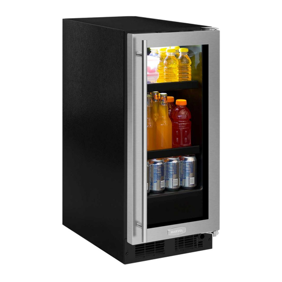
Page 21: Shelving Configurations
SHELVING CONFIGURATIONS Loading Tips and Suggestions Beverage Refrigerator: Your appliance is equipped with a cantilever shelf system 24" (61 cm) Wide Models: which provides maximum adjust ability and customizing of Shown with a glass door. Figure 27. the shelving arrangements listed below. (1) half width flat glass can- tilever shelf. - Page 22 SHELVING CONFIGURATIONS Refrigerator: 24" (61 cm) Wide Models: Shown with a solid door with door racks. Figure 30. (1) half width flat glass cantilever shelf. (See Figure 33). (1) frame and slumped glass cantilever shelf. Wine shelf (1) frame and flat underneath glass glass crisper cover.
- Page 23 SHELVING CONFIGURATIONS To Add or Remove a Shelf CAUTION Remove stored product from the shelf. Do not try to remove a loaded shelf from the appliance. Grasp the shelf front with both hands, rotate the front upward and lift out. (See Figure Make sure your cantilever shelf is secure on the shelf sup- 36b).
-
Page 24: Care And Cleaning
CARE AND CLEANING AND ENERGY SAVING TIPS The following suggestions will minimize the Front Grille cost of operating your refrigeration appliance. Be sure that nothing obstructs the required air flow open- ings in front of the cabinet. At least once or twice a year, brush or vacuum lint and dirt from the front grille area (see 1. -
Page 25: Door Alignment
If the product is within the first year warranty period models: please contact your dealer or call AGA MARVEL Cus- The door should be parallel to the sides and top of the ap- tomer Service at 800.223.3900 for directions on how to pliance. -
Page 26: Troubleshooting
TROUBLESHOOTING Before You Call for Service WARNING If the appliance appears to be malfunctioning, read through this manual first. If the problem persists, check the trouble- shooting guide below. Locate the problem in the guide and Electrocution Hazard refer to the cause and its remedy before calling for service. •... -
Page 27: Household Product Warranty
Limited One Year Parts and Labor Warranty Not Supplied or Designated by AGA MARVEL AGA MARVEL warrants that it will supply all necessary The above warranties also do not apply if: parts and labor to repair or replace in the end user’s home or office, any component which proves to be defective •... - Page 28 www.agamarvel.com 1260 E. VanDeinse St. Greenville MI 48838 800.223.3900 41013316-EN Rev F All specifications and product designs subject to change without notice. Such revisions do not entitle 11/5/14 the buyer to corresponding changes, improvements, additions, replacements or compensation for previously purchased products.
Need help?
Do you have a question about the ML15BC and is the answer not in the manual?
Questions and answers