Table of Contents
Advertisement
Quick Links
Advertisement
Table of Contents

Related Manuals for BIRD 424-86A-03


Summary of Contents for BIRD 424-86A-03
- Page 1 OU'RE EARD, OUD AND LEAR. Installation and Operation Manual for AutoQuad Tower-Top Amplifier System Model 424-86A-03 and 424-86A-03-48 Manual Part Number 7-9322-5 8625 Industrial Parkway, Angola, NY 14006 Tel: 716-549-4700 Fax: 716-549-4772 sales@birdrf.com www.bird-technologies.com...
- Page 2 Product part numbering in photographs and drawings is accurate at time of printing. Part number labels on TX RX products supersede part numbers given within this manual. Information is subject to change without notice. Bird Technologies Group TX RX Systems Inc.
- Page 3 First Printing: March 2003 Version Number Version Date 03/04/03 08/01/03 04/26/04 02/15/06 08/09/06 Symbols Commonly Used WARNING ESD Elecrostatic Discharge CAUTION or ATTENTION Hot Surface High Voltage Electrical Shock Hazard NOTE Use Safety Glasses Important Information Bird Technologies Group TX RX Systems Inc.
-
Page 5: Table Of Contents
Table of Contents General Description .................... 1 Unpacking ......................4 Pre-Installation Checkout ................... 4 Mechanical Inspection ..................4 Pre-installation Static Sensitivity Testing ............4 Installation......................6 Interference and Intermodulation Considerations ..........6 Installing the System ..................8 Installing the Tower-Top Box ................8 Installing the Multicoupling Amplifier .............. - Page 6 Figures and Tables Figure 1: Front view of the tower-top box ............1 Figure 2A: Top view of the multicoupler unit (MCA) ..........2 Figure 2B: Front view of the MCA ............... 2 Figure 2C: Back view of the MCA ................ 2 Figure 3: Test equipment interconnection for “bench testing”...
-
Page 7: General Description
GENERAL DESCRIPTION ary quad-amplifier if conditions indicate a primary malfunction. If the secondary quad-amplifier mal- The AutoQuad Tower-Top Amplifier System pro- functions, operation switches to whichever quad- vides the highest degree of reliability available in a amplifier is still providing some gain due to opera- Tower-Top Amplifier (TTA) system. -
Page 8: Figure 2A: Top View Of The Multicoupler Unit (Mca)
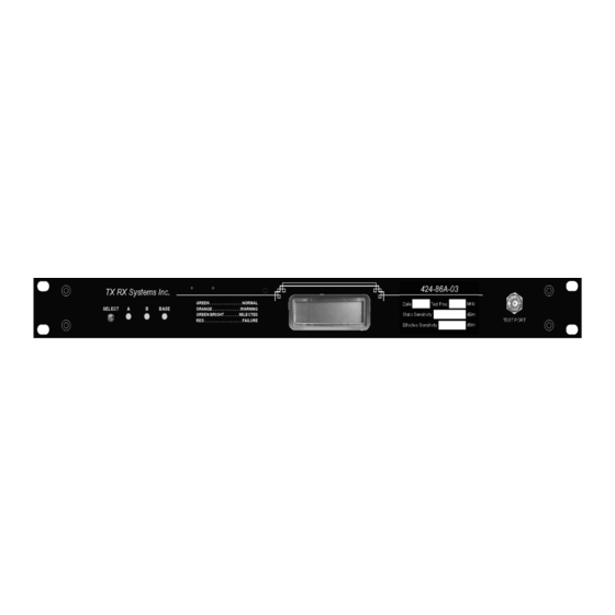
3-18171 4-Way 8-Way 8-Way Power Divider Power Divider Power Divider Figure 2A: Top view of the Multicoupling Amplifier (MCA). NOTE: 48 VDC converter used in model 424-86A-03-48. NOTE Display Contrast Enter Button Scroll Button Tool required for button presses, Adjustment... - Page 9 “A” and amplifier “B,” feedback on the system’s operating status. Also, input and output switching circuitry, a tri-mode test model 424-86A-03 houses a power supply, model switch assembly and PolyPhaser surge suppres- 424-86A-03-48 houses a 48 VDC converter. The sors with DC bias-tap (see Figure 1).
-
Page 10: Unpacking
UNPACKING release the door. Make sure that all the N and TNC connectors are tight. In addition, it is advisable to Each major component of the TTA system is indi- check the tightness of the hold-down screws for the vidually packaged and shipped via motor freight or various assemblies to insure nothing loosened dur- UPS. - Page 11 Tower Top Amplifier System Test Data Sheet (table 4) System Model No. System Serial No. Date / Initial Date / Initial Date / Initial Test Cable length/ Test Cable length/ Test Cable length/ type type type RX Serial # RX Serial # RX Serial # RX Frequency RX Frequency...
-
Page 12: Installation
8-Way Power Dividers on Expansion Deck Test Main Port Transmission Line Line Main Test Antenna Transmission Port Figure 4: Cable connections for system components. NOTE: 48 VDC converter used in model 424-86A-03-48. TX RX Systems Inc. Manual 7-9322-5 08/09/06 Page 6... -
Page 13: Figure 5: System Installation Guidelines
DESIGN STANDARDS Mainline grounded at top, base, shelter entrance and every 75 feet Tower Top Amplifier All external cable connections weatherproofed Hoisting grips used every 200 feet per mainline 1/2" LDF 10 foot jumper cable from each antenna to its mainline and tower-top amplifier Test Port 1/2"... -
Page 14: Installing The System
because the receiver multicoupler, which is incor- porated in the MCA, serves this purpose. Mounting Tabs Installing the System Figure 4 illustrates the cable connection points for both the tower-top box and the MCA. Installation of the AutoQuad TTA system should follow the design standards listed in Figure 5. -
Page 15: Installing The Multicoupling Amplifier
“ + and - ” at the back of the MCA. using all mounting tabs. The box must be mounted with the connectors and 4) For model 424-86A-03, plug the MCA into a moisture relief valve facing down- suitable AC outlet. Connect the 24 VDC backup ward to prevent water entry. -
Page 16: About Reserve Gain And Attenuation
CAUTION: On units without the volt- reduction of reserve gain may only be necessary age limiter (par t# 3- 20015) the when the main transmission line loss is low; that is, backup voltage can not exceed 26.7 when line loss does not reduce the TTA gain volts. -
Page 17: Setting Reserve Attenuation
SETTING RESERVE ATTENUATION About Multicoupler Gain and Attenuation Reserve attenuation is adjustable from 0 to 15 dB Multicoupler gain (referred to as BASE gain) is also in 0.5 dB increments. To adjust the reserve attenu- adjusted after installation to obtain best system ation perform the following steps. -
Page 18: Installed Sensitivity Test
Preselector System fully installed Sampler Main and base gain set Output Port Input Test cable temporarily connected to antenna port and Signal Generator Input Switch Installed sensitivity determined - Pre-installed sensitivity = line loss Output Signal Generator Switch FRX MHz Main Test 3 KHz dev... -
Page 19: Tri-Mode Test Port
Test cable loss = (-126) dBm - (-119) dBm = -7 dB Mode 2 (Antenna Sweep) connects the test cable directly to the antenna. This mode facilitates The test cable loss subtracts from the measured sweeping the transmission line and antenna with sensitivity at ground level (static sensitivity) to yield minimal disruption to the system. -
Page 20: Test Port Sensitivity With Dummy Load (Mode 1)
“>” symbol next to the MODE menu change the used for diagnostic connections has relatively high signal loss per foot at 800 MHz and higher. If differ- mode using the enter button. For additional testing while in modes 0 or 1 the active amplifier ent cable lengths are used when making tests, it in the TTA can be changed also. -
Page 21: Figure 12: Testing Output Spectrum
Antenna Test Port Daughter Board Spectrum Analyzer Figure 12: Testing the output spectrum of the TTA system. Preamp Spectrum Analysis Maximum Signal Level Mask Receive Band -35 dBm to -45 dBm Transmit Band Less than -55 dBm Remaining Spectrum Less than -75 dBm Receive Band Transmit Band Frequency (MHz) -
Page 22: Spectrum Analysis
The equipment is connected as Intermodulation type interference. shown in Figure 14. Using a Site analyzer, such as the Bird Electronics Model SA-6000EX, mainte- Preselector Bird ® Electronic... -
Page 23: Routine Operation
For model 424-86A-03, plug in the MCA’s AC cord. problem develops within the primary. For model 424-86A-03-48, connect the MCA to a 48 VDC source. -
Page 24: Figure 15: Block Diagram Of Tower Box
Figure 15: Block diagram of the tower-top box. TX RX Systems Inc. Manual 7-9322-5 08/09/06 Page 18... -
Page 25: Figure 16: Block Diagram Of The Mca
Figure 16: Block diagram of multicoupling amplifier. TX RX Systems Inc. Manual 7-9322-5 08/09/06 Page 19... -
Page 26: System Status Monitoring
SYSTEM STATUS MONITORING Amplifier Displayed Value The system continuously monitors the current being Amp A (part# 3-18941) 285-435 drawn by all three amplifiers, and reveals the status Amp A (part# 3-19285) 450-600 of the amplifiers in three ways: LCD Display, status- Amp B (part # 3-18941) 285-435 indicator LEDs and Form-C contacts (“screw termi-... -
Page 27: Alarms
DC 3) Logic circuit failure. short on the transmission or test port lines. 4) AC line fuse (model 424-86A-03). TX RX Systems Inc. Manual 7-9322-5 08/09/06... -
Page 28: Logic Circuit Failure
Loss of Sensitivity (Intermittent / Continuous) Individual Receive Channel(s) affected All Receive Channels affected Intermittent Continuous Intermittent Continuous Measure Effective Sensitivity Measure Effective Sensitivity Measure Effective Sensitivity Measure Effective Sensitivity Small to moderate loss of sensi- Small to severe loss of sensitiv- Small to moderate loss of sensi- Small to severe loss of sensitiv- tivity... -
Page 29: Optional Preselector Filters
OPTIONAL PRESELECTOR FILTERS Because the tower-top box is equipped with a WARNING steep-skirted bandpass filter, most problems will be the result of strong signals within this filter’s pass- band. However, if strong nearby transmitters which are outside the receive band exceed the -55 dBm Whenever a tower-top box, the base control unit, or level they may contribute to intermodulation or car- any amplifier assembly is swapped out of the sys-... -
Page 30: Multicoupling Amplifier
N OT E : T h e t ow e r - t o p a m p l i f i e r 5) Next, the current alarm trip point must be NOTE assemblies are “hot” switchable, adjusted. To adjust the trip point press and hold m e a n i n g t h e a m p l i f i e r c a n b e down the “ENTER”... -
Page 31: Options
3) Remove the two hold-down screws, which are Narrowband Preselector Filter accessible from the bottom of the base plate, This option is designed to be added to the RF sig- and remove the defective amplifier assembly. nal path just ahead of the input to the “base” ampli- fier on the MCA. - Page 32 2.818 0.331 0.11 3.02 9.12 0.589 0.347 1.698 2.884 0.327 0.107 3.055 9.333 0.582 0.339 1.718 2.951 0.324 0.105 3.09 9.55 0.575 0.331 1.738 3.02 0.32 0.102 3.126 9.772 0.569 0.324 1.758 3.09 Bird Technologies Group TX RX Systems Inc.
- Page 33 However, allowing for these variances, these graphs should prove to be a useful reference. INSERTION LOSS (dB) OUTPUT POWER (Watts) FOR LOWER POWER LEVELS DIVIDE BOTH SCALES BY 10 (5 TO 50 WATTS) Bird Technologies Group TX RX Systems Inc.
- Page 34 VSWR 1.1:1 1.15:1 1.2:1 1.25:1 1.3:1 1.4:1 1.5:1 1.6:1 1.8:1 2.0:1 2.5:1 3.0:1 10 8.0 6.0 1.0 0.8 0.6 REFLECTED POWER (Watts) FOR OTHER POWER LEVELS MULTIPLY BOTH SCALES BY THE SAME MULTIPLIER Bird Technologies Group TX RX Systems Inc.
- Page 35 Free Space Loss Distance (miles) 1920 Free Space Loss (dB) Free space loss = 36.6 + 20log D + 20log F Where D = distance in miles and F = frequency in MHz Bird Technologies Group TX RX Systems Inc.
- Page 36 8625 Industrial Parkway, Angola, NY 14006 Tel: 716-549-4700 Fax: 716-549-4772 sales@birdrf.com www.bird-technologies.com...
Need help?
Do you have a question about the 424-86A-03 and is the answer not in the manual?
Questions and answers