Table of Contents
Advertisement
Quick Links
Advertisement
Table of Contents

Subscribe to Our Youtube Channel
Related Manuals for Arcon WORKHORSE 300MS 010310-series


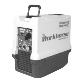
Summary of Contents for Arcon WORKHORSE 300MS 010310-series
- Page 1 WORKHORSE 300MS MIG / Stick P/N 010310 240V, 400V, 480V, 575V, Dual Voltage 240/480V OPERATING MANUAL REVISED MARCH 2009 2203 Northwood Drive, Unit #10, Salisbury Md 21801, USA Tel: 410.572.6000 Toll Free: 888 512.7266 Fax: 410.572.6027 sales@arconweld.com www.arconweld.com...
-
Page 2: Declaration Of Conformity
Declaration of Conformity Manufacturer's Name: ARCON Welding Equipment, LLC Manufacturer's Address: 2203 Northwood Drive, Building 10 Salisbury, Maryland 21801 USA Declares that the product: Product Name: Workhorse 300MS Model Numbers 010310-xxx Conforms to the following standards: Underwriters Laboratories Standard UL551... -
Page 3: Table Of Contents
Table of Contents GENERAL INFORMATION User Responsibility Manufacturer’s Limited Product Warranty Safety Standards Seahorse Information Page 1. SAFETY 1.1 Safety Symbols 1.2 Safety Precautions 1.3 Electric Shock 1.4 Arc Rays and Eye Protection 1.5 Fumes and Oxygen Depletion 1.6 Welding Sparks 1.7 Electric and Magnetic Fields 1.8 Protect Yourself and Others 2. - Page 4 4.4 Welding Operation 4.4.1 Recommendations for E70S- 3 Spray Transfer 4.4.2 Short Circuit Transfer/Short Arc 4.4.3 Stick Welding 4.5 Dual Voltage Changeover 5. MAINTENANCE 6. ELECTICAL SPECIFICATIONS AND DIAGRAMS General Information Product Specifications Block Diagram of The Inverter Main Control Board Main Circuit Diagram Front Panel Rear Panel...
-
Page 5: General Information
ARCON’s applicable hourly labor rate and current replacement part prices. MANUFACTURER’S LIMITED PRODUCT WARRANTY ARCON Welding Equipment’s only warranty is that goods being sold will be free from defects in materials and workmanship. This express warranty is in lieu of any other warranties, either expressed or implied, and whether statutory or otherwise, including any implied warranty of merchantability or fitness for a particular purpose. - Page 6 The Seahorse process used in this machine was developed and tested on oilrigs in the North Sea decades ago. This protection enhances reliability, prolongs component life and adds value to all of ARCON’s rugged line of portable welding power sources. Listed below are some of the steps ARCON...
-
Page 7: Safety
1. SAFETY Safety is eveyone’s responsibility. ARCON designs every machine with safety in mind, and a safe work environment depends largely on you. Do not install, operate, or repair this equipment without carefully reading this manual and observing all of the safety precautions mentioned. -
Page 8: Electric Shock
ELECTRIC SHOCK Precautionary measures must be taken to provide maximum protection against electrical shock. Electric shock can injure or Kill WARNING 1. Do not touch live or energized electrical parts or store metallic objects near power. 2. Ground the work or metal to be welded to a good electrical (earth) ground. 3. -
Page 9: Fumes And Oxygen Depletion
FUMES and OXYGEN DEPLETION Only weld in areas or rooms where adequate ventilation of weld gases is possible, and where there are not fire, smoke or explosion hazards. When working in a confined space always have trained support personnel nearby. Welding fumes and gases can displace air and lower the oxygen level causing injury or death. -
Page 10: Protect Yourself And Others
PROTECT YOURSELF AND OTHERS! Some welding, cutting, and gouging processes are noisy and require ear protection. The arc, like the sun, emits ultraviolet (UV) and other radiation and may injure skin and eyes. Hot metal can cause burns. Training in the proper use of welding processes and equipment is essential to prevent accidents. -
Page 11: Product Specifications
2.2 PRODUCT SPECIFICATIONS Product Specifications for 300MS Rated Welding Open Input Amperes at Physical Weight Welding Primary Current Range Circuit Rated Load Output Efficiency Dimensions (Amps) Amps Voltage 50/60 Hz Input @ Duty Cycle Ship Height: 17.9" Three 400A@29% Range 1 80 Max 14.9 79.60%... -
Page 12: Selecting A Location
damage which may have occurred in transit. After removing the components from the shipping container(s), check the container for any loose parts. Remove all packing materials. Visually check air passages of power source for any packing materials that may obstruct airflow through the welder. -
Page 13: Fuses
3.5 Fuses It is recommended that input fuse sizes be in accordance with the table below: Input Voltage Welder input Recommended Fuse Maximum Amperage Capacity 240 V 3-Phase 240 V Single-phase 400 V 480 V 575 V Table 3.0 3.6 O UTPUT CONNECTIONS Female Dinse type (manufactured by DIX) are the standard output connectors. - Page 14 The schematic diagram to the right illustrates how the typical wire feeder should be connected to the remote plug for either 24 Volts* or 115 Volts, depending on the power requirement for the wire feeder. FIGURES FOR SECTION 3.7...
-
Page 15: Remote Pin Configuration
3.8 Pin configuration for the MIGweld 300MS power source: A 24VAC* 5A Supply B 24VAC* Remote Contactor C +15V DC to Remote Current Control D Remote Current Common (PCB Ground) E Remote Current Level F Current Feedback, 1V DC per 100A output G 24VAC / 115VAC Common H Voltage Feedback, 1V DC per 10V output 115VAC 5A Supply... -
Page 16: Operation
4. OPERATION WARNING! LEASE READ HAPTER REGARDING AFETY 4.1 General Description The Workhorse power source combines time-proven technology with modern technology to provide high-quality performance. The digitally controlled SCR type inverter is very reliable in welding applications and able to deliver up to 400 Amps of power (@29% Duty Cycle). 4.2 Design Features The Workhorse power source is designed to be portable and easily transported to provide many benefits. -
Page 17: Arc Force Control
While operating in GMAW-S (short circuit) mode, the weld power control will set the average power supplied to the weld. Selecting an operating point requires a balanced selection of gas, wire diameter, proper wire feed speed, and weld power. The weld puddle control should remain at the mid-point during the initial adjustment until a suitable combination of weld power and wire feed speed is obtained. -
Page 18: Process Control Selector
The higher setting will create a more stable arc for electrodes that easily become unstable, such as cellulose (5P). If you do not know the optimal setting for the electrode you are using, start at the highest setting and lower it until the arc just begins to become unstable. -
Page 19: Voltage Changeover (Dual Voltage Models)
4.3.11 Output Terminals Select output cable size based on Table 4 (following page). Duty cycle(%) Current (A) Length (Ft) Cable Size (AWG) 1 - 50 1 – 150 150 - 200 TABLE 4 4.3.12 Voltage Changeover The Voltage Changeover opening is located on the rear panel, to the right of the input power cable. -
Page 20: Welding Operation
4.4 Welding Operation 4.4.1. Recommendations for E70S-3 Spray Transfer Wire Range 2 Current Wire Feed Voltage Diameter Power Speed (inches) Setting (IPM) .035 50-100 180-290 350-450 25-28 .045 60-100 200-300 250-450 25-28 *Using 98/2 AR0O2 shielding gas. The recommended power and range settings represent the manufacturer’s best estimate and are intended only as guidelines for the Workhorse 300MS. -
Page 21: Maintenance
Do not permit untrained persons to inspect, clean, or repair The Workhorse 300MS. Please call the factory for the location of the Authorized ARCON Service Center nearest you. Since there are no moving parts other than the fan in the power source, basic preventive maintenance only involves keeping the welder clean and free from metallic dust. -
Page 22: General Information
6. ELECTRICAL SPECIFICATIONS & DIAGRAMS 6.1 General Information Circuit breaker The 3 phase elecric input power is connected to circuit breaker (K). When the welder is used for 240 V single phase, the brown conductor is not connected. When the correct phases are connected, the fan will start and run for a few minutes and then stop. -
Page 23: Product Specifications
MIGWELD 300MS 6.2 Product Specifications Input Amperes at Rated Welding Open Weight Welding Current Eff. (Amps) Primary Circuit Rated Load Output Dimensions Input Range Voltage 50/60 Hz Ship 480 400 575 Three 300 amps Height: 17.9" Phase @ 32V Range 1 14.9 12.05 79.60% (45.5 cm) 60% Duty... -
Page 24: Block Diagram Of The Inverter
6.3 Block Diagram of The Inverter The Principle Of The Inverter Design The inverter function is perhaps easiest understood using the simplified block diagram below. AC INPUT MAIN RECTIFIER INVERTER TRANSFORMER RECTIFIER CONTROL BOARD OUTPUT FILTER TIME/CURRENT WELDING AUXILIARY CONTROLLED OUTPUT TRANSFORMER FIGURE 6... -
Page 25: Main Control Board
(See main circuit diagram Figure 6.5 overleaf) 6.4 Main Control Board The auxiliary transformer T1 powers the main control board. The AMP male connectors J10 to J14 controls the firing of the SCRs. J1 is connected to the potentiometer adjusting the weld power level. J2 is the remote connector. -
Page 26: Main Circuit Diagram
6.5 MAIN CIRCUIT DIAGRAM... -
Page 27: Front Panel
6.6 FRONT PANEL WITH PART NUMBER REFERENCE... -
Page 28: Rear Panel
6.7 REAR PANEL DRAWING WITH PART NUMBER REFERENCE... -
Page 29: Chassis Plate Drawing 1 With Part Number Reference
6.8 ASSEMBLY DRAWING 1 WITH PART NUMBER REFERENCE... -
Page 30: Chassis Plate Drawing 2 With Part Number Reference
6.9 ASSEMBLY DRAWING 2 WITH PART NUMBER REFERENCE... -
Page 31: Inductor Plate Drawing With Part Number Reference
6.10 INDUCTOR PLATE DRAWING WITH PART NUMBER REFERENCE... -
Page 32: Replacement Parts
7.1 REPLACEMENT PARTS NUMBER DESCRIPTION NOTE 010401-001 CASE BOTTOM, Dark Gray 010410-001 CASE TOP w/ HANDLES 010420-010 REAR PANEL ASSY, METAL MIG 010420-011 REAR PANEL ASSY, DUAL VOLT MIG 010420-013 REAR PANEL ASSY, METAL 575V MIG 010420-112 REAR PANEL ASSY, MIG WARHORSE 010440-002 POWER CABLE, 10 AWG, 12.5FT 010440-004... - Page 33 011271-102 AUXILIARY TRANSFORMER, 480V MIG 011271-103 AUXILIARY TRANSFORMER, 240V MIG 011271-104 AUXILIARY TRANSFORMER, DUALV MIG 011271-105 AULILIARY TRANSFORMER, 575V MIG 011300-001 SHUNT, CALIBRATED 011400-001 OUTPUT DIODE & HEATSINK ASSY 011502-001 CAPACITOR PCB ASSY, 400V MIG 011502-002 CAPACITOR PCB ASSY, 480V MIG 011502-003 CAPACITOR PCB ASSY, 240V MIG 011502-004...
-
Page 34: Accessories
017001-002 KNOB, LARGE 017102-001 OUTPUT CAPACITOR CLAMP 017102-003 INPUT CAPACITOR CLAMP w/ PTC PCB 017110-001 MAIN TRANSFORMER MOUNTING BRKT 017200-001 LENS, RED, FOR DIGITAL METER 017601-001 RF SUPPRESSOR COIL FOR CE 018001-002 POWER CABLE, 10AWG CE 018001-005 POWER CABLE, 12AWG 5-COND 018001-008 POWER CABLE, 10AWG USA 018401-001... - Page 35 WA310-011 REMOTE CABLE, MIG, 6’ WA310-012 REMOTE CABLE, MIG, 10’ WA310-013 REMOTE CABLE, MIG, 15’ WA310-014 REMOTE CABLE, MIG, 25’ WA310-015 REMOTE CABLE, MIG, 50’ WA310-016 REMOTE CABLE, MIG, 75’ WA310-021 WORK CLAMP w/ 12’ 1/0 CABLE WA310-022 WORK CLAMP w/ 15’ 2/0 CABLE WA310-023 WORK CLAMP w/ 35’...
-
Page 36: Troubleshooting Guide
8. TROUBLE SHOOTING GUIDE WARNING – PLEASE OBSERVE ALL SAFETY PRECAUTIONS TROUBLE PROBABLE CAUSE REMEDY Cooling fan does not start Incorrect input wiring. Switch the machine to ”Off”. within the first few seconds Check input wiring. For single after the machine is switched phase wiring, use the two black wires and drop the brown or red wire.
Need help?
Do you have a question about the WORKHORSE 300MS 010310-series and is the answer not in the manual?
Questions and answers