
Related Manuals for Arcon IRONHORSE 300S


Summary of Contents for Arcon IRONHORSE 300S
- Page 1 IRONHORSE 300S 700V DC P/N 010350-006 OPERATING MANUAL 2300 Northwood Drive Salisbury MD 21801 Tel: 410 572.6000 Fax: 410 572.6027 www.arconweld.com sales@arconweld.com...
-
Page 2: Table Of Contents
Table of Contents User Responsibility General Information Warranty Introduction to Ironhorse Stickweld 300S 1. Safety Precautions IRONHORSE SET UP CHECKLIST 1.1 ELECTRIC SHOCK can kill! 1.2 ARC RAYS can burn! 1.3 FUMES AND GASES can be dangerous! 1.4 WELDING SPARKS can cause fire or explosion! 1.5 ELECTRIC AND MAGNETIC FIELDS may be dangerous! 1.6 PROTECT YOURSELF AND OTHERS! 2. -
Page 3: User Responsibility
ARCON Welding LLC will be charged based on Arcon’s applicable hourly labor rate and cost of spare parts. -
Page 4: General Information
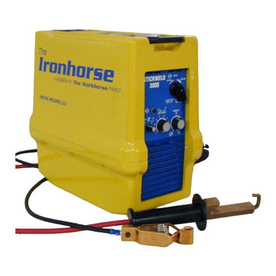
45 days from the date of shipment to the rental company, whichever is earlier. Introduction to The Ironhorse 300S 700V DC The Ironhorse 300 700V DC is a portable welder using an inverter type power supply to generate the output power. - Page 5 Ironhorse Setup Checklist NEVER WELD ON THE LIVE THIRD RAIL! These are basic instructions for installing cables and supplying power to The Ironhorse welding power source. The individual connecting cables for welding should be certified (by the employer) and be familiar with the fundamentals of welding and electricity. All precautionary measures must be taken to provide maximum protection against electrical shock.
-
Page 6: Safety Precautions
1. Safety Precautions 1.1 ELECTRIC SHOCK Precautionary measures must be taken to provide maximum protection against electrical shock. 1. Do not touch live electrical parts. 2. Turn OFF welding power source before servicing unless the procedure specifically requires an energized unit. 3. - Page 7 4 When working in a confined space always have trained support personnel nearby. Welding fumes and gases can displace air and lower the oxygen level causing injury or death. Be sure the breathing air is safe. 5 Do not weld in locations near degreasing, cleaning, or spraying operations. The heat and rays of the arcs can react with vapors to form highly toxic and irritating gases.
-
Page 8: Protect Yourself And Others
1.6 PROTECT YOURSELF AND OTHERS! Some welding, cutting, and gouging processes are noisy and require ear protection. The arc, like the sun, emits ultraviolet (UV) and other radiation and may injure skin and eyes. Hot metal can cause burns. Training in the proper use of welding processes and equipment is essential to prevent accidents. -
Page 9: Introduction And Installation
2. Introduction and Installation • WARNING! • Only qualified personnel should perform this installation. • Turn the input power off at the disconnect switch or fuse box before working on The Ironhorse. • Do not touch electrically hot parts. This section provides detailed instructions for the proper installation of The Ironhorse. It is recommended that these instructions be followed carefully to allow for the best possible operating environment. -
Page 10: Input Connections
2.2 INPUT CONNECTIONS 2.2.1 C ONNECTING INPUT POWER The primary cable supplied with the power source has 2 conductors, which split into two 5ft long single conductors. The positive has red bands and will be connected to a third rail clamp, or a catenary pole. The negative will be connected to an alligator clamp. 2.3 O UTPUT CONNECTIONS The standard supplied output connector types are female Dinse (DIX). -
Page 11: Operation
3. OPERATION WARNING! LEASE READ HAPTER REGARDING AFETY 3.1 Controls and Settings 3.1.1 Circuit Breaker (Power On/Off) The Circuit Breaker is located on the control panel at the rear of the machine. Move the switch lever up to the ON position to start the machine. This also activates the Thermostat- controlled Cooling Fan for approximately 6 minutes indicating that correct power connections have been applied. -
Page 12: Power On Indicator
3.1.6 Process Control Selector The Process control selector has three settings, Stick, TIG and Stick. The Ironhorse 700VDC has the same characteristics for both Stick settings. The pipe-welding version has a cellulose characteristic, allowing 1 inch of arc length when this method of whipping is used. The TIG position allows Lift Start, which allows contact between material and electrode with no damage to the electrode. -
Page 13: Range Switch
3.1.10 Output Terminals Select output cable size based on table 3.0 below. Duty cycle(%) Current (A) Length (Ft) Cable Size (AWG) 1 – 50 1 – 150 150 – 200 TABLE 3.0 RANGE SWITCH POWER ON 3.1.3 INDICATOR 3.1.7 CIRCUIT BREAKER (POWER ON/OFF) PROCESS SWITCH 3.1.1... -
Page 14: Welding Operation
3.2 Welding Operation 1. After both the third rail clamp (or catenary pole clamp) and the ground clamp are connected, close the circuit breaker on the welder. 2. The Power-On light on the front panel will be lit. 3. Put the Mode Selector in the ‘Stick’ position. The welding output will be energized and the electrode holder will become “electrically-hot”. -
Page 15: Maintenance
Please note: Opening up the case voids the Warranty. Maintenance or repair should only be performed by an authorized ARCON Service Center, or by the facvtory. Do not permit untrained persons to inspect, clean, or repair The Ironhorse. Please call the factory for the location of the Authorized ARCON Service center nearest you. -
Page 16: Electrical Specifications
5. Electrical Specifications 5.1 Product Specifications THE IRONHORSE Stickweld 300 S 700 V DC Product Specifications Input Amperes at Rated Welding Open Weight, Including Welding cable Current Eff. (Amps) Primary Circuit Rated Load Dimensions Output Input 60% Duty Range Voltage Cycle Ship 600V... -
Page 17: Theory Of Operation
5.2 Theory of Operations The inverter function is perhaps easiest understood using the simplified circuit diagram below. DC INPUT MAIN INVERTER TRANSFORMER AUXILIARY CONVERTER RECTIFIER CONTROL BOARD OUTPUT AUXILIARY FILTER TRANSFORMER TEMPERATURE WELDING CONTROLLED OUTPUT FIGURE 5.2... -
Page 19: Front Panel
5.4 Front Panel... -
Page 20: Rear Panel
5.5 Rear Panel... -
Page 21: Bottom Chassis Drawing
5.6.1 Bottom Chassis Drawing with Part Number Reference... -
Page 22: Top Chassis Drawing
5.6.2 Top Chassis Drawing with Part Number Reference... -
Page 23: Inductor Plate Drawing
5.6.3 Inductor Plate Drawing with Part Number Reference... -
Page 24: Replacement Parts List
IRONHORSE REPLACEMENT PARTS LIST PART NUMBER DESCRIPTION REF# 011260-003 TRANSFORMER, MAIN, w/PTC 010440-003 ASSY, 8AWG PWR CABLE -Y-INPUT 010490-001 CHASSIS, MAIN 010511-001 REAR PANEL, UPPER - BLUE 010513-001 PANEL, LOWER REAR 010551-051 PANEL, FRONT - BARE (PRINTED) 010553-001 LAMP, INDICATOR - YELLOW 017001-002 KNOB, FOR CURRENT/ARC FORCE CONTROL 017001-001... - Page 25 010560-002 LOUVER, FRONT 010512-002 LOUVER, REAR 016202-001 RESISTOR, SURGE, 0.15 OHM 016330-001 CIRCUIT BREAKER 018401-001 BRACKET, CIRCUIT BREAKER 016331-001 SPACER, CIRCUIT BREAKER 019600-001 GAS VALVE ASSY 016611-001 DIODE, AVALANCHE, CATHODE ON STUD END 016610-001 DIODE, AVALANCHE, ANODE ON STUD END 016627-020 RESISTOR, 12 OHM, FOR OUTPUT BOARD 017102-001...
Need help?
Do you have a question about the IRONHORSE 300S and is the answer not in the manual?
Questions and answers