Table of Contents
Advertisement
Quick Links
SERVICE MANUAL
Ver 1.3 2001. 02
Ver 1.0 2001. 01
SPECIFICATIONS
Frequency range
FM : 87.5 – 108 MHz
AM : 530 – 1,605 kHz
Speaker
Approx. 4.5 cm (1
/
inches) dia., 8 ohms
3
4
Power output
60 mW (Using the built-in rechargeable
battery)
90 mW (Using size AA (R6) dry batteries, not
supplied)
Output
v jack (minijack)
Power requirements
Built-in nickel-cadmium (2.4 V, 300 mAh,
Ni-Cd) battery or 3 V DC, two size AA (R6) dry
batteries
Dimensions
Approx. 163 × 80 × 55 mm (w/h/d)
× 3
× 2
(6
1
/
1
/
1
/
in)
2
4
4
Mass
Approx. 320 g (11.3 oz)
Approx. 355 g (12.6 oz) incl. batteries and
projecting parts
Supplied accessory
Hand strap (1)
Design and specifications are subject to change
without notice.
Sony Corporation
9-925-744-13
2001B0400-1
Audio Entertainment Group
© 2001. 2
General Engineering Dept.
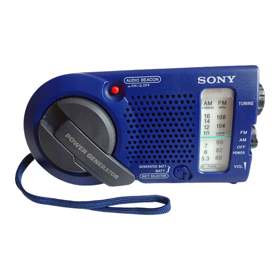
ICF-B200
FEATURES
Self-powered emergency radio
• You may use the radio right away by turning the
handle of the power generator, which charges the
built-in nickel-cadmium (Ni-Cd) rechargeable
battery. —Hand generating function
• You may also use size AA (R6) dry batteries (not
supplied).
• Audio Beacon that alerts the surroundings.
• Useful dial light when tuning in the dark.
• Water-resistant for all weather operation*.
* Do not emmerse in water
This product is designed to be water-resistant,
but should not be emmersed in water or come in
continuous contact with water.
Before installing the batteries, be sure to wipe off
drops of water on the unit.
US Model
Canadian Model
AEP Model
FM/AM RADIO
1
Advertisement
Table of Contents

Related Manuals for Sony ICF-B200


Summary of Contents for Sony ICF-B200
- Page 1 ICF-B200 SERVICE MANUAL US Model Canadian Model Ver 1.3 2001. 02 Ver 1.0 2001. 01 AEP Model SPECIFICATIONS FEATURES Frequency range Self-powered emergency radio FM : 87.5 – 108 MHz • You may use the radio right away by turning the AM : 530 –...
-
Page 2: Table Of Contents
HOW TO CHANGE THE CERAMIC FILTERS TABLE OF CONTENTS This model is used two ceramic filters of CF1 and CF3. You must use same type of color marked ceramic filters in order to 1. GENERAL meet same specifications. Power Sources ................ 3 Therefore, the ceramic filter must change two pieces together since Playing the Radio .............. - Page 3 SECTION 1 GENERAL This section is extracted from instruction manual. – 3 –...
-
Page 4: Service Note
Be sure to perform the following work when the cabinet, telescopic antenna and knobs have been replaced in servicing : Apply SONY grease SGL-505 (7-662-010-04) to all around the rib of the cabinet (rear) with an applicator or other means. Also,... -
Page 5: Disassembly
SECTION 3 DISASSEMBLY Note : Follow the disassembly procedure in the numerical order given. 3-1. CABINET (REAR) ASSY 1 Open the battery case lid. 4 cabinet (rear) assy 3 tapping screws (bind 2x20) 2 tapping screws (bind 2x20) 3-2. MAIN BOARD ASSY 5 generator 4 PTP 3x10 3 PTP 3x10... -
Page 6: Main Board
3-3. MAIN BOARD Note : When installing, setting the pointer. 7 MAIN board 8 LED board 3 gear (midway) 5 lamp 1 retainer 2 tuning shaft 6 claws 4 dial scale 3-4. POINTER SETTING 2 gear (midway) Note : Align part A with the rack gear (VC) concave of the gear (VC). -
Page 7: Electrical Adjustments
SECTION 4 SECTION 5 ELECTRICAL ADJUSTMENTS DIAGRAMS • IC Block Diagrams AM IF ADJUSTMENT AM RF signal Adjust for a maximum reading on level meter. generator Put the lead-wire 455 kHz IC1 CXA1019S antanna close to the set. AM FREQUENCY COVERAGE 30 % amplitude ADJUSTMENT modulation by... -
Page 8: Printed Wiring Boards
ICF-B200 5-1. PRINTED WIRING BOARDS • Semiconductor Location Ref. No. Location F-11 Note: • X : parts extracted from the component side. • Y : parts extracted from the conductor side. W : indicates side identified with part number. •... -
Page 9: Schematic Diagram
ICF-B200 5-2. SCHEMATIC DIAGRAM • Refer to page 8 for IC Block Diagrams. TOTAL CURRENT FM : 6.0mA AM : 4.5mA BUZZER ON : 30mA LIGHT ON : 60mA Note: • All capacitors are in µF unless otherwise noted. pF: µµF 50 WV or •... -
Page 10: Exploded Views
Ver 1.3 2001. 02 Ver 1.3 2001. 02 SECTION 6 EXPLODED VIEWS 6-2. CABINET (FRONT) SECTION NOTE: • The mechanical parts with no reference • -XX and -X mean standardized parts, so • Accessories and packing materials and number in the exploded views are not supplied. they may have some difference from the hardware (# mark) list are given in •... -
Page 11: Electrical Parts List
CONNECTOR JACK SECTION 7 ELECTRICAL PARTS LIST MAIN NOTE: • Due to standardization, replacements in • Items marked “*” are not stocked since When indicating parts by reference the parts list may be different from the they are seldom required for routine service. number, please include the board. - Page 12 MAIN Ref. No. Part No. Description Remark Ref. No. Part No. Description Remark 1-164-346-11 CERAMIC CHIP < COIL > 1-163-038-00 CERAMIC CHIP 0.1uF 1-163-038-00 CERAMIC CHIP 0.1uF 1-501-732-12 ANTENNA, FERRITE-ROD (AM) 1-163-038-00 CERAMIC CHIP 0.1uF 1-416-503-11 COIL, AIR-CORE 1-163-038-00 CERAMIC CHIP 0.1uF 1-406-028-00 COIL, OSC (AM) 1-416-504-11 COIL, AIR-CORE...
- Page 13 Ver 1.3 2001. 02 MAIN VOLUME Ref. No. Part No. Description Remark < SWITCH > 1-570-433-11 SWITCH, SLIDE (POWER) 1-572-552-31 SWITCH, SLIDE (BATT SELECT) @ S4 1-771-239-11 SWITCH, PUSH (1 KEY) (AUDIO BEACON) @ S4 1-771-367-11 SWITCH, PUSH (1 KEY) (AUDIO BEACON) <...
- Page 14 ICF-B200 Ver 1.3 2001. 02 REVISION HISTORY Clicking the version allows you to jump to the revised page. Also, clicking the version at the upper right on the revised page allows you to jump to the next revised page. Ver.
Need help?
Do you have a question about the ICF-B200 and is the answer not in the manual?
Questions and answers