Advertisement
Table of Contents
- 1 Table of Contents
- 2 Major Component List
- 3 Wall Mounting Instructions
- 4 Fitting the System to a Goose Neck
- 5 Pcb Layout Diagram
- 6 How to Wire Your System
- 7 Relays and Inputs
- 8 Gsm Antenna
- 9 External Keypads
- 10 Simcard
- 11 Power
- 12 System Checks
- 13 Mkii ID
- 14 Rebooting the Mkii
- 15 Antenna Instalation Guidelines
- 16 Supervisor Codes
- Download this manual
Advertisement
Table of Contents

Related Manuals for Comb Communications MKII

Summary of Contents for Comb Communications MKII
- Page 1 Tel: 011 805 9098 www.comb-communications.com Fax: 011 805 0174...
-
Page 2: Table Of Contents
GSM ANTENNA EXTERNAL KEYPADS SIMCARD POWER SYSTEM CHECKS MKII ID REBOOTING THE MKII ANTENNA INSTALATION GUIDELINES SUPERVISOR CODES Thank you for purchasing an intercom system from Comb Communications, Please download your User manual and Complex setup forms, from our website; www.comb-communications.com... -
Page 3: Major Component List
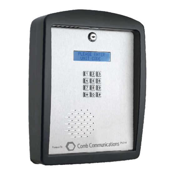
MAJOR COMPONENT LIST 1. Microphone 2. Plastic Enclosure 3. LED Lighting (Std White led) 4. Back Plate mounting holes 5. Main PCB 6. Battery (12v 0.8AH) 7. Transformer (15v 1amp) 8. Non Key alike barrel lock 9. Display (Blue writing white backlight) 10. -
Page 4: Wall Mounting Instructions
WALL MOUNTING INSTRUCTIONS Remove the front plate from the plastic enclosure. Unscrew the back plate from the enclosure. Screw the back plate to the wall. It is recommended that an 8mm nail in anchors be used. Bring 220v AC cabling in through the middle hole. Once the back plate is securely in place, screw the plastic enclosure to the back plate, feeding the cable though... -
Page 5: Pcb Layout Diagram
PCB LAYOUT DIAGRAM... -
Page 6: How To Wire Your System
HOW TO WIRE YOUR SYSTEM The MKII unit is supplied with some wiring in place. Before wiring the unit ensure that the Battery is unplugged and that the 220V mains supply is not powered. Refer to the PCB diagram. RELAYS and INPUTS (Defaults) Main Gate Trigger –... -
Page 7: Power
2. Connect the battery to the battery connector. SYSTEM CHECKS The MKII will now boot up and after about 1 minute is ready to operate. Make sure the installation is good by checking the following: GSM signal: type *#0002. The signal should be between 17 and 31. If not you may need a better GSM antenna or the GSM antenna wiring is faulty. -
Page 8: Supervisor Codes
The maximum GSM cable length should not exceed 10m, and should be kept as short as possible. Longer runs will require the use of higher gain antennae The GSM antenna can be extended from its standard length with a Comb- approved RF cable extensions. - Page 9 SUPPORT Please feel free to email our support department at support@comb- communications.com should you need any assistance in this regard Disclaimer There is no warranty for the contents hereof, to the extent permitted by applicable law. The document is provided "as is"...
Need help?
Do you have a question about the MKII and is the answer not in the manual?
Questions and answers