ASROCK H61M-VG4 User Manual
Hide thumbs
Also See for H61M-VG4:
- User manual (67 pages) ,
- Installation manual (54 pages) ,
- Quick installation manual (52 pages)

Related Manuals for ASROCK H61M-VG4


Summary of Contents for ASROCK H61M-VG4
-
Page 1: User Manual
H61M-PS4 / H61M-HG4 / H61M-VG4 / H61M-VS4 User Manual Version 1.0 Published May 2013 Copyright©2013 ASRock INC. All rights reserved. -
Page 2: Copyright Notice
ASRock. ASRock assumes no responsibility for any errors or omissions that may appear in this manual. With respect to the contents of this manual, ASRock does not provide warranty of any kind, either expressed or implied, including but not limited to the implied warran- ties or conditions of merchantability or itness for a particular purpose. -
Page 3: Table Of Contents
8 / 8 64-bit / 7 / 7 64-bit / Vista / Vista 64-bit Without RAID Functions . 30 2.11 ASRock XFast 555 ............. 31 2.11.1 ASRock XFast RAM ........... 32 2.11.2 ASRock XFast LAN ..........35 2.11.3 ASRock XFast USB ..........39... - Page 4 3 UEFI SETUP UTILITY .......... 41 3.1 Introduction ..............41 3.1.1 UEFI Menu Bar ............ 41 3.1.2 Navigation Keys ........... 42 3.2 Main Screen ..............42 3.3 OC Tweaker Screen ............44 3.4 Advanced Screen ............48 3.4.1 CPU Coniguration ..........49 3.4.2 North Bridge Coniguration........
-
Page 5: Introduction
Chapter 1: Introduction Thank you for purchasing ASRock H61M-PS4 / H61M-HG4 / H61M-VG4 / H61M- VS4 motherboard, a reliable motherboard produced under ASRock’s consistently stringent quality control. It delivers excellent performance with robust design con- forming to ASRock’s commitment to quality and endurance. -
Page 6: Speciications
1.2 Speciications Platform - Micro ATX Form Factor - All Solid Capacitor design (H61M-PS4 / H61M-HG4 / H61M-VG4) - Solid Capacitor for CPU power (H61M-VS4) ® - Supports 3 and 2 Generation Intel Core i7 / i5 / i3 / ®... - Page 7 - Supports HDMI Technology with max. resolution up to 1920x1200 @ 60Hz (H61M-HG4) - Supports D-Sub with max. resolution up to 2048x1536 @ 75Hz (H61M-PS4 / H61M-VG4 / H61M-VS4) - Supports Auto Lip Sync, Deep Color (12bpc), xvYCC and HBR (High Bit Rate Audio) with HDMI (Compliant HDMI...
- Page 8 - Voltage Monitoring: +12V, +5V, +3.3V, CPU Vcore ® ® - Microsoft Windows 8 / 8 64-bit / 7 / 7 64-bit / Vista Vista 64-bit / XP / XP 64-bit compliant Certiications - FCC, CE, WHQL * For detailed product information, please visit our website: http://www.asrock.com...
- Page 9 4GB for the reservation for system usage ® ® under Windows 8 / 7 / Vista / XP. For Windows OS with 64- bit CPU, there is no such limitation. You can use ASRock XFast ® RAM to utilize the memory that Windows cannot use.
-
Page 10: Unique Features
OS 32-bit CPU. ASRock Instant Boot ASRock Instant Boot allows you to turn on your PC in just a few seconds, provides a much more eficient way to save energy, time, money, and improves system running speed for your sys- tem. - Page 11 ASRock XFast RAM ASRock XFast RAM is a new function that is included into AS- Rock Extreme Tuning Utility (AXTU). It fully utilizes the memory ® space that cannot be used under Windows OS 32-bit CPU.
- Page 12 ASRock Crashless BIOS ASRock Crashless BIOS allows users to update their BIOS without fear of failing. If power loss occurs during the BIOS up- date process, ASRock Crashless BIOS will automatically inish the BIOS update procedure after regaining power. Please note that BIOS iles need to be placed in the root directory of your USB disk.
- Page 13 1156 CPU Fan can be used. ASRock Good Night LED ASRock Good Night LED technology can offer you a better en- vironment by extinguishing the unessential LED. By enabling Good Night LED in BIOS, the Power / HDD / LAN LED will be switched off when system is on.
-
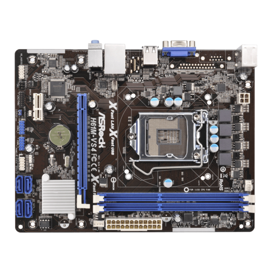
Page 14: Motherboard Layout
1.3 Motherboard Layout CPU_FAN1 ATX12V1 RoHS USB 2.0 T: USB0 B: USB1 HDMI1* USB 2.0 Top: T: USB2 RJ-45 Fast LAN Fast USB B: USB3 Fast RAM CHA_FAN1 PCIE1 Intel CMOS BATTERY AUDIO CODEC 32Mb BIOS PCIE2 SATA_3 SATA_1 PLED1 SPDIF_OUT1 USB4_5 USB6_7... -
Page 15: I/O Panel
LAN Port LED Indications ACT/LINK SPEED Activity/Link LED SPEED LED Status Description Status Description No Link H61M-PS4 / H61M-HG4 / H61M-VG4: Blinking Data Activity 10Mbps connection Link Orange 100Mbps connection LAN Port Green 1Gbps connection H61M-VS4: 10Mbps connection 100Mbps connection... - Page 16 To enable Multi-Streaming function, you need to connect a front panel audio cable to the front panel audio header. Please refer to below steps for the software setting of Multi-Streaming. ® For Windows After restarting your computer, you will ind “Mixer” tool on your system. Please select “Mixer ToolBox”...
-
Page 17: Installation
Chapter 2: Installation This is a Micro ATX form factor motherboard. Before you install the motherboard, study the coniguration of your chassis to ensure that the motherboard its into it. Make sure to unplug the power cord before installing or removing the motherboard. -
Page 18: Cpu Installation
2.3 CPU Installation For the installation of Intel 1155-Pin CPU, please follow the steps below. Load Plate Load Lever Socket Body Contact Array 1155-Pin Socket Overview Before you insert the 1155-Pin CPU into the socket, please check if the CPU surface is unclean or if there is any bent pin on the socket. Do not force to insert the CPU into the socket if above situation is found. - Page 19 Step 3. Insert the 1155-Pin CPU: Step 3-1. Hold the CPU by the edge where is marked with black line. Step 3-2. Orient the CPU with IHS (Integrated Heat Sink) up. Locate Pin1 and the two orientation key notches. orientation key notch alignment key Pin1 Pin1...
-
Page 20: Installation Of Cpu Fan And Heatsink
Installation of CPU Fan and Heatsink This motherboard is equipped with 1155-Pin socket that supports Intel 1155-Pin CPU. Please adopt the type of heatsink and cooling fan compliant with Intel 1155- Pin CPU to dissipate heat. Before you installed the heatsink, you need to spray thermal interface material between the CPU and the heatsink to improve heat dis- sipation. -
Page 21: Installation Of Memory Modules (Dimm)
2.5 Installation of Memory Modules (DIMM) This motherboard provides two 240-pin DDR3 (Double Data Rate 3) DIMM slots, and supports Dual Channel Memory Technology. For dual channel configuration, you always need to install two identical (the same brand, speed, size and chip- type) memory modules in the DDR3 DIMM slots to activate Dual Channel Memory Technology. -
Page 22: Expansion Slots (Pci Express Slots)
2.6 Expansion Slots (PCI Express Slots) There are 2 PCI Express slots on this motherboard. PCIE slots: PCIE1 (PCIE 3.0 x16 slot) is used for PCI Express x16 lane width graphics cards. PCIE2 (PCIE 2.0 x1 slot) is used for PCI Express x1 lane width cards. Only PCIE1 slot supports Gen 3 speed. -
Page 23: Jumpers Setup
2.7 Jumpers Setup The illustration shows how jumpers are setup. When the jumper cap is placed on pins, the jumper is “Short”. If no jumper cap is placed on pins, the jumper is “Open”. The illustration shows a 3-pin jumper whose pin1 and pin2 are “Short”... -
Page 24: Onboard Headers And Connectors
2.8 Onboard Headers and Connectors Onboard headers and connectors are NOT jumpers. Do NOT place jumper caps over these headers and connectors. Placing jumper caps over the headers and connectors will cause permanent damage of the motherboard! Serial ATA2 Connectors These four Serial ATA2 (SATA2) connectors support (SATA_0: see p.14, No. -
Page 25: Front Panel Audio Header
Front Panel Audio Header This is an interface for front PRESENCE# (9-pin HD_AUDIO1) panel audio cable that allows MIC_RET OUT_RET (see p.14 No. 18) convenient connection and control of audio devices. OUT2_L J_SENSE OUT2_R MIC2_R MIC2_L 1. High Deinition Audio supports Jack Sensing, but the panel wire on the chassis must support HDA to function correctly. - Page 26 is on when the system is operating. The LED keeps blinking when the sys- tem is in S1 sleep state. The LED is off when the system is in S3/S4 sleep state or powered off (S5). HDLED (Hard Drive Activity LED): Connect to the hard drive activity LED on the chassis front panel.
- Page 27 ATX Power Connector Please connect an ATX power (24-pin ATXPWR1) supply to this connector. (see p.14 No. 4) Though this motherboard provides 24-pin ATX power connector, it can still work if you adopt a traditional 20-pin ATX power supply. To use the 20-pin ATX power supply, please plug your power supply along with Pin 1 and Pin 13.
- Page 28 LPC/TPM Header This connector supports Trusted Platform Module (TPM) (13-pin LPC/TPM1) (see p.14, No. 16) system, which can securely store keys, digital certiicates, passwords, and data. A TPM system also helps enhance network security, protects digital identities, and ensures platform integrity. PIN Signal Name PIN Signal Name No pin...
-
Page 29: Driver Installation Guide
2.9 Driver Installation Guide To install the drivers to your system, please insert the support CD to your optical drive irst. Then, the drivers compatible to your system can be auto-detected and listed on the support CD driver page. Please follow the order from up to bottom side to install those required drivers. -
Page 30: Installing Windows
® STEP 3: Install Windows XP / XP 64-bit OS on your system. ® After making a SATA / SATA2 driver diskette, you can start to install Windows ® / XP 64-bit on your system. At the beginning of Windows setup, press F6 to install a third-party AHCI driver. -
Page 31: Asrock Xfast 555
2.11 ASRock XFast 555 ASRock’s unique XFast 555 Technology includes three tools that allow users to experience huge performance boosts. There is XFast RAM for 5 times better system speed, XFast LAN for 5 times faster LAN speed and XFast USB for 5 times faster... -
Page 32: Asrock Xfast Ram
2.11.1 ASRock XFast RAM ASRock XFast RAM is a new function that is included in ASRock Extreme Tuning Utility (AXTU). It fully utilizes the memory space that cannot be used under Win- ® dows 32-bit OS. ASRock XFast RAM shortens the loading time of previously visited websites, making web suring faster than ever. -
Page 33: Xfast Ram Settings
XFast RAM Settings You may ind the XFast RAM setup page in the left panel of ASRock Extreme Tun- ing utility. First select the desired drive and disk size to create a virtual drive. ® To access more than 4GB of RAM in Windows 32-bit OS, please leave PAE mode set to ON. - Page 34 Lastly, select the iles that are supposed to go in the virtual drive to speed up the system’s performance. Such as temporary iles created by computer programs when they cannot allocate enough memory for its tasks. Or internet cache iles including html, images, Cascading Style Sheets and JavaScript scripts from IE, Firefox and Google Chrome.
-
Page 35: Asrock Xfast Lan
2.11.2 ASRock XFast LAN ASRock XFast LAN provides several special features for faster internet access. For example, LAN Application Prioritization allows you to conigure your application’s pri- ority ideally or add new programs to the priority list. Trafic Shaping helps you watch Youtube HD videos and download iles simultaneously without hiccups. - Page 36 ASRock XFast LAN UI Overview The default status window Low Latency Mode switch arrow down = currently on (if needed) Open slot coniguration arrow up = always on Download activity display dialog no arrow = off Open Current TX shaping...
- Page 37 Close Windows Hides the status window. Can also be done by double clicking on the status window. Reopen by right clicking on the XFast LAN icon on the bottom right and selecting Open windows. Window settings Users may conigure the skin and effects of the user interface. Make the keyboard LEDs display Trafic Shaping information.
-
Page 38: Adding A New Application And Changing Its Priority
Adding a new application and changing its priority Click search and choose a new program you wish to add. You can also type in a short description for the program. Set the priority for the program and TX Limit then click Add to conirm. Hit the switch button to change conigurations or Delete to remove the application from the priority list. -
Page 39: Asrock Xfast Usb
2.11.3 ASRock XFast USB Not only does ASRock XFast USB boost up the performance of USB 2.0 storage devices, but also USB 3.0 devices. Users may experience up to ive times faster USB data transfer speed! - Page 40 ASRock XFast USB UI Overview Hide the XFast USB window Select your language Select a connected USB Click to activate/ storage device deactivate Turbo mode Click to safely remove Select Normal mode or the USB hard drive Turbo mode Plug in your USB storage device and XFast USB automatically sets it to Turbo...
-
Page 41: Uefi Setup Utility
Chapter 3: UEFI SETUP UTILITY Introduction This section explains how to use the UEFI SETUP UTILITY to conigure your system. The UEFI chip on the motherboard stores the UEFI SETUP UTILITY. You may run the UEFI SETUP UTILITY when you start up the computer. Please press <F2>... -
Page 42: Navigation Keys
3.1.2 Navigation Keys Please check the following table for the function description of each navigation key. Navigation Key(s) Function Description Moves cursor left or right to select Screens Moves cursor up or down to select items + / - To change option for the selected items <Tab>... - Page 43 H61M-HG4 H61M-VG4 H61M-VS4...
-
Page 44: Oc Tweaker Screen
3.3 OC Tweaker Screen In the OC Tweaker screen, you can set up overclocking features. CPU Coniguration CPU Ratio Use this item to change the ratio value of this motherboard. Intel SpeedStep Technology Intel SpeedStep technology is Intel’s new power saving technology. Pro- cessors can switch between multiple frequencies and voltage points to en- able power saving. - Page 45 Short Duration Power Limit Use this item to conigure short duration power limit in watts. The default value is [Auto]. Primary Plane Current Limit Use this item to conigure the maximum instantaneous current allowed for the primary plane. The default value is [Auto]. Secondary Plane Current Limit Use this item to conigure the maximum instantaneous current allowed for the secondary plane.
- Page 46 DRAM tRP Use this item to change Row Precharge Time (tRP) Auto/Manual setting. The default is [Auto]. DRAM tRAS Use this item to change RAS# Active Time (tRAS) Auto/Manual setting. The default is [Auto]. Command Rate (CR) Use this item to change Command Rate (CR) Auto/Manual setting. The default is [Auto].
- Page 47 MRC Fast Boot Use this item to enable or disable MRC Fast Boot. The default is [Enabled]. Voltage Coniguration DRAM Voltage Use this to select DRAM Voltage. The default value is [Auto].
-
Page 48: Advanced Screen
3.4 Advanced Screen In this section, you may set the conigurations for the following items: CPU Conigu- ration, North Bridge Coniguration, South Bridge Coniguration, Storage Conigura- tion, Intel(R) Rapid Start Technology, Intel(R) Smart Connect Technology, Super IO Coniguration, ACPI Coniguration and USB Coniguration. Setting wrong values in this section may cause the system to malfunction. -
Page 49: Cpu Coniguration
3.4.1 CPU Coniguration Intel Hyper Threading Technology To enable this feature, a computer system with an Intel processor that sup- ports Hyper-Threading technology and an operating system that includes ® ® optimization for this technology, such as Microsoft Windows XP / Vista ®... - Page 50 to the IA-32 Intel Architecture. An IA-32 processor with “No Execute (NX) Memory Protection” can prevent data pages from being used by malicious software to execute codes. This option will be hidden if the current CPU does not support No-Excute Memory Protection. Intel Virtualization Technology When this option is set to [Enabled], a VMM (Virtual Machine Architecture) can utilize the additional hardware capabilities provided by Vanderpool...
-
Page 51: North Bridge Coniguration
3.4.2 North Bridge Coniguration Primary Graphics Adapter This allows you to select [Onboard] or [PCI Express] as the boot graphic adapter priority. The default value is [PCI Express]. VT-d ® ® Use this to enable or disable Intel VT-d technology (Intel Virtualization Technology for Directed I/O). The default value of this feature is [Disabled]. PCIE1 Link Speed This allows you to select PCIE1 Link Speed. -
Page 52: South Bridge Coniguration
3.4.3 South Bridge Coniguration Onboard HD Audio Select [Auto], [Enabled] or [Disabled] for the onboard HD Audio feature. If you select [Auto], the onboard HD Audio will be disabled when PCI Sound Card is plugged. Front Panel Select [Auto] or [Disabled] for the onboard HD Audio Front Panel. Onboard LAN This allows you to enable or disable the Onboard LAN feature. -
Page 53: Storage Coniguration
3.4.4 Storage Coniguration SATA Controller(s) Use this item to enable or disable the SATA Controller feature. SATA Mode Selection Use this to select SATA mode. Coniguration options: [IDE Mode], [AHCI Mode] and [Disabled]. The default value is [AHCI Mode]. AHCI (Advanced Host Controller Interface) supports NCQ and other new features that will improve SATA disk performance but IDE mode does not have these advantages. -
Page 54: Intel(R) Rapid Start Technology
3.4.5 Intel(R) Rapid Start Technology Intel(R) Rapid Start Technology Use this item to enable or disable Intel(R) Rapid Start Technology. Intel(R) Rapid Start Technology is a new zero power hibernation mode which al- lows users to resume in just 5-6 seconds. The default is [Enabled]. Entry After Select a time to enable RTC wake timer at S3 entry. -
Page 55: Intel(R) Smart Connect Technology
3.4.6 Intel(R) Smart Connect Technology Intel(R) Smart Connect Technology Use this item to enable or disable Intel(R) Smart Connect Technology. Intel(R) Smart Connect Technology keeps your e-mail and social networks, such as Twitter, Facebook, etc. updated automatically while the computer is in sleep mode. -
Page 56: Super Io Coniguration
3.4.7 Super IO Coniguration Serial Port Use this item to enable or disable the onboard serial port. Port Address Use this item to set the address for the onboard serial port. Coniguration options: [3F8 / IRQ4] and [3E8 / IRQ4]. Infrared Port Use this item to enable or disable the onboard infrared port. * Serial Port is for H61M-PS4 only. -
Page 57: Acpi Coniguration
3.4.8 ACPI Coniguration Suspend to RAM Use this item to select whether to auto-detect or disable the Suspend-to- RAM feature. Selecting [Auto] will enable this feature if the OS supports it. Check Ready Bit Use this item to enable or disable the feature Check Ready Bit. ACPI HPET Table Use this item to enable or disable ACPI HPET Table. -
Page 58: Usb Coniguration
Please disable CSM when you enable Fast Boot option. The default value is [Enabled]. 3.4.9 USB Coniguration USB 2.0 Controller Use this item to enable or disable the use of USB 2.0 controller. Legacy USB Support Use this option to select legacy support for USB devices. There are four coniguration options: [Enabled], [Auto], [Disabled] and [UEFI Setup Only]. -
Page 59: Tool
3.5 Tool OMG(Online Management Guard) Administrators are able to establish an internet curfew or restrict internet access at speciied times via OMG. You may schedule the starting and ending hours of internet access granted to other users. In order to prevent users from bypassing OMG, guest accounts without permission to modify the system time are required. - Page 60 Network Coniguration Internet Setting Use this item to set up the internet connection mode. Coniguration options: [DHCP (Auto IP)] and [PPPOE]. UEFI Download Server Use this item to select UEFI irmware download server for Internet Flash. Coniguration options: [Asia], [Europe], [USA] and [China]. Dehumidiier Function Users may prevent motherboard damages due to dampness by enabling “Dehumidiier Function”.
-
Page 61: Hardware Health Event Monitoring Screen
3.6 Hardware Health Event Monitoring Screen In this section, it allows you to monitor the status of the hardware on your system, including the parameters of the CPU temperature, motherboard temperature, CPU fan speed, chassis fan speed, and the critical voltage. CPU Fan 1 Setting This allows you to set the CPU fan 1 speed. -
Page 62: Boot Screen
3.7 Boot Screen In this section, it will display the available devices on your system for you to conig- ure the boot settings and the boot priority. Fast Boot Fast Boot minimizes your computer’s boot time. There are three con- iguration options: [Disabled], [Fast] and [Ultra Fast]. - Page 63 Full Screen Logo Use this item to enable or disable OEM Logo. The default value is [En- abled]. AddOn ROM Display Use this option to adjust AddOn ROM Display. If you enable the option “Full Screen Logo” but you want to see the AddOn ROM information when the system boots, please select [Enabled].
-
Page 64: Security Screen
3.8 Security Screen In this section, you may set or change the supervisor/user password for the system. For the user password, you may also clear it. Secure Boot Use this to enable or disable Secure Boot. The default value is [Disabled]. -
Page 65: Exit Screen
3.9 Exit Screen Save Changes and Exit When you select this option, the following message “Save coniguration changes and exit setup?” will pop-out. Select [Yes] to save the changes and exit the UEFI SETUP UTILITY. Discard Changes and Exit When you select this option, the following message “Discard changes and exit setup?”... -
Page 66: Software Support
Click on a speciic item then follow the installation wizard to install it. 4.2.4 Contact Information If you need to contact ASRock or want to know more about ASRock, welcome to visit ASRock’s website at http://www.asrock.com; or you may contact your dealer for further information. -
Page 67: Installing Os On A Hdd Larger Than 2Tb
Installing OS on a HDD Larger Than 2TB ® This motherboard is adopting UEFI BIOS that allows Windows OS to be installed on a large size HDD (>2TB). Please follow below procedure to install the operating system. ® 1. Please make sure to use Windows Vista 64-bit (with SP1 or above), ®...
Need help?
Do you have a question about the H61M-VG4 and is the answer not in the manual?
Questions and answers