Table of Contents
Advertisement
Advertisement
Table of Contents

Related Manuals for ASROCK H81M-VG4 R2.0


Summary of Contents for ASROCK H81M-VG4 R2.0
- Page 1 H81M-VG4 R2.0 H81M-VG4 R2.0 H 8 1 M - V G 4 R 2 . 0 H 8 1 M - V G 4 R 2 . 0...
-
Page 2: Copyright Notice
(including damages for loss of proits, loss of business, loss of data, interruption of business and the like), even if ASRock has been advised of the possibility of such damages arising from any defect or error in the documentation or product. -
Page 3: Table Of Contents
Installing Memory Modules (DIMM) Expansion Slots (PCI Express Slots) Jumpers Setup Onboard Headers and Connectors Chapter 3 Software and Utilities Operation Installing Drivers A-Tuning Intel® Smart Connect Technology ASRock APP Shop 3.4.1 UI Overview 3.4.2 Apps 3.4.3 BIOS & Drivers 3.4.4 Setting Start8... - Page 4 Chapter 4 UEFI SETUP UTILITY Introduction 4.1.1 UEFI Menu Bar 4.1.2 Navigation Keys Main Screen OC Tweaker Screen Advanced Screen 4.4.1 CPU Coniguration 4.4.2 Chipset Coniguration 4.4.3 Storage Coniguration 4.4.4 Intel® Smart Connect Technology 4.4.5 Super IO Coniguration 4.4.6 ACPI Coniguration 4.4.7 USB Coniguration 4.4.8 Trusted Computing Tools...
-
Page 5: Chapter 1 Introduction
ASRock’s website without further notice. If you require technical support related to this motherboard, please visit our website for speciic information about the model you are using. You may ind the latest VGA cards and CPU support list on ASRock’s website as well. ASRock website http://www.asrock.com. -
Page 6: Speciications
• Pixel Shader 5.0, DirectX 11.1 • Max. shared memory 1792MB • Supports D-Sub with max. resolution up to 1920x1200 @ 60Hz • 5.1 CH HD Audio (Realtek ALC662 Audio Codec) Audio • Supports Surge Protection (ASRock Full Spike Protection) - Page 7 • Supports PXE • 1 x PS/2 Mouse/Keyboard Port Rear Panel • 1 x D-Sub Port • 4 x USB 2.0 Ports (Supports ESD Protection (ASRock Full Spike Protection)) • 2 x USB 3.0 Ports (Supports ESD Protection (ASRock Full Spike Protection)) • 1 x RJ-45 LAN Port with LED (ACT/LINK LED and SPEED...
- Page 8 Due to limitation, the actual memory size may be less than 4GB for the reservation for system usage under Windows® 32-bit operating systems. Windows® 64-bit operat- ing systems do not have such limitations. You can use ASRock XFast RAM to utilize the memory that Windows® cannot use.
-
Page 9: Motherboard Layout
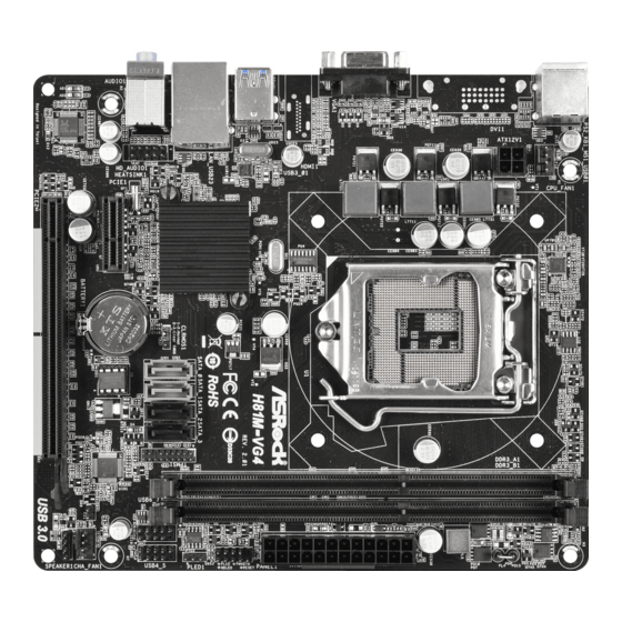
H81M-VG4 R2.0 1.3 Motherboard Layout CPU_FAN1 ATX12V1 USB 3.0 T: USB1 B: USB0 H81M-VG4 USB 2.0 Intel Top: T: USB3 RoHS RJ-45 PLED1 B: USB2 CLRCMOS1 USB6_7 USB4_5 HD_AUDIO1 TPMS1 CMOS Battery 32Mb PCIE1 BIOS CHA_FAN1 Audio SPEAKER1 CODEC PCIE2... - Page 10 No. Description CPU Fan Connector (CPU_FAN1) 2 x 240-pin DDR3 DIMM Slots (DDR3_A1, DDR3_B1) ATX Power Connector (ATXPWR1) System Panel Header (PANEL1) SATA2 Connector (SATA_2) SATA2 Connector (SATA_3) Power LED Header (PLED1) TPM Header (TPMS1) USB 2.0 Header (USB4_5) USB 2.0 Header (USB6_7) SATA3 Connector (SATA_1) SATA3 Connector (SATA_0) Chassis Fan Connector (CHA_FAN1)
-
Page 11: I/O Panel
H81M-VG4 R2.0 1.4 I/O Panel No. Description No. Description USB 2.0 Ports (USB01) USB 2.0 Ports (USB23) LAN RJ-45 Port* USB 3.0 Ports (USB3_01) Line In (Light Blue) D-Sub Port Front Speaker (Lime) PS/2 Mouse/Keyboard Port Microphone (Pink) * here are two LEDs on each LAN port. Please refer to the table below for the LAN port LED indications. -
Page 12: Chapter 2 Installation
Chapter 2 Installation his is a Micro ATX form factor motherboard. Before you install the motherboard, study the coniguration of your chassis to ensure that the motherboard its into it. Pre-installation Precautions Take note of the following precautions before you install motherboard components or change any motherboard settings. -
Page 13: Installing The Cpu
H81M-VG4 R2.0 2.1 Installing the CPU 1. Before you insert the 1150-Pin CPU into the socket, please check if the PnP cap is on the socket, if the CPU surface is unclean, or if there are any bent pins in the socket. - Page 14 English...
- Page 15 H81M-VG4 R2.0 Please save and replace the cover if the processor is removed. he cover must be placed if you wish to return the motherboard for ater service.
-
Page 16: Installing The Cpu Fan And Heatsink
2.2 Installing the CPU Fan and Heatsink... -
Page 17: Installing Memory Modules (Dimm)
H81M-VG4 R2.0 2.3 Installing Memory Modules (DIMM) his motherboard provides two 240-pin DDR3 (Double Data Rate 3) DIMM slots, and supports Dual Channel Memory Technology. 1. For dual channel coniguration, you always need to install identical (the same brand, speed, size and chip-type) DDR3 DIMM pairs. - Page 18 English...
-
Page 19: Expansion Slots (Pci Express Slots)
H81M-VG4 R2.0 2.4 Expansion Slots (PCI Express Slots) here are 2 PCI Express slots on the motherboard. Before installing an expansion card, please make sure that the power supply is switched of or the power cord is unplugged. Please read the documentation of the expansion card and make necessary hardware settings for the card before you start the installation. -
Page 20: Jumpers Setup
2.5 Jumpers Setup he illustration shows how jumpers are setup. When the jumper cap is placed on the pins, the jumper is “Short”. If no jumper cap is placed on the pins, the jumper is “Open”. he illustration shows a 3-pin jumper whose pin1 and pin2 are “Short” when a jumper cap is placed on these 2 pins. -
Page 21: Onboard Headers And Connectors
H81M-VG4 R2.0 2.6 Onboard Headers and Connectors Onboard headers and connectors are NOT jumpers. Do NOT place jumper caps over these headers and connectors. Placing jumper caps over the headers and connectors will cause permanent damage to the motherboard. System Panel Header... - Page 22 Serial ATA2 Connectors hese two SATA2 (SATA_2: connectors support SATA see p.5, No. 5) data cables for internal (SATA_3: storage devices with up to see p.5, No. 6) 3.0 Gb/s data transfer rate. Serial ATA3 Connectors hese two SATA3 (SATA_0: connectors support SATA see p.5, No.
- Page 23 H81M-VG4 R2.0 Chassis Speaker Header Please connect the chassis DUMMY SPEAKER (4-pin SPEAKER1) speaker to this header. DUMMY (see p.5, No. 14) Power LED Header Please connect the chassis PLED- (3-pin PLED1) power LED to this header PLED+ PLED+ (see p.5, No. 7) to indicate system power status.he LED is on when...
- Page 24 Chassis Intrusion Header his motherboard (2-pin CI1) supports CASE OPEN Signal (see p.5, No. 15) detection feature that detects if the chassis cove has been removed. his feature requires a chassis with chassis intrusion detection design. TPM Header his connector supports (17-pin TPMS1) Trusted Platform Module (see p.5, No.
-
Page 25: Chapter 3 Software And Utilities Operation
H81M-VG4 R2.0 Chapter 3 Software and Utilities Operation 3.1 Installing Drivers he Support CD that comes with the motherboard contains necessary drivers and useful utilities that enhance the motherboard’s features. Running The Support CD To begin using the support CD, insert the CD into your CD-ROM drive. he CD automatically displays the Main Menu if “AUTORUN”... -
Page 26: A-Tuning
3.2 A-Tuning A-Tuning is ASRock’s multi purpose sotware suite with a new interface, more new features and improved utilities, including XFast RAM, Dehumidiier, Good Night LED, FAN-Tastic Tuning, OC Tweaker and a whole lot more. 3.2.1 Installing A-Tuning When you install the all-in-one driver to your system from ASRock’s support CD, A-Tuning will be auto-installed as well. - Page 27 H81M-VG4 R2.0 Tools Various tools and utilities. XFast RAM Boost the system’s performance and extend the HDD’s or SDD’s lifespan! Create a hidden partition, then assign which iles should be stored in the RAM drive. XFast LAN Boost the speed of your internet connection! Select a speciic mode for making the designated program's priority highest.
- Page 28 FAN-Tastic Tuning Conigure up to ive diferent fan speeds using the graph. he fans will automatically shit to the next speed level when the assigned temperature is met. Dehumidiier Prevent motherboard damages due to dampness. Enable this function and conigure the period of time until the computer powers on, and the duration of the dehumidifying process.
- Page 29 H81M-VG4 R2.0 OC Tweaker Conigurations for overclocking the system. System Info View information about the system. *he System Browser tab may not appear for certain models.
- Page 30 Live Update Check for newer versions of BIOS or drivers. Tech Service Contact Tech Service if you have problems with your computer. Please leave your contact information along with details of the problem.
- Page 31 H81M-VG4 R2.0 Settings Conigure ASRock A-Tuning. Click to select "Auto run at Windows Startup" if you want A-Tuning to be launched when you start up the Windows operating system.
-
Page 32: Intel® Smart Connect Technology
3.3 Intel® Smart Connect Technology Intel® Smart Connect Technology is a feature that periodically wakes your computer from Windows® sleep state to refresh email or social networking applications. It saves your waiting time and keeps the content always up-to-date. 3.3.1 System Requirements •... -
Page 33: Setup Guide
3.3.2 Setup Guide Installing ASRock Smart Connect Utility Step 1 Install ASRock Smart Connect Utility, which is located in the folder at the following path of the Support CD: \ ASRock Utility > Smart Connect. Step 2 Once installed, run ASRock Smart Connect from your desktop or go to Windows... - Page 34 Step 3 Click the Add button. Take Foxmail as an example, add Foxmail to the Application list. Step 4 Select Foxmail from the Application List, then click the arrow pointing right to add this application to the Smart Connect List. Step 5 Click Apply to enable Smart Connect.
- Page 35 H81M-VG4 R2.0 Step 6 Double-click the Intel® Smart Connect Technology Manager icon in the Windows system tray. Step 7 Drag the slider to conigure how oten the system will connect to the network to download updates. Shorter durations will provide more frequent updates, but may cause more power consumption.
- Page 36 he system will wake up from sleep state periodically, and then start to update Foxmail. he screen will not display anything so the computer can maintain minimum power usage. Aterwards, the system will automatically return to sleep state again. Upon waking up the system, you will ind the new mail that were sent to you during sleep state are already updated and ready to be read in Foxmail.
-
Page 37: Asrock App Shop
Double-click on your desktop to access ASRock APP Shop utility. *You need to be connected to the Internet to download apps from the ASRock APP Shop. 3.4.1 UI Overview Category Panel Hot News... -
Page 38: Apps
3.4.2 Apps When the "Apps" tab is selected, you will see all the available apps on screen for you to download. Installing an App Step 1 Find the app you want to install. he most recommended app appears on the let side of the screen. he other various apps are shown on the right. - Page 39 H81M-VG4 R2.0 Step 3 If you want to install the app, click on the red icon to start downloading. Step 4 When installation completes, you can ind the green "Installed" icon appears on the upper right corner. To uninstall it, simply click on the trash can icon...
- Page 40 Upgrading an App You can only upgrade the apps you have already installed. When there is an available new version for your app, you will ind the mark of "New Version" appears below the installed app icon. Step 1 Click on the app icon to see more details. Step 2 Click on the yellow icon to start upgrading.
-
Page 41: Bios & Drivers
H81M-VG4 R2.0 3.4.3 BIOS & Drivers Installing BIOS or Drivers When the "BIOS & Drivers" tab is selected, you will see a list of recommended or critical updates for the BIOS or drivers. Please update them all soon. Step 1 Please check the item information before update. -
Page 42: Setting
3.4.4 Setting In the "Setting" page, you can change the language, select the server location, and determine if you want to automatically run the ASRock APP Shop on Windows startup. -
Page 43: Start8
3.5.1 Installing Start8 Install Start8, which is located in the folder at the following path of the Support CD: \ ASRock Utility > Start8. 3.5.2 Coniguring Start8 Style Select between the Windows 7 style and Windows 8 style Start Menu. hen select... - Page 44 Conigure Conigure provides coniguration options, including icon sizes, which shortcuts you want Start Menu to display, quick access to recently used apps, the functionality of the power button, and more. Control...
- Page 45 H81M-VG4 R2.0 Control lets you conigure what a click on the start button or a press on the Windows key does. Desktop Desktop allows you to disable the hot corners when you are working on the desktop. It also lets you choose whether or not the system boots directly into desktop mode and bypass the Metro user interface.
-
Page 46: Chapter 4 Uefi Setup Utility
Chapter 4 UEFI SETUP UTILITY 4.1 Introduction ASRock Interactive UEFI is a blend of system coniguration tools, cool sound efects and stunning visuals. Not only will it make BIOS setup less diicult but also a lot more amusing. his section explains how to use the UEFI SETUP UTILITY to conigure your system. -
Page 47: Navigation Keys
H81M-VG4 R2.0 4.1.2 Navigation Keys Use < > key or < > key to choose among the selections on the menu bar, and use < > key or < > key to move the cursor up or down to select items, then press <Enter>... -
Page 48: Main Screen
When you enter the UEFI SETUP UTILITY, the Main screen will appear and display the system overview. Active Page on Entry Select the default page when entering the UEFI setup utility. UEFI Guide UEFI Guide is a quick tutorial for ASRock's UEFI setup Utility. You may abort the tutorial by pressing "esc". -
Page 49: Oc Tweaker Screen
H81M-VG4 R2.0 4.3 OC Tweaker Screen In the OC Tweaker screen, you can set up overclocking features. Because the UEFI sotware is constantly being updated, the following UEFI setup screens and descriptions are for reference purpose only, and they may not exactly match what you see on your screen. -
Page 50: Long Duration Maintained
CPU Coniguration Multi core enhancement Improve the system's performance by forcing the CPU to perform the highest frequency on all CPU cores simultaneously. Disable to reduce power consumption. CPU Ratio he CPU speed is determined by the CPU Ratio multiplied with the BCLK. Increasing the CPU Ratio will increase the internal CPU clock speed without afecting the clock speed of other components. -
Page 51: Dram Timing Coniguration
H81M-VG4 R2.0 Primary Plane Current Limit Conigure the current limit of the CPU under Turbo Mode in ampere. A lower limit can protect the CPU and save power, while a higher limit may improve performance. GT Frequency Conigure the frequency of the integrated GPU. -
Page 52: Dram Coniguration
DRAM Coniguration CAS# Latency (tCL) he time between sending a column address to the memory and the beginning of the data in response. RAS# to CAS# Delay (tRCD) he number of clock cycles required between the opening of a row of memory and accessing columns within it. - Page 53 H81M-VG4 R2.0 Refresh Cycle Time (tRFC) he number of clocks from a Refresh command until the irst Activate command to the same rank. RAS to RAS Delay (tRRD) he number of clocks between two rows activated in diferent banks of the same rank.
- Page 54 tWRRDDR Conigure between module write to read delay from diferent ranks. tWRRDDD Use this to change DRAM tRRSR Auto/Manual settings. he default is [Auto]. Conigure between module write to read delay from diferent DIMMs. tWRWR Conigure between module write to write delay. tWRWRDR Conigure between module write to write delay from diferent ranks.
-
Page 55: Fivr Coniguration
H81M-VG4 R2.0 ODT WR (CHB) Conigure the memory on die termination resistors' WR for channel B. ODT NOM (CHA) Use this to change ODT (CHA) Auto/Manual settings. he default is [Auto]. ODT NOM (CHB) Use this to change ODT (CHB) Auto/Manual settings. he default is [Auto]. -
Page 56: Voltage Coniguration
System Agent Voltage Ofset Conigure the voltage for the System Agent. Setting the voltage higher may increase system stability when overclocking. CPU Analog IO Voltage Ofset CPU I/O Analog Voltage. CPU Digital IO Voltage Ofset CPU I/O Digital Voltage. CPU Integrated VR Faults Disable FIVR Faults to raise the threshold to trigger CPU over current protection and over voltage protection for better overclocking capabilities. -
Page 57: Advanced Screen
H81M-VG4 R2.0 4.4 Advanced Screen In this section, you may set the conigurations for the following items: CPU Con- iguration, Chipset Coniguration, Storage Coniguration, Intel® Smart Connect Technology, Super IO Coniguration, ACPI Coniguration, USB Coniguration and Trusted Computing. Setting wrong values in this section may cause the system to malfunction. -
Page 58: Cpu Coniguration
4.4.1 CPU Coniguration Active Processor Cores Select the number of cores to enable in each processor package. CPU C States Support Enable CPU C States Support for power saving. It is recommended to keep C3, C6 and C7 all enabled for better power saving. Enhanced Halt State (C1E) Enable Enhanced Halt State (C1E) for lower power consumption. -
Page 59: Intel Virtualization Technology
H81M-VG4 R2.0 No-Execute Memory Protection Processors with No-Execution Memory Protection Technology may prevent certain classes of malicious bufer overlow attacks. Intel Virtualization Technology Intel Virtualization Technology allows a platform to run multiple operating systems and applications in independent partitions, so that one computer system can function as multiple virtual systems. -
Page 60: Chipset Coniguration
4.4.2 Chipset Coniguration Primary Graphics Adapter Select a primary VGA. PCIE1 Link Speed Select the link speed for PCIE1. Share Memory Conigure the size of memory that is allocated to the integrated graphics processor when the system boots up. IGPU Multi-Monitor Select disable to disable the integrated graphics when an external graphics card is installed. -
Page 61: Front Panel
H81M-VG4 R2.0 Front Panel Enable/disable front panel HD audio. Onboard LAN Enable or disable the onboard network interface controller. Deep Sleep Conigure deep sleep mode for power saving when the computer is shut down. Restore on AC/Power Loss Select the power state ater a power failure. If [Power Of] is selected, the power will remain of when the power recovers. -
Page 62: Storage Coniguration
4.4.3 Storage Coniguration SATA Controller(s) Enable/disable the SATA controllers. SATA Mode Selection IDE: For better compatibility. AHCI: Supports new features that improve performance. AHCI (Advanced Host Controller Interface) supports NCQ and other new features that will improve SATA disk performance but IDE mode does not have these advan- tages. -
Page 63: Intel® Smart Connect Technology
H81M-VG4 R2.0 4.4.4 Intel® Smart Connect Technology ® Intel Smart Connect Technology ® Intel Smart Connect Technology automatically updates your email and social networks, such as Twitter, Facebook, etc. while the computer is in sleep mode. -
Page 64: Super Io Coniguration
4.4.5 Super IO Coniguration PS2 Y-Cable Enable the PS2 Y-Cable or set this option to Auto. -
Page 65: Acpi Coniguration
H81M-VG4 R2.0 4.4.6 ACPI Coniguration Suspend to RAM It is recommended to select auto for ACPI S3 power saving. Check Ready Bit Enable to enter the operating system ater S3 only when the hard disk is ready, this is recommended for better system stability. - Page 66 USB Keyboard/Remote Power On Allow the system to be waked up by an USB keyboard or remote controller. USB Mouse Power On Allow the system to be waked up by an USB mouse.
-
Page 67: Usb Coniguration
H81M-VG4 R2.0 4.4.7 USB Coniguration USB Controller Enable or disable all the USB 2.0 ports. Intel USB 3.0 Mode Enable or disable all the USB 3.0 ports. It is recommended to select [Smart Auto]. Legacy USB Support Enable or disable Legacy OS Support for USB 2.0 devices. If you encounter USB compatibility issues it is recommended to disable legacy USB support. -
Page 68: Trusted Computing
4.4.8 Trusted Computing Security Device Support Enable to activate Trusted Platform Module (TPM) security for your hard disk drives. -
Page 69: Tools
H81M-VG4 R2.0 4.5 Tools UEFI Tech Service Contact ASRock Tech Service if you are having trouble with your PC. Please setup network coniguration before using UEFI Tech Service. Easy Driver Installer For users that don’t have an optical disk drive to install the drivers from our support... - Page 70 Internet Setting Enable or disable sound efects in the setup utility. UEFI Download Server Select a server to download the UEFI irmware. Dehumidiier Function If Dehumidiier Function is enabled, the computer will power on automatically to dehumidify the system ater entering S4/S5 state. Dehumidiier Period Conigure the period of time until the computer powers on and enables Dehumidiier ater entering S4/S5 state.
- Page 71 H81M-VG4 R2.0 Save User Default Type a proile name and press enter to save your settings as user default. Load User Default Load previously saved user defaults.
-
Page 72: Hardware Health Event Monitoring Screen
4.6 Hardware Health Event Monitoring Screen his section allows you to monitor the status of the hardware on your system, including the parameters of the CPU temperature, motherboard temperature, fan speed and voltage. CPU Fan 1 Setting Select a fan mode for CPU Fans 1, or choose Customize to set 5 CPU temperatures and assign a respective fan speed for each temperature. -
Page 73: Boot Screen
H81M-VG4 R2.0 4.7 Boot Screen his section displays the available devices on your system for you to conigure the boot settings and the boot priority. Fast Boot Fast Boot minimizes your computer's boot time. In fast mode you may not boot from an USB storage device. - Page 74 Full Screen Logo Enable to display the boot logo or disable to show normal POST messages. AddOn ROM Display Enable AddOn ROM Display to see the AddOn ROM messages or conigure the AddOn ROM if you've enabled Full Screen Logo. Disable for faster boot speed. Boot Failure Guard If the computer fails to boot for a number of times the system automatically restores the default settings.
- Page 75 H81M-VG4 R2.0 Launch PXE OpROM Policy Select UEFI only to run those that support UEFI option ROM only. Select Legacy only to run those that support legacy option ROM only. Launch Storage OpROM Policy Select UEFI only to run those that support UEFI option ROM only. Select Legacy only to run those that support legacy option ROM only.
-
Page 76: Security Screen
4.8 Security Screen In this section you may set or change the supervisor/user password for the system. You may also clear the user password. Supervisor Password Set or change the password for the administrator account. Only the administrator has authority to change the settings in the UEFI Setup Utility. Leave it blank and press enter to remove the password. -
Page 77: Exit Screen
H81M-VG4 R2.0 4.9 Exit Screen Save Changes and Exit When you select this option the following message, “Save coniguration changes and exit setup?” will pop out. Select [OK] to save changes and exit the UEFI SETUP UTILITY. Discard Changes and Exit When you select this option the following message, “Discard changes and exit... -
Page 78: Contact Information
Contact Information If you need to contact ASRock or want to know more about ASRock, you’re welcome to visit ASRock’s website at http://www.asrock.com; or you may contact your dealer for further information. For technical questions, please submit a support request form at http://www.asrock.com/support/tsd.asp...
Need help?
Do you have a question about the H81M-VG4 R2.0 and is the answer not in the manual?
Questions and answers