ASROCK H81M-HG4 User Manual
User manual
Hide thumbs
Also See for H81M-HG4:
- Quick install manual (68 pages) ,
- Quick installation manual (68 pages) ,
- User manual (78 pages)
Table of Contents
Advertisement
Advertisement
Table of Contents

Related Manuals for ASROCK H81M-HG4


Summary of Contents for ASROCK H81M-HG4
- Page 1 User Manual...
-
Page 2: Copyright Notice
(including damages for loss of profits, loss of business, loss of data, interruption of business and the like), even if ASRock has been advised of the possibility of such damages arising from any defect or error in the documentation or product. -
Page 3: Table Of Contents
Contents Chapter 1 Introduction Package Contents Specifications Unique Features Motherboard Layout I/O Panel Chapter 2 Installation Installing the CPU Installing the CPU Fan and Heatsink Installing Memory Modules (DIMM) Expansion Slots (PCI Express Slots) Jumpers Setup Onboard Headers and Connectors Chapter 3 Software and Utilities Operation Installing Drivers A-Tuning... - Page 4 Main Screen OC Tweaker Screen Advanced Screen 4.4.1 CPU Configuration 4.4.2 Chipset Configuration 4.4.3 Storage Configuration 4.4.4 Intel® Smart Connect Technology 4.4.5 Super IO Configuration 4.4.6 ACPI Configuration 4.4.7 USB Configuration 4.4.8 Trusted Computing Tools Hardware Health Event Monitoring Screen Boot Screen Security Screen Exit Screen...
-
Page 5: Chapter 1 Introduction
ASRock’s website without further notice. If you require technical support related to this motherboard, please visit our website for specific information about the model you are using. You may find the latest VGA cards and CPU support list on ASRock’s website as well. ASRock website http://www.asrock.com. -
Page 6: Specifications
• Pixel Shader 5.0, DirectX 11.1 • Max. shared memory 1792MB • Dual VGA output: support HDMI and D-Sub Ports by independent display controllers (H81M-HG4) • Dual VGA output: support DVI-D and D-Sub Ports by independent display controllers (H81M-DG4) • Supports HDMI Technology with max. resolution up to 1920x1200 @ 60Hz (H81M-HG4) • Supports DVI-D with max. - Page 7 • Supports Auto Lip Sync, Deep Color (12bpc), xvYCC and HBR (High Bit Rate Audio) with HDMI Port (Compliant HDMI monitor is required) (H81M-HG4) • Supports HDCP with HDMI Port (H81M-HG4) • Supports HDCP function with DVI-D Ports (H81M-DG4) • Supports Full HD 1080p Blu-ray (BD) playback with HDMI Port (H81M-HG4) • Supports Full HD 1080p Blu-ray (BD) playback with DVI-D...
- Page 8 • Microsoft® Windows® 8.1 32-bit / 8.1 64-bit / 8 32-bit / 8 64- bit / 7 32-bit / 7 64-bit Certifica- • FCC, CE, WHQL tions • ErP/EuP Ready (ErP/EuP ready power supply is required) * For detailed product information, please visit our website: http://www.asrock.com...
- Page 9 Due to limitation, the actual memory size may be less than 4GB for the reservation for system usage under Windows® 32-bit operating systems. Windows® 64-bit operat- ing systems do not have such limitations. You can use ASRock XFast RAM to utilize the memory that Windows® cannot use.
-
Page 10: Unique Features
LED, FAN-Tastic Tuning, OC Tweaker and a whole lot more. ASRock Instant Flash ASRock Instant Flash is a BIOS flash utility embedded in Flash ROM. This conve- nient BIOS update tool allows you to update the system BIOS in a few clicks without preparing an additional floppy diskette or other complicated flash utility. - Page 11 And it also boosts the speed of Adobe Photoshop 5 times faster. Another advantage of ASRock XFast RAM is that it reduces the frequency of accessing your SSDs or HDDs in order to extend their lifespan.
- Page 12 Windows® 8 brings the ultimate boot up experience. The lightning boot up speed makes it hard to access the UEFI setup. ASRock Restart to UEFI allows users to enter the UEFI automatically when turning on the PC. By enabling this function, the PC will enter the UEFI directly after you restart.
-
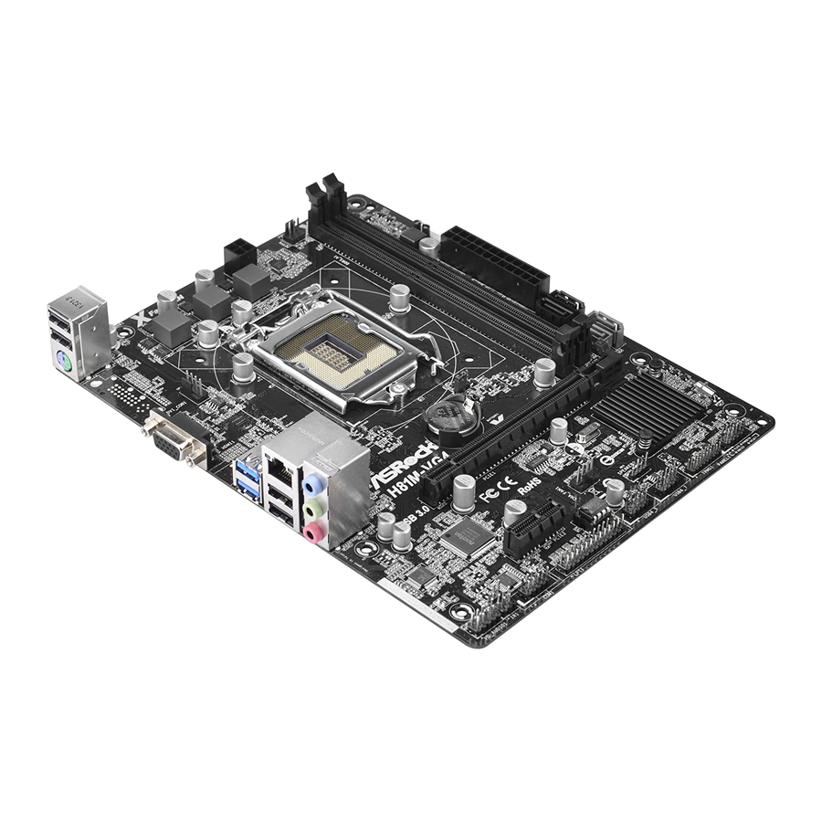
Page 13: Motherboard Layout
H81M-HG4/H81M-DG4/H81M-VG4 1.4 Motherboard Layout H81M-HG4: Fast RAM Fast LAN PWR_FAN1 ATX12V1 CPU_FAN1 HDMI1 USB 3.0 T: USB0 B: USB1 USB 2.0 CLRCMOS1 Top: T: USB2 RJ-45 B: USB3 CMOS Battery H81M-HG4 Fast USB PCIE1 USB 3.0 Intel RoHS Audio CODEC... - Page 14 H81M-DG4: Fast RAM Fast LAN PWR_FAN1 ATX12V1 CPU_FAN1 USB 3.0 T: USB0 B: USB1 USB 2.0 CLRCMOS1 Top: T: USB2 RJ-45 B: USB3 CMOS Battery H81M-DG4 Fast USB USB 3.0 PCIE1 Intel RoHS Audio CODEC CHA_FAN1 PCIE2 SPEAKER1 32Mb BIOS USB4_5 USB6_7 PLED PWRBTN...
- Page 15 H81M-HG4/H81M-DG4/H81M-VG4 H81M-VG4: Fast RAM Fast LAN PWR_FAN1 ATX12V1 CPU_FAN1 USB 3.0 T: USB0 B: USB1 USB 2.0 CLRCMOS1 Top: T: USB2 RJ-45 B: USB3 CMOS Battery H81M-VG4 Fast USB USB 3.0 PCIE1 Intel RoHS Audio CODEC CHA_FAN1 PCIE2 SPEAKER1 32Mb...
- Page 16 No. Description ATX 12V Power Connector (ATX12V1) Power Fan Connector (PWR_FAN1) 2 x 240-pin DDR3 DIMM Slots (DDR3_A1, DDR3_B1) ATX Power Connector (ATXPWR1) SATA2 Connector (SATA_3) SATA2 Connector (SATA_2) SATA3 Connector (SATA_0) SATA3 Connector (SATA_1) Clear CMOS Jumper (CLRCMOS1) System Panel Header (PANEL1) TPM Header (TPMS1) Chassis Speaker Header (SPEAKER1) USB 2.0 Header (USB6_7)
-
Page 17: I/O Panel
H81M-HG4/H81M-DG4/H81M-VG4 1.5 I/O Panel H81M-HG4: No. Description No. Description USB 2.0 Ports (USB01) USB 2.0 Ports (USB23) LAN RJ-45 Port* USB 3.0 Ports (USB3_01) Line In (Light Blue) HDMI Port Front Speaker (Lime) D-Sub Port Microphone (Pink) PS/2 Mouse/Keyboard Port * There are two LEDs on each LAN port. - Page 18 H81M-DG4: No. Description No. Description USB 2.0 Ports (USB01) USB 2.0 Ports (USB23) LAN RJ-45 Port* USB 3.0 Ports (USB3_01) Line In (Light Blue) D-Sub Port Front Speaker (Lime) DVI-D Port Microphone (Pink) PS/2 Mouse/Keyboard Port * There are two LEDs on each LAN port. Please refer to the table below for the LAN port LED indications. ACT/LINK LED SPEED LED LAN Port...
- Page 19 H81M-HG4/H81M-DG4/H81M-VG4 H81M-VG4: No. Description No. Description USB 2.0 Ports (USB01) USB 2.0 Ports (USB23) LAN RJ-45 Port* USB 3.0 Ports (USB3_01) Line In (Light Blue) D-Sub Port Front Speaker (Lime) PS/2 Mouse/Keyboard Port Microphone (Pink) * There are two LEDs on each LAN port. Please refer to the table below for the LAN port LED indications.
-
Page 20: Chapter 2 Installation
Chapter 2 Installation This is a Micro ATX form factor motherboard. Before you install the motherboard, study the configuration of your chassis to ensure that the motherboard fits into it. Pre-installation Precautions Take note of the following precautions before you install motherboard components or change any motherboard settings. -
Page 21: Installing The Cpu
H81M-HG4/H81M-DG4/H81M-VG4 2.1 Installing the CPU 1. Before you insert the 1150-Pin CPU into the socket, please check if the PnP cap is on the socket, if the CPU surface is unclean, or if there are any bent pins in the socket. - Page 23 H81M-HG4/H81M-DG4/H81M-VG4 Please save and replace the cover if the processor is removed. The cover must be placed if you wish to return the motherboard for after service.
-
Page 24: Installing The Cpu Fan And Heatsink
2.2 Installing the CPU Fan and Heatsink... -
Page 25: Installing Memory Modules (Dimm)
H81M-HG4/H81M-DG4/H81M-VG4 2.3 Installing Memory Modules (DIMM) This motherboard provides two 240-pin DDR3 (Double Data Rate 3) DIMM slots, and supports Dual Channel Memory Technology. 1. For dual channel configuration, you always need to install identical (the same brand, speed, size and chip-type) DDR3 DIMM pairs. -
Page 27: Expansion Slots (Pci Express Slots)
H81M-HG4/H81M-DG4/H81M-VG4 2.4 Expansion Slots (PCI Express Slots) There are 2 PCI Express slots on the motherboard. Before installing an expansion card, please make sure that the power supply is switched off or the power cord is unplugged. Please read the documentation of the expansion card and make necessary hardware settings for the card before you start the installation. -
Page 28: Jumpers Setup
2.5 Jumpers Setup The illustration shows how jumpers are setup. When the jumper cap is placed on the pins, the jumper is “Short”. If no jumper cap is placed on the pins, the jumper is “Open”. The illustration shows a 3-pin jumper whose pin1 and pin2 are “Short” when a jumper cap is placed on these 2 pins. -
Page 29: Onboard Headers And Connectors
H81M-HG4/H81M-DG4/H81M-VG4 2.6 Onboard Headers and Connectors Onboard headers and connectors are NOT jumpers. Do NOT place jumper caps over these headers and connectors. Placing jumper caps over the headers and connectors will cause permanent damage to the motherboard. System Panel Header... - Page 30 Serial ATA2 Connectors These two SATA2 (SATA_2: connectors support SATA see p.9, 10, 11, No. 6) data cables for internal (SATA_3: storage devices with up to see p.9, 10, 11, No. 5) 3.0 Gb/s data transfer rate. Serial ATA3 Connectors These two SATA3 (SATA_0: connectors support SATA...
- Page 31 H81M-HG4/H81M-DG4/H81M-VG4 1. High Definition Audio supports Jack Sensing, but the panel wire on the chassis must support HDA to function correctly. Please follow the instructions in our manual and chassis manual to install your system. 2. If you use an AC’97 audio panel, please install it to the front panel audio header by the steps below: A.
- Page 32 ATX 12V Power This motherboard Connector provides an 4-pin ATX (4-pin ATX12V1) 12V power connector. (see p.9, 10, 11, No. 1) Infrared Module Header This header supports an optional IRTX +5VSB (5-pin IR1) DUMMY wireless transmitting and (see p.9, 10, 11, No. 18) receiving infrared module.
- Page 33 H81M-HG4/H81M-DG4/H81M-VG4 Print Port Header This is an interface AFD# ERROR# PINIT# (25-pin LPT1) for print port cable SLIN# (see p.9, 10, 11, No. 16) that allows convenient SPD7 connection of printer SPD6 ACK# SPD5 BUSY SPD4 devices. SPD3 SLCT SPD2...
-
Page 34: Chapter 3 Software And Utilities Operation
Chapter 3 Software and Utilities Operation 3.1 Installing Drivers The Support CD that comes with the motherboard contains necessary drivers and useful utilities that enhance the motherboard’s features. Running The Support CD To begin using the support CD, insert the CD into your CD-ROM drive. The CD automatically displays the Main Menu if “AUTORUN”... -
Page 35: A-Tuning
H81M-HG4/H81M-DG4/H81M-VG4 3.2 A-Tuning A-Tuning is ASRock’s multi purpose software suite with a new interface, more new features and improved utilities, including XFast RAM, Dehumidifier, Good Night LED, FAN-Tastic Tuning, OC Tweaker and a whole lot more. 3.2.1 Installing A-Tuning When you install the all-in-one driver to your system from ASRock’s support CD, A-Tuning will be auto-installed as well. - Page 36 Tools Various tools and utilities. XFast RAM Boost the system’s performance and extend the HDD’s or SDD’s lifespan! Create a hidden partition, then assign which files should be stored in the RAM drive. Good Night LED Switch off the Power/HDD/LAN LEDs when the system is on, and automatically switch off the Power and Keyboard LEDs when the system enters into Standby/ Hibernation mode.
- Page 37 H81M-HG4/H81M-DG4/H81M-VG4 OC Tweaker Configurations for overclocking the system. System Info View information about the system. Tech Service Contact Tech Service.
-
Page 38: Intel® Smart Connect Technology
3.3 Intel® Smart Connect Technology Intel® Smart Connect Technology is a feature that periodically wakes your computer from Windows® sleep state to refresh email or social networking applications. It saves your waiting time and keeps the content always up-to-date. 3.3.1 System Requirements •... -
Page 39: Setup Guide
3.3.2 Setup Guide Installing ASRock Smart Connect Utility Step 1 Install ASRock Smart Connect Utility, which is located in the folder at the following path of the Support CD: \ ASRock Utility > Smart Connect. Step 2 Once installed, run ASRock Smart Connect from your desktop or go to Windows... - Page 40 Step 3 Click the Add button. Take Foxmail as an example, add Foxmail to the Application list. Step 4 Select Foxmail from the Application List, then click the arrow pointing right to add this application to the Smart Connect List. Step 5 Click Apply to enable Smart Connect.
- Page 41 H81M-HG4/H81M-DG4/H81M-VG4 Step 6 Double-click the Intel® Smart Connect Technology Manager icon in the Windows system tray. Step 7 Drag the slider to configure how often the system will connect to the network to download updates. Shorter durations will provide more frequent updates, but may cause more power consumption.
-
Page 42: Start8
3.4.1 Installing Start8 Install Start8, which is located in the folder at the following path of the Support CD: \ ASRock Utility > Start8. 3.4.2 Configuring Start8 Style Select between the Windows 7 style and Windows 8 style Start Menu. Then select... - Page 43 H81M-HG4/H81M-DG4/H81M-VG4 Configure Configure provides configuration options, including icon sizes, which shortcuts you want Start Menu to display, quick access to recently used apps, the functionality of the power button, and more. Control...
- Page 44 Control lets you configure what a click on the start button or a press on the Windows key does. Desktop Desktop allows you to disable the hot corners when you are working on the desktop. It also lets you choose whether or not the system boots directly into desktop mode and bypass the Metro user interface.
-
Page 45: Chapter 4 Uefi Setup Utility
Chapter 4 UEFI SETUP UTILITY 4.1 Introduction ASRock Interactive UEFI is a blend of system configuration tools, cool sound effects and stunning visuals. Not only will it make BIOS setup less difficult but also a lot more amusing. This section explains how to use the UEFI SETUP UTILITY to configure your system. -
Page 46: Navigation Keys
4.1.2 Navigation Keys Use < > key or < > key to choose among the selections on the menu bar, and use < > key or < > key to move the cursor up or down to select items, then press <Enter>... -
Page 47: Main Screen
H81M-HG4 Active Page on Entry Select the default page when entering the UEFI setup utility. UEFI Guide UEFI Guide is a quick tutorial for ASRock's UEFI setup Utility. You may abort the tutorial by pressing "esc". - Page 48 H81M-DG4 H81M-VG4...
-
Page 49: Oc Tweaker Screen
H81M-HG4/H81M-DG4/H81M-VG4 4.3 OC Tweaker Screen In the OC Tweaker screen, you can set up overclocking features. Because the UEFI software is constantly being updated, the following UEFI setup screens and descriptions are for reference purpose only, and they may not exactly match what you see on your screen. -
Page 50: Cpu Configuration
CPU Configuration Multi core enhancement Improve the system's performance by forcing the CPU to perform the highest frequency on all CPU cores simultaneously. Disable to reduce power consumption. CPU Ratio The CPU speed is determined by the CPU Ratio multiplied with the BCLK. Increasing the CPU Ratio will increase the internal CPU clock speed without affecting the clock speed of other components. -
Page 51: Long Duration Maintained
H81M-HG4/H81M-DG4/H81M-VG4 Long Duration Maintained Configure the period of time until the CPU ratio is lowered when the Long Duration Power Limit is exceeded. Short Duration Power Limit Configure Package Power Limit 2 in watts. When the limit is exceeded, the CPU ratio will be lowered immediately. -
Page 52: Dram Configuration
DRAM Configuration CAS# Latency (tCL) The time between sending a column address to the memory and the beginning of the data in response. RAS# to CAS# Delay (tRCD) The number of clock cycles required between the opening of a row of memory and accessing columns within it. - Page 53 H81M-HG4/H81M-DG4/H81M-VG4 Refresh Cycle Time (tRFC) The number of clocks from a Refresh command until the first Activate command to the same rank. RAS to RAS Delay (tRRD) The number of clocks between two rows activated in different banks of the same rank.
- Page 54 tWRRDDR Configure between module write to read delay from different ranks. tWRRDDD Use this to change DRAM tRRSR Auto/Manual settings. The default is [Auto]. Configure between module write to read delay from different DIMMs. tWRWR Configure between module write to write delay. tWRWRDR Configure between module write to write delay from different ranks.
- Page 55 H81M-HG4/H81M-DG4/H81M-VG4 ODT WR (CHB) Configure the memory on die termination resistors' WR for channel B. ODT NOM (CHA) Use this to change ODT (CHA) Auto/Manual settings. The default is [Auto]. ODT NOM (CHB) Use this to change ODT (CHB) Auto/Manual settings. The default is [Auto].
-
Page 56: Voltage Configuration
CPU Cache Override Voltage Add voltage to the CPU Cache when the system is under heavy load. CPU Cache Voltage Offset Configure the voltage for the CPU Cache. Setting the voltage higher may increase system stability when overclocking. System Agent Voltage Offset Configure the voltage for the System Agent. -
Page 57: Advanced Screen
H81M-HG4/H81M-DG4/H81M-VG4 4.4 Advanced Screen In this section, you may set the configurations for the following items: CPU Con- figuration, Chipset Configuration, Storage Configuration, Intel® Smart Connect Technology, Super IO Configuration, ACPI Configuration, USB Configuration and Trusted Computing. Setting wrong values in this section may cause the system to malfunction. -
Page 58: Cpu Configuration
4.4.1 CPU Configuration Active Processor Cores Select the number of cores to enable in each processor package. CPU C States Support Enable CPU C States Support for power saving. It is recommended to keep C3, C6 and C7 all enabled for better power saving. Enhanced Halt State (C1E) Enable Enhanced Halt State (C1E) for lower power consumption. -
Page 59: Intel Virtualization Technology
H81M-HG4/H81M-DG4/H81M-VG4 CPU Thermal Throttling Enable CPU internal thermal control mechanisms to keep the CPU from overheat- ing. No-Execute Memory Protection Processors with No-Execution Memory Protection Technology may prevent certain classes of malicious buffer overflow attacks. Intel Virtualization Technology Intel Virtualization Technology allows a platform to run multiple operating systems and applications in independent partitions, so that one computer system can function as multiple virtual systems. -
Page 60: Chipset Configuration
4.4.2 Chipset Configuration Primary Graphics Adapter Select a primary VGA. VT-d Intel® Virtualization Technology for Directed I/O helps your virtual machine monitor better utilize hardware by improving application compatibility and reliability, and providing additional levels of manageability, security, isolation, and I/O performance. -
Page 61: Render Standby
Front Panel Enable/disable front panel HD audio. Onboard HDMI HD Audio (Only for H81M-HG4/H81M-DG4) Enable audio for the onboard digital outputs. Onboard LAN Enable or disable the onboard network interface controller. -
Page 62: Storage Configuration
4.4.3 Storage Configuration SATA Controller(s) Enable/disable the SATA controllers. SATA Mode Selection IDE: For better compatibility. AHCI: Supports new features that improve performance. AHCI (Advanced Host Controller Interface) supports NCQ and other new features that will improve SATA disk performance but IDE mode does not have these advan- tages. -
Page 63: Intel® Smart Connect Technology
H81M-HG4/H81M-DG4/H81M-VG4 4.4.4 Intel® Smart Connect Technology ® Intel Smart Connect Technology ® Intel Smart Connect Technology automatically updates your email and social networks, such as Twitter, Facebook, etc. while the computer is in sleep mode. -
Page 64: Super Io Configuration
4.4.5 Super IO Configuration Serial Port Enable or disable the Serial port. Serial Port Address Select the address of the Serial port. Infrared Port Enable or disable the Infrared port. Parallel Port Enable or disable the Parallel port. Change Settings Select the address of the Parallel port. -
Page 65: Acpi Configuration
H81M-HG4/H81M-DG4/H81M-VG4 4.4.6 ACPI Configuration Suspend to RAM It is recommended to select auto for ACPI S3 power saving. Check Ready Bit Enable to enter the operating system after S3 only when the hard disk is ready, this is recommended for better system stability. - Page 66 RTC Alarm Power On Allow the system to be waked up by the real time clock alarm. Set it to By OS to let it be handled by your operating system. USB Keyboard/Remote Power On Allow the system to be waked up by an USB keyboard or remote controller. USB Mouse Power On Allow the system to be waked up by an USB mouse.
-
Page 67: Usb Configuration
H81M-HG4/H81M-DG4/H81M-VG4 4.4.7 USB Configuration USB Controller Enable or disable all the USB 2.0 ports. Intel USB 3.0 Mode Enable or disable all the USB 3.0 ports. It is recommended to select [Smart Auto]. Legacy USB Support Enable or disable Legacy OS Support for USB 2.0 devices. If you encounter USB compatibility issues it is recommended to disable legacy USB support. -
Page 68: Trusted Computing
4.4.8 Trusted Computing Security Device Support Enable to activate Trusted Platform Module (TPM) security for your hard disk drives. -
Page 69: Tools
H81M-HG4/H81M-DG4/H81M-VG4 4.5 Tools UEFI Tech Service Contact ASRock Tech Service if you are having trouble with your PC. Please setup network configuration before using UEFI Tech Service. Easy Driver Installer For users that don’t have an optical disk drive to install the drivers from our support... - Page 70 Internet Setting Enable or disable sound effects in the setup utility. UEFI Download Server Select a server to download the UEFI firmware. Dehumidifier Function If Dehumidifier Function is enabled, the computer will power on automatically to dehumidify the system after entering S4/S5 state. Dehumidifier Period Configure the period of time until the computer powers on and enables Dehumidifier after entering S4/S5 state.
- Page 71 H81M-HG4/H81M-DG4/H81M-VG4 Save User Default Type a profile name and press enter to save your settings as user default. Load User Default Load previously saved user defaults.
-
Page 72: Hardware Health Event Monitoring Screen
4.6 Hardware Health Event Monitoring Screen This section allows you to monitor the status of the hardware on your system, including the parameters of the CPU temperature, motherboard temperature, fan speed and voltage. CPU Fan 1 Setting Select a fan mode for CPU Fans 1, or choose Customize to set 5 CPU temperatures and assign a respective fan speed for each temperature. -
Page 73: Boot Screen
H81M-HG4/H81M-DG4/H81M-VG4 4.7 Boot Screen This section displays the available devices on your system for you to configure the boot settings and the boot priority. Fast Boot Fast Boot minimizes your computer's boot time. In fast mode you may not boot from an USB storage device. - Page 74 Full Screen Logo Enable to display the boot logo or disable to show normal POST messages. AddOn ROM Display Enable AddOn ROM Display to see the AddOn ROM messages or configure the AddOn ROM if you've enabled Full Screen Logo. Disable for faster boot speed. Boot Failure Guard If the computer fails to boot for a number of times the system automatically restores the default settings.
- Page 75 H81M-HG4/H81M-DG4/H81M-VG4 Launch PXE OpROM Policy Select UEFI only to run those that support UEFI option ROM only. Select Legacy only to run those that support legacy option ROM only. Launch Storage OpROM Policy Select UEFI only to run those that support UEFI option ROM only. Select Legacy only to run those that support legacy option ROM only.
-
Page 76: Security Screen
4.8 Security Screen In this section you may set or change the supervisor/user password for the system. You may also clear the user password. Supervisor Password Set or change the password for the administrator account. Only the administrator has authority to change the settings in the UEFI Setup Utility. Leave it blank and press enter to remove the password. -
Page 77: Exit Screen
H81M-HG4/H81M-DG4/H81M-VG4 4.9 Exit Screen Save Changes and Exit When you select this option the following message, “Save configuration changes and exit setup?” will pop out. Select [OK] to save changes and exit the UEFI SETUP UTILITY. Discard Changes and Exit When you select this option the following message, “Discard changes and exit... -
Page 78: Contact Information
Contact Information If you need to contact ASRock or want to know more about ASRock, you’re welcome to visit ASRock’s website at http://www.asrock.com; or you may contact your dealer for further information. For technical questions, please submit a support request form at http://www.asrock.com/support/tsd.asp...
Need help?
Do you have a question about the H81M-HG4 and is the answer not in the manual?
Questions and answers