Advertisement
Quick Links
Version 1.0
Published August 2014
Copyright©2014 ASRock INC. All rights reserved.
Copyright Notice:
No part of this documentation may be reproduced, transcribed, transmitted, or
translated in any language, in any form or by any means, except duplication of
documentation by the purchaser for backup purpose, without written consent of
ASRock Inc.
Products and corporate names appearing in this documentation may or may not
be registered trademarks or copyrights of their respective companies, and are used
only for identification or explanation and to the owners' benefit, without intent to
infringe.
Disclaimer:
Specifications and information contained in this documentation are furnished for
informational use only and subject to change without notice, and should not be
constructed as a commitment by ASRock. ASRock assumes no responsibility for
any errors or omissions that may appear in this documentation.
With respect to the contents of this documentation, ASRock does not provide
warranty of any kind, either expressed or implied, including but not limited to
the implied warranties or conditions of merchantability or fitness for a particular
purpose.
In no event shall ASRock, its directors, officers, employees, or agents be liable for
any indirect, special, incidental, or consequential damages (including damages for
loss of profits, loss of business, loss of data, interruption of business and the like),
even if ASRock has been advised of the possibility of such damages arising from any
defect or error in the documentation or product.
This device complies with Part 15 of the FCC Rules. Operation is subject to the following
two conditions:
(1) this device may not cause harmful interference, and
(2) this device must accept any interference received, including interference that
may cause undesired operation.
CALIFORNIA, USA ONLY
The Lithium battery adopted on this motherboard contains Perchlorate, a toxic substance
controlled in Perchlorate Best Management Practices (BMP) regulations passed by the
California Legislature. When you discard the Lithium battery in California, USA, please
follow the related regulations in advance.
"Perchlorate Material-special handling may apply, see www.dtsc.ca.gov/hazardouswaste/
perchlorate"
ASRock Website: http://www.asrock.com
Advertisement

Related Manuals for ASROCK H81M-DG6


Summary of Contents for ASROCK H81M-DG6
- Page 1 (including damages for loss of profits, loss of business, loss of data, interruption of business and the like), even if ASRock has been advised of the possibility of such damages arising from any defect or error in the documentation or product.
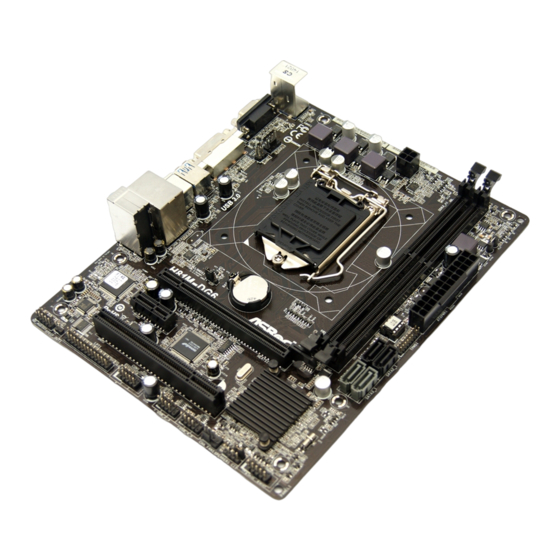
- Page 3 H81M-DG6 Motherboard Layout ATX12V1 CPU_FAN1 USB 3.0 T: USB0 B: USB1 32Mb USB 2.0 BIOS T: USB0 B: USB1 USB 2.0 Top: T: USB2 RJ-45 CMOS B: USB3 Battery CLRCMOS1 H81M-DG6 PCIE1 Intel PCIE2 RoHS Audio CODEC PCI1 PANEL1 CHA_FAN1...
-
Page 4: Table Of Contents
No. Description ATX 12V Power Connector (ATX12V1) 2 x 240-pin DDR3 DIMM Slots (DDR3_A1, DDR3_B1) ATX Power Connector (ATXPWR1) TPM Header (TPMS1) SATA2 Connector (SATA2_0) SATA2 Connector (SATA2_1) SATA3 Connector (SATA3_1) SATA3 Connector (SATA3_0) System Panel Header (PANEL1) Chassis Intrusion Header (CI1) Chassis Speaker Header (SPEAKER1) Chassis Fan Connector (CHA_FAN1) USB 2.0 Header (USB_4_5) - Page 5 H81M-DG6 I/O Panel No. Description No. Description PS/2 Mouse Port USB 2.0 Ports (USB_01) LAN RJ-45 Port* USB 3.0 Ports (USB3_01) Line In (Light Blue) DVI-D Port Front Speaker (Lime) D-Sub Port Microphone (Pink) PS/2 Keyboard Port USB 2.0 Ports (USB_23) * There are two LEDs on each LAN port.
- Page 6 ASRock’s website without further notice. If you require technical support related to this motherboard, please visit our website for specific information about the model you are using. You may find the latest VGA cards and CPU support list on ASRock’s website as well. ASRock website http://www.asrock.com.
- Page 7 H81M-DG6 1.2 Specifications Platform • Micro ATX Form Factor • Solid Capacitor for CPU power • High Density Glass Fabric PCB • Supports New 4 and 4 Generation Intel® Core i7/i5/i3/ Xeon®/Pentium®/Celeron® Processors (Socket 1150) • Digi Power design • Supports Intel® Turbo Boost 2.0 Technology Chipset • Intel®...
- Page 8 • 1 x PS/2 Keyboard Port • 1 x D-Sub Port • 1 x DVI-D Port • 4 x USB 2.0 Ports (Supports ESD Protection (ASRock Full Spike Protection)) • 2 x USB 3.0 Ports (Supports ESD Protection (ASRock Full Spike Protection)) • 1 x RJ-45 LAN Port with LED (ACT/LINK LED and SPEED...
-
Page 9: Tpm Header (Tpms1)
• Microsoft® Windows® 8.1 32-bit / 8.1 64-bit / 8 32-bit / 8 64- bit / 7 32-bit / 7 64-bit Certifica- • FCC, CE, WHQL tions • ErP/EuP ready (ErP/EuP ready power supply is required) * For detailed product information, please visit our website: http://www.asrock.com... - Page 10 Due to limitation, the actual memory size may be less than 4GB for the reservation for system usage under Windows® 32-bit operating systems. Windows® 64-bit operat- ing systems do not have such limitations. You can use ASRock XFast RAM to utilize the memory that Windows® cannot use.
- Page 11 H81M-DG6 1.3 Jumpers Setup The illustration shows how jumpers are setup. When the jumper cap is placed on the pins, the jumper is “Short”. If no jumper cap is placed on the pins, the jumper is “Open”. The illustration shows a 3-pin jumper whose pin1 and pin2 are “Short”...
- Page 12 1.4 Onboard Headers and Connectors Onboard headers and connectors are NOT jumpers. Do NOT place jumper caps over these headers and connectors. Placing jumper caps over the headers and connectors will cause permanent damage to the motherboard. System Panel Header Connect the power PLED+ PLED-...
-
Page 13: Front Panel Audio Header (Hd_Audio1)
H81M-DG6 Serial ATA2 Connectors These two SATA2 (SATA2_0: connectors support SATA see p.1, No. 5) data cables for internal (SATA2_1: storage devices with up to see p.1, No. 6) 3.0 Gb/s data transfer rate. Serial ATA3 Connectors These two SATA3... - Page 14 Chassis Speaker Header Please connect the chassis DUMMY SPEAKER (4-pin SPEAKER1) speaker to this header. (see p.1, No. 11) DUMMY SPDIF Out Connector Please connect the (2-pin SPDIF_OUT1) SPDIF_OUT connector of SPDIFOUT (see p.1, No. 17) a HDMI VGA card to this header with a cable.
- Page 15 H81M-DG6 Serial Port Header This COM1 header RRXD1 DDTR#1 (9-pin COM1) supports a serial port DDSR#1 CCTS#1 (see p.1, No. 15) module. RRI#1 RRTS#1 TTXD1 DDCD#1 Chassis Intrusion Header This motherboard (2-pin CI1) supports CASE OPEN (see p.1, No. 10)
- Page 16 규격 • Micro ATX 폼 팩터 플랫폼 • CPU 전원용 솔리드 콘덴서 • 고 밀도 유리 직물 PCB • 신형 4 세대 및 4 세대 Intel® Core i7/i5/i3/Xeon®/Pentium®/ Celeron® 프로세서 ( 소켓 1150) 지원 • Digi 전원 구조 ® • Intel Turbo Boost 2.0 기술...
- Page 17 • D-Sub 포트 1 개 • DVI-D 포트 1 개 • USB 2.0 포트 4 개 (ESD 보호 (ASRock 풀 스파이크 보호 ) 지 원 ) • USB 3.0 포트 2 개 (ESD 보호 (ASRock 풀 스파이크 보호 ) 지...
- Page 18 32 비트 운영체제 하의 시스템 사용을 ® 위한 예비 메모리용 4GB 보다 더 적을 수 있습니다 . Windows 64 비트 운영체제에 는 그러한 제한이 없습니다 . ASRock XFast RAM 을 사용하여 Windows ® 가 사용 할 수 없는 메모리를 이용할 수 있습니다 .
- Page 19 Contact Information If you need to contact ASRock or want to know more about ASRock, you’re welcome to visit ASRock’s website at http://www.asrock.com; or you may contact your dealer for further information. For technical questions, please submit a support request form at http://www.asrock.com/support/tsd.asp...
Need help?
Do you have a question about the H81M-DG6 and is the answer not in the manual?
Questions and answers