
Related Manuals for Gigabyte GA-A75M-DS2


Summary of Contents for Gigabyte GA-A75M-DS2
- Page 1 Инструкция GigaByte GA-A75M-DS2 rev. 3.0 Перейти в карточку товара 8 800 775 98 98...
- Page 2 GA-A75M-DS2 User's Manual Rev. 3001 12ME-A75MDS2-3001R...
- Page 3 Motherboard GA-A75M-DS2 Motherboard GA-A75M-DS2 Sept. 21, 2012 Sept. 21, 2012...
-
Page 4: Identifying Motherboard Revision
The trademarks mentioned in this manual are legally registered to their respective owners. Disclaimer Information in this manual is protected by copyright laws and is the property of GIGABYTE. out prior notice. No part of this manual may be reproduced, copied, translated, transmitted, or published in any form or by any means without GIGABYTE's prior written permission. -
Page 5: Table Of Contents
Table of Contents GA-A75M-DS2 Motherboard Layout ................5 GA-A75M-DS2 Motherboard Block Diagram ..............6 Chapter 1 Hardware Installation ..................7 Installation Precautions ................... 7 ..................8 Installing the APU ..................10 Installing the Memory ..................11 Installing an Expansion Card ................11 ........... 12 Back Panel Connectors ................. 13 Internal Connectors .................. -
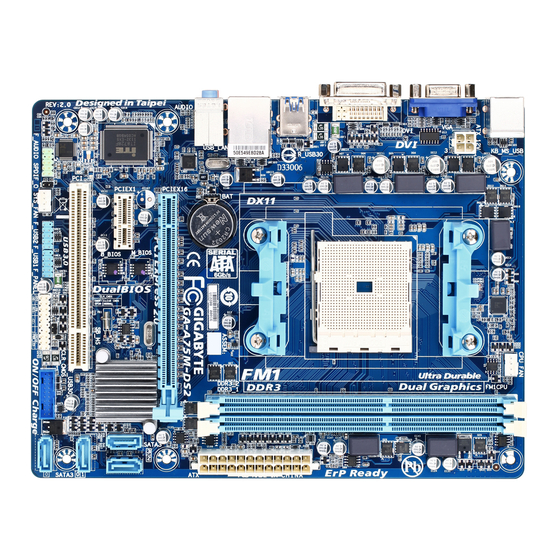
Page 6: Ga-A75M-Ds2 Motherboard Layout
GA-A75M-DS2 Motherboard Layout CPU_FAN KB_MS_USB ATX_12V Socket FM1 R_USB30 USB_LAN AUDIO Realtek GbE LAN GA-A75M-DS2 PCIEX16 SATA3 M_BIOS PCIEX1 Super AMD A75 B_BIOS SATA3 CODEC CLR_CMOS F_AUDIO SYS_FAN F_USB1 F_USB30 SPDIF_O F_USB2 F_PANEL Box Contents GA-A75M-DS2 motherboard Motherboard driver disk... -
Page 7: Ga-A75M-Ds2 Motherboard Block Diagram
GA-A75M-DS2 Motherboard Block Diagram 1 PCI Express x16 PCIe CLK AMD APU Dual Channel Memory PCI Express Bus DVI-D D-Sub 1 PCI Express x1 PCIe CLK PCI Express Bus 4 USB 3.0/2.0 8 USB 2.0/1.1 Realtek GbE Dual BIOS RJ45... -
Page 8: Chapter 1 Hardware Installation
Chapter 1 Hardware Installation Installation Precautions The motherboard contains numerous delicate electronic circuits and components which can become manual and follow these procedures: Prior to installation, make sure the chassis is suitable for the motherboard. warranty sticker provided by your dealer. These stickers are required for warranty validation. Always remove the AC power by unplugging the power cord from the power outlet before installing or removing the motherboard or other hardware components. - Page 9 FM1 Socket: AMD A series processors/AMD E2 series processors AMD Athlon ™ II series processors/AMD Sempron ™ series processors Chipset AMD A75 Memory 2 x 1.5V DDR3 DIMM sockets supporting up to 32 GB of system memory * Due to a Windows 32-bit operating system limitation, when more than 4 GB of physical the physical memory installed.
- Page 10 Internal 1 x APU fan header Connectors 1 x system fan header 1 x front panel header 1 x front panel audio header 1 x S/PDIF Out header 1 x USB 3.0/2.0 header 2 x USB 2.0/1.1 headers Back Panel 1 x PS/2 keyboard/mouse port Connectors 1 x D-Sub port...
-
Page 11: Installing The Apu
Bundled Software Operating Support for Microsoft ® Windows 8/7/Vista/XP System Form Factor Micro ATX Form Factor; 22.5cm x 17.4cm prior notice. Features" and "Bundled Software" columns. Installing the APU Read the following guidelines before you begin to install the APU: Make sure that the motherboard supports the APU. -
Page 12: Installing The Memory
Installing the Memory Read the following guidelines before you begin to install the memory: Make sure that the motherboard supports the memory. It is recommended that memory of the same capacity, brand, speed, and chips be used. Always turn off the computer and unplug the power cord from the power outlet before installing the memory to prevent hardware damage. - Page 13 Combining the onboard GPU with a discrete graphics card, AMD's Dual Graphics technology can provide Dual Graphics system. A. System Requirements - AMD A series processor - Windows 7 operating system Step 1: Observe the steps in "1-5 Installing an Expansion Card" and install an AMD Dual Graphics technology-supported graphics card on the PCIEX16 slot.
-
Page 14: Back Panel Connectors
Back Panel Connectors USB 2.0/1.1 Port PS/2 Keyboard/Mouse Port Use this port to connect a PS/2 mouse or keyboard. D-Sub Port The D-Sub port supports a 15-pin D-Sub connector. Connect a monitor that supports D-Sub connection to this port. DVI-D Port DVI-D connection to this port. -
Page 15: Internal Connectors
Internal Connectors ATX_12V F_USB30 F_USB1/F_USB2 SATA3 0/1/2/3 Read the following guidelines before connecting external devices: First make sure your devices are compliant with the connectors you wish to connect. Before installing the devices, be sure to turn off the devices and your computer. Unplug the power cord from the power outlet to prevent damage to the devices. - Page 16 With the use of the power connector, the power supply can supply enough stable power to all the components off and all devices are properly installed. The power connector possesses a foolproof design. Connect the power supply cable to the power connector in the correct orientation. The 12V power connector mainly supplies power to the APU.
- Page 17 All fan headers on this motherboard are 4-pin. Most fan headers possess a foolproof insertion design. fan with fan speed control design. For optimum heat dissipation, it is recommended that a system fan be installed inside the chassis. Pin No. CPU_FAN +12V Sense...
- Page 18 Connect the power switch, reset switch, speaker, and system status indicator on the chassis to this header according to the pin assignments below. Note the positive and negative pins before connecting the cables. Message/Power/ Power Sleep LED Switch Speaker Hard Drive Reset Power LED Activity LED...
- Page 19 your chassis front panel audio module to this header. Make sure the wire assignments of the module connector match the pin assignments of the motherboard header. Incorrect connection between the module connector and the motherboard header will make the device unable to work or even damage it. For HD Front Panel Audio: For AC'97 Front Panel Audio: Pin No.
- Page 20 optional 3.5" front panel that provides two USB 3.0/2.0 ports, please contact the local dealer. Pin No. Pin No. VBUS SSRX1- SSRX1+ SSTX2+ SSTX1- SSTX2- SSTX1+ SSRX2+ SSRX2- VBUS No Pin optional USB bracket. For purchasing the optional USB bracket, please contact the local dealer. Pin No.
- Page 21 the two pins for a few seconds. Open: Normal Short: Clear CMOS Values Always turn off your computer and unplug the power cord from the power outlet before clearing the CMOS values. in the CMOS when the computer is turned off. Replace the battery when the battery voltage drops to a low level, or the CMOS values may not be accurate or may be lost.
-
Page 22: Chapter 2 Bios Setup
To access the BIOS Setup program, press the <Delete> key during the POST when the power is turned on. To upgrade the BIOS, use either the GIGABYTE Q-Flash or @BIOS utility. Q-Flash allows the user to quickly and easily upgrade or back up BIOS without entering the operating system. -
Page 23: Startup Screen
Startup Screen The following startup Logo screen will appear when the computer boots. Function Keys Function Keys: Press the <Delete> key to enter BIOS Setup or to access the Q-Flash utility in BIOS Setup. Press the <F9> key to display your system information. arrow key <... -
Page 24: The Main Menu
The Main Menu On the main menu of the BIOS Setup program, press arrow keys to move among the items and press <Enter> to accept or enter a sub-menu. Or you can use your mouse to select the item you want. Setup Menus Enter Q-Flash Select Default... - Page 25 M.I.T. system/CPU temperatures, voltages, and fan speeds. System also displays information on the devices connected to the SATA ports. display adapter. Peripherals LAN, etc. Power Management Save all the changes made in the BIOS Setup program to the CMOS and exit BIOS Setup. You can save When the system is not stable as usual, select the Load Optimi ed Defaults item to set your system to its defaults.
-
Page 26: M.i.t
M.I.T. Whether the system will work stably with the overclock/overvoltage settings you made is dependent to CPU, chipset, or memory and reduce the useful life of these components. This page is for advanced users only and we recommend you not to alter the default settings to prevent system instability or This section provides information on the BIOS version, CPU base clock, CPU frequency, memory frequency, - 25 -... - Page 27 M.I.T. Current Status This screen provides information on CPU/memory frequencies/parameters. BCLK/PCIe Clock Control Important: It is highly recommended that the CPU frequency be set in accordance with the CPU speci cations. Processor Graphics Clock Allows you to set the CPU North Bridge frequency divisor. Displays the current operating CPU North Bridge frequency.
- Page 28 CPU Clock Ratio, CPU Frequency The settings above are synchronous to those under the same items on the Advanced Frequency Settings menu. Core Performance Boost Core Performance Boost Ratio C6 Mode Allows you to determine whether to let the CPU enter C6 mode in system halt state. When enabled, the CPU core frequency will be reduced during system halt state to decrease power consumption.
- Page 29 enabled. System Memory Multiplier Allows you to set the system memory multiplier. Auto sets memory multiplier according to memory SPD BCLK/PCIe Clock Control and System Memory Multiplier settings. , System Memory Multiplier, Memory The settings above are synchronous to those under the same items on the menu.
- Page 30 Enables or disables memory channel interleaving. Enabled allows the system to simultaneously access different channels of the memory to increase memory performance and stability. Auto lets the BIOS Enables or disables memory rank interleaving. Enabled allows the system to simultaneously access different ranks of the memory to increase memory performance and stability.
- Page 31 This sub-menu allows you to set CPU and memory voltages. PC Health Status Enabled Clears the record of previous chassis intrusion status and the "No" at next boot. - 30 -...
- Page 32 Displays the detection status of the chassis intrusion detection device attached to the motherboard CI clear the chassis intrusion status record, set to Enabled, save the settings to the CMOS, and then restart your system. CPU Vcore/Dram Voltage/+3.3V/+5V/+12V Displays the current system voltages. CPU/System Temperature Displays current CPU/system temperature.
-
Page 33: System
System This section provides information on your CPU, memory, motherboard model, and BIOS version. You can also select the default language used by the BIOS and manually set the system time. System Language Selects the default language used by the BIOS. System Date value. -
Page 34: Bios Features
submenu will be presented here. string. Or if you want to install an operating system that supports GPT partitioning such as Windows 7 64-bit, select and devices that support Boot from LAN function, etc. Press <Enter> on this item to enter the submenu that presents the devices of the same type that are connected. - Page 35 Allows you to determine whether to display the GIGABYTE Logo at system startup. Disabled skips the CSM Support Never Disables UEFI CSM and supports UEFI BIOS boot process only. Boot Mode Selection Allows you to select which type of operating system to boot.
-
Page 36: Peripherals
is enabled. is enabled. Administrator Password BIOS Setup. Differing from the user password, the administrator password allows you to make changes to all BIOS settings. User Password Setup. However, the user password only allows you to make changes to certain BIOS settings but not all. To cancel the password, press <Enter>... - Page 37 Serial ATA features such as Native Command Queuing and hot plug. If you wish to install a 3rd party add-in audio card instead of using the onboard audio, set this item to Disabled. If you wish to install a 3rd party add-in network card instead of using the onboard LAN, set this item to Disabled.
- Page 38 Integrated Graphics Enables or disables the onboard graphics function. Auto The BIOS will automatically enable or disable the onboard graphics depending on Disabled Disables the onboard graphics. Force Always activates the onboard graphics, whether or not a PCI Express card is installed.
-
Page 39: Power Management
Power Management Resume by Alarm If enabled, set the date and time as following: Wake up hour/minute/second: Set the time at which the system will be powered on automatically. Note: When using this function, avoid inadequate shutdown from the operating system or removal of the AC power, or the settings may not be effective. - Page 40 Allows the system to be turned on by a PS/2 keyboard wake-up event. Note: To use this function, you need an ATX power supply providing at least 1A on the +5VSB lead. Password Set a password with 1~5 characters to turn on the system. Keyboard 98 Press POWER button on the Windows 98 keyboard to turn on the system.
-
Page 41: Save & Exit
Press <Enter> on this item and select Yes. This saves the changes to the CMOS and exits the BIOS Setup program. Select No or press <Esc> to return to the BIOS Setup Main Menu. Press <Enter> on this item and select Yes. This exits the BIOS Setup without saving the changes made in BIOS Setup to the CMOS. -
Page 42: Chapter 3 Drivers Installation
After installing the operating system, insert the motherboard driver disk into your optical drive. The driver Autorun screen is automatically displayed which looks like that shown in the screen shot the optical drive and execute the Run After inserting the driver disk, "Xpress Install" will automatically scan your system and then list all the drivers that are recommended to install. - Page 43 refer to Chapter 2, "BIOS Setup," "Integrated Peripherals." Steps: Ensure is enabled under Peripherals. To enable RAID for the SATA2 0/1/2/3 connectors, set to RAID. 2. Save changes and exit BIOS Setup. The BIOS Setup menus described in this section may differ from the exact settings for your moth- erboard.
- Page 44 8. After the creation is complete, the screen will return to LD View Menu where you will see the newly- created array. 9. Press <Esc> to return to Main Menu and press <Esc> again if you want to exit the RAID BIOS utility. folder in the motherboard driver disk to installation.
-
Page 45: Regulatory Statements
This document must not be copied without our written permission, and the contents there of must not be believe that the information contained herein was accurate in all respects at the time of printing. GIGABYTE cannot, however, assume any responsibility for errors or omissions in this text. Also note that the information GIGABYTE. - Page 46 - 45 -...
- Page 47 - 46 -...
- Page 48 - 47 -...
- Page 49 Address: No.6, Bao Chiang Road, Hsin-Tien Dist., New Taipei City 231, Taiwan TEL: +886-2-8912-4000, FAX: +886-2-8912-4003 You may go to the GIGABYTE website, select your language in the language list on the top right corner of the website. http://ggts.gigabyte.com.tw Then select your language to enter the system.
- Page 50 GigaByte GA-A75M-DS2 rev. 3.0 Описание Характеристики...
Need help?
Do you have a question about the GA-A75M-DS2 and is the answer not in the manual?
Questions and answers