Table of Contents
Advertisement
Advertisement
Table of Contents

Related Manuals for Gigabyte GA-AB350M-D3H


Summary of Contents for Gigabyte GA-AB350M-D3H
- Page 1 GA-AB350M-D3H User's Manual Rev. 1002 12ME-AB35M3H-1002R For more product details, please visit GIGABYTE's website. To reduce the impacts on global warming, the packaging materials of this product are recyclable and reusable. GIGABYTE works with you to protect the environment.
- Page 2 The trademarks mentioned in this manual are legally registered to their respective owners. Disclaimer Information in this manual is protected by copyright laws and is the property of GIGABYTE. No part of this manual may be reproduced, copied, translated, transmitted, or published in any form or by any means without GIGABYTE's prior written permission.
-
Page 3: Table Of Contents
Table of Contents GA-AB350M-D3H Motherboard Layout ................4 Chapter 1 Hardware Installation ..................5 Installation Precautions ..................5 ..................6 Installing the CPU .................... 9 Installing the Memory ..................9 Installing an Expansion Card ................. 10 Back Panel Connectors .................. 10 Internal Connectors ..................12 Chapter 2 BIOS Setup ....................20... -
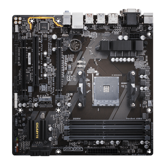
Page 4: Ga-Ab350M-D3H Motherboard Layout
GA-AB350M-D3H Motherboard Layout CPU_FAN KB_MS_USB SYS_FAN1 ATX_12V SYS_FAN2 Socket AM4 DP_HDMI USB30_LAN B_BIOS M_BIOS AUDIO GA-AB350M-D3H ® GbE LAN PCIEX16 ® Super I/O AMD B350 PCIe to CODEC PCIEX4 PCI Bridge F_USB30 SPDIF_O F_AUDIO F_USB2 F_PANEL COMA F_USB1 SYS_FAN3_PUMP Box Contents... -
Page 5: Chapter 1 Hardware Installation
Chapter 1 Hardware Installation Installation Precautions The motherboard contains numerous delicate electronic circuits and components which can become damaged as a result of electrostatic discharge (ESD). Prior to installation, carefully read the user's manual and follow these procedures: Prior to installation, make sure the chassis is suitable for the motherboard. Prior to installation, do not remove or break motherboard S/N (Serial Number) sticker or warranty sticker provided by your dealer. - Page 6 Chipset AMD B350 Memory Dual channel memory architecture (Note) non-ECC mode) (Go to GIGABYTE's website for the latest supported memory speeds and memory modules.) Onboard Integrated Graphics Processor: Graphics * The DVI-D port does not support D-Sub connection by adapter.
- Page 7 Chipset: 2 x USB 3.1 Gen 2 Type-A ports (red) on the back panel 2 x USB 3.1 Gen 1 ports (available through the internal USB header) 6 x USB 2.0/1.1 ports (2 ports on the back panel, 4 ports available through the internal USB headers) CPU: 4 x USB 3.1 Gen 1 ports on the back panel...
- Page 8 Micro ATX Form Factor; 24.4cm x 24.4cm prior notice. Please visit GIGABYTE's website Please visit the Support\Utility List for support lists of CPU, memory page on GIGABYTE's website to modules, SSDs, and M.2 devices. download the latest version of apps. - 8 -...
-
Page 9: Installing The Cpu
Make sure that the motherboard supports the memory. It is recommended that memory of the same capacity, brand, speed, and chips be used. (Go to GIGABYTE's website for the latest supported memory speeds and memory modules.) Always turn off the computer and unplug the power cord from the power outlet before installing the memory to prevent hardware damage. -
Page 10: Installing An Expansion Card
DS/SS DS/SS Two Modules DS/SS DS/SS Four Modules DS/SS DS/SS DS/SS DS/SS Due to CPU limitations, read the following guidelines before installing the memory in Dual Channel mode. Dual Channel mode cannot be enabled if only one memory module is installed. When enabling Dual Channel mode with two or four memory modules, it is recommended that memory of the same capacity, brand, speed, and chips be used. - Page 11 The line out jack. Use this audio jack for a headphone or 2-channel speaker. This jack can be used to Mic In (Pink) The Mic in jack. multi-channel audio feature through the audio driver. Please visit GIGABYTE's website for more software information. device and then remove it from the motherboard.
-
Page 12: Internal Connectors
Internal Connectors ATX_12V F_PANEL F_AUDIO CPU_FAN SYS_FAN1/2 CLR_CMOS SYS_FAN3_PUMP F_USB30 ASATA3 0/1 F_USB1/F_USB2 SATA3 0/1/2/3 M2F_32G SPDIF_O COMA First make sure your devices are compliant with the connectors you wish to connect. Before installing the devices, be sure to turn off the devices and your computer. Unplug the power cord from the power outlet to prevent damage to the devices. - Page 13 1/2) ATX_12V/ATX (2x4 12V Power Connector and 2x12 Main Power Connector) With the use of the power connector, the power supply can supply enough stable power to all the components off and all devices are properly installed. The power connector possesses a foolproof design. Connect the power supply cable to the power connector in the correct orientation.
- Page 14 5) SYS_FAN3_PUMP (System Fan/Water Cooling Pump Headers) The fan/pump headers are 4-pin. Most fan headers possess a foolproof insertion design. When connecting a fan cable, be sure to connect it in the correct orientation (the black connector wire is the ground wire). The speed control function requires the use of a fan with fan speed control design.
- Page 15 8) M2F_32G (M.2 Socket 3 Connector) through the AMD Chipset. Follow the steps below to correctly install an M.2 SSD in the M.2 connector. Step 1: Use a screw driver to unfasten the screw and nut from the motherboard. Locate the proper mounting hole Step 2: Slide the M.2 SSD into the connector at an angle.
- Page 16 9) SPDIF_O (S/PDIF Out Header) This header supports digital S/PDIF Out and connects a S/PDIF digital audio cable (provided by expansion cards) for digital audio output from your motherboard to certain expansion cards like graphics cards and sound cards. For example, some graphics cards may require you to use a S/PDIF digital audio cable for digital audio output from your motherboard to your graphics card if you wish to connect an HDMI display to the graphics card and have digital audio output from the HDMI display at the same time.
- Page 17 11) F_AUDIO (Front Panel Audio Header) your chassis front panel audio module to this header. Make sure the wire assignments of the module connector match the pin assignments of the motherboard header. Incorrect connection between the module connector and the motherboard header will make the device unable to work or even damage it. For HD Front Panel Audio: For AC'97 Front Panel Audio: Pin No.
- Page 18 13) CLR_CMOS (Clear CMOS Jumper) the CMOS values, use a metal object like a screwdriver to touch the two pins for a few seconds. Open: Normal Short: Clear CMOS Values Always turn off your computer and unplug the power cord from the power outlet before clearing the CMOS values.
- Page 19 16) TPM (Trusted Platform Module Header) You may connect a TPM (Trusted Platform Module) to this header. Pin No. Pin No. LCLK LAD0 No Pin SB3V LAD3 LAD2 VCC3 LAD1 17) LPT (Parallel Port Header) The LPT header can provide one parallel port via an optional LPT port cable. For purchasing the optional LPT port cable, please contact the local dealer.
-
Page 20: Chapter 2 Bios Setup
To access the BIOS Setup program, press the <Delete> key during the POST when the power is turned on. To upgrade the BIOS, use either the GIGABYTE Q-Flash or @BIOS utility. Q-Flash allows the user to quickly and easily upgrade or back up BIOS without entering the operating system. - Page 21 M.I.T. Whether the system will work stably with the overclock/overvoltage settings you made is dependent on your overall and reduce the useful life of these components. This page is for advanced users only and we recommend you not to alter the default settings to prevent system instability or other unexpected results. (Inadequately altering the settings may result in system's failure to boot.
- Page 22 AMD Cool&Quiet function Enabled Lets the AMD Cool'n'Quiet driver dynamically adjust the CPU clock and VID to reduce heat output from your computer and its power consumption. (Default) Disabled Disables this function. SVM Mode virtual systems. (Default: Enabled) C6 Mode (Note 1) Allows you to determine whether to let the CPU enter C6 mode in system halt state.
- Page 23 When using a non-XMP memory module or is set to Disabled, the value is set to , the value is displayed according to the SPD data on the XMP memory. Channel Interleaving Enables or disables memory channel interleaving. Enabled allows the system to simultaneously access different channels of the memory to increase memory performance and stability.
- Page 24 Smart Fan 5 Settings Monitor Allows you to select a target to monitor and to make further adjustment. (Default: CPU FAN) Fan Speed Control Allows you to determine whether to enable the fan speed control function and adjust the fan speed. Normal Allows the fan to run at different speeds according to the temperature.
-
Page 25: System
System This section provides information on your motherboard model and BIOS version. You can also select the default language used by the BIOS and manually set the system time. System Language Selects the default language used by the BIOS. System Date Sets the system date. -
Page 26: Bios
A password is required for booting the system and for entering the BIOS Setup program. (Default) Full Screen LOGO Show Allows you to determine whether to display the GIGABYTE Logo at system startup. Disabled skips the GIGABYTE Logo when the system starts up. (Default: Enabled) Fast Boot Enables or disables Fast Boot to shorten the OS boot process. - Page 27 SATA Support All Sata Devices All SATA devices are functional in the operating system and during the POST. Last Boot HDD Only Except for the previous boot drive, all SATA devices are disabled before the OS boot process completes. (Default) Fast Boot is set to Enabled or Ultra Fast.
- Page 28 Other PCI Device ROM Priority than the LAN, storage device, and graphics controllers. CSM Support is set to Enabled. Network Stack Disables or enables booting from the network to install a GPT format OS, such as installing the OS from the Windows Deployment Services server.
-
Page 29: Peripherals
Peripherals AMD CPU fTPM Enables or disables the TPM 2.0 function integrated in the AMD CPU. (Default: Disabled) Ambient LED Enables or disables the onboard audio LED. (Default: On) Legacy USB Support Allows USB keyboard/mouse to be used in MS-DOS. (Default: Enabled) XHCI Hand-off Determines whether to enable XHCI Hand-off feature for an operating system without XHCI Hand-off support. - Page 30 Trusted Computing Enables or disables Trusted Platform Module (TPM). Serial Port 1 Enables or disables the onboard serial port. (Default: Enabled) Parallel Port Enables or disables the onboard parallel port. (Default: Enabled) Displays information on your M.2 NVME PCIe SSD if installed. Displays information on your M.2 PCIe SSD if installed.
-
Page 31: Chipset
Chipset IOMMU Enables or disables AMD IOMMU support. (Default: Auto) Integrated Graphics (Note) Enables or disables the onboard graphics function. Auto The BIOS will automatically enable or disable the onboard graphics depending on the graphics card being installed. (Default) Disabled Disables the onboard graphics. -
Page 32: Power
Power AC BACK Determines the state of the system after the return of power from an AC power loss. Memory The system returns to its last known awake state upon the return of the AC power. Always On The system is turned on upon the return of the AC power. Always Off The system stays off upon the return of the AC power. - Page 33 Determines whether to let the system consume least power in S5 (shutdown) state. Note: When this item is set to Enabled up, power on by mouse, power on by keyboard, and wake on LAN. Soft-Off by PWR-BTTN Instant-Off Press the power button and then the system will be turned off instantly. (Default) Delay 4 Sec.
-
Page 34: Save & Exit
Save & Exit Save & Exit Setup Press <Enter> on this item and select Yes. This saves the changes to the CMOS and exits the BIOS Setup program. Select No or press <Esc> to return to the BIOS Setup Main Menu. Exit Without Saving Press <Enter>... -
Page 35: Chapter 3 Appendix
Chapter 3 Appendix RAID Levels RAID 0 RAID 1 RAID 10 Minimum Number of Hard Drives Array Capacity Number of hard drives * (Number of hard drives/2) * Fault Tolerance Before you begin, please prepare the following items: At least two SATA hard drives or M.2 SATA SSDs (to ensure optimal performance, it is recommended that you use two hard drives with identical model and capacity). - Page 36 4. On the Select Physical Disks to Enabled. Next, use the down arrow key to move to Apply Changes and press <Enter>. Then return to the previous screen and set the Array Size, Array Size Unit, Read Cache Policy and Write Cache Policy. 5.
-
Page 37: Drivers Installation
After installing the operating system, insert the motherboard driver disk into your optical drive. Click on install. You can click the Xpress Install the arrow icon to individually install the drivers you need. Please visit GIGABYTE's website for Please visit GIGABYTE's website more software information. software. - Page 38 Contravention will be prosecuted. We believe that the information contained herein was accurate in all respects at the time of printing. GIGABYTE cannot, however, assume any responsibility for errors or omissions in this text. Also note that the information in this document is subject to change without notice and should not be construed as a commitment by GIGABYTE.
- Page 39 FCC Notice (U.S.A. Only) This equipment has been tested and found to comply with the limits for a Class B digital device, pursuant to Part in a residential installation. This equipment generates, uses, and can radiate radio frequency energy and, if not installed and used in accordance with the instructions, may cause harmful interference to radio communications.
-
Page 40: Contact Us
Contact Us GIGA-BYTE TECHNOLOGY CO., LTD. TEL: +886-2-8912-4000, FAX: +886-2-8912-4005 Tech. and Non-Tech. Support (Sales/Marketing) : http://esupport.gigabyte.com WEB address (English): http://www.gigabyte.com WEB address (Chinese): http://www.gigabyte.tw GIGABYTE eSupport To submit a technical or non-technical (Sales/Marketing) question, please link to: http://esupport.gigabyte.com - 40 -...
Need help?
Do you have a question about the GA-AB350M-D3H and is the answer not in the manual?
Questions and answers