Table of Contents
Advertisement
Available languages
Available languages
Quick Links
CarAudio
Zusätzlich er forderliche Unterlagen für den Komplettser
Additionally r equir ed Ser vice Documents for the Complete Ser
Service
Manual
Sicherheit
Safety
Materialnr./Part No.
72010 800 0000
Btx * 32700 # • Materialnummer/Part Number 72010 760 4500
Änderungen vorbehalten/Subject to alteration • Printed in Germany
E-BS 36 1099
http://www.grundig.de
vice
vice
Service Manual
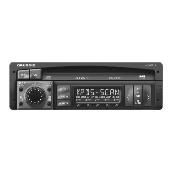
Advance CD
(G.HK 0600)
Grundig Service
Technik:
TV
TV
SAT
VCR/LiveCam
HiFi/Audio
Car Audio
Telekommunikation
Fax:
Planatron
(8.00-22.00 Uhr)
Ersatzteil-Verkauf:
Telefon:
Fax:
Hotline Deutschland...
...Mo.-Fr. 8.00-18.00 Uhr
0180/52318-41
0180/52318-49
0180/52318-48
0180/52318-42
0180/52318-43
0180/52318-44
0180/52318-45
0180/52318-51
0180/52318-99
...Mo.-Fr. 8.00-19.00 Uhr
0180/52318-40
0180/52318-50
Advertisement
Table of Contents

Related Manuals for Grundig Advance CD


Summary of Contents for Grundig Advance CD
- Page 1 Service Manual CarAudio Advance CD (G.HK 0600) Grundig Service Hotline Deutschland..Mo.-Fr. 8.00-18.00 Uhr Technik: 0180/52318-41 0180/52318-49 Zusätzlich er forderliche Unterlagen für den Komplettser vice 0180/52318-48 Additionally r equir ed Ser vice Documents for the Complete Ser vice VCR/LiveCam 0180/52318-42...
-
Page 2: Table Of Contents
Sweep Generator Stereocoder Oszilloskop Stereo Coder Oscilloscope Beachten Sie bitte das GRUNDIG Meßtechnik-Programm, das Sie Please note the Grundig Catalog "Test and Measuring Equipment" unter folgender Adresse erhalten: obtainable from: Grundig AG Geschäftsbereich Instruments Test- und Meßsysteme Würzburger Str. 150, D-90766 Fürth Tel.: 0911 / 703-4118;... -
Page 3: Ausbauhinweise
Advance CD Allgemeiner Teil / General Section Ausbauhinweise Disassembly Instructions 1. Öffnen des Gehäuses (Fig. 1) 1. Opening the Cover (Fig. 1) - Die 2 Schrauben A herausschrauben. - Undo the 2 screws A. - Den Deckel mit einem Schraubendreher an den Punkten B an- - Lift the cover with a screwdriver at the points B. - Page 4 Allgemeiner Teil / General Section Advance CD 3. Auswerfen der CD bei defektem Laufwerk 3. Removing a CD with defective Drive - Gehäuse öffnen (Pkt. 1). - Open the cover (para 1). - Das Rad F (Fig. 6) in Pfeilrichtung solange drehen, bis die CD - Turn the wheel F (Fig.
-
Page 5: Bedienhinweise
Bedienhinweise Dieses Kapitel enthält Auszüge aus der Bedienungsanleitung. Weitergehende Informationen entnehmen Sie bitte der gerätespezifischen Bedienungsanleitung, deren Materialnummer Sie in der entsprechenden Ersatzteilliste finden. Kurzanleitung Display 1. . . 5 Nummern der Stationstasten. Verstärker Programmquellen Display Radio CD-Wechsler-Betrieb NEWS . . . PTY-Funktionen. CD 1 TO 1 ¢... - Page 6 Radio Verstärker Radio Bereich gewählt: – automatisch (AUTOSCAN) Überlastungsschutz Programmquelle RADIO wählen RDS-Programme mit dem LEARN- Sender/RDS-Programme mit Suchlauf ¡ Sie hören den in diesem Bereich zuletzt ge- RADIO -Taste drücken bis der Signalton Speicher einstellen einstellen Bei hoher Umgebungstemperatur und großer Bei CD-Wechsler- oder CD-Betrieb: hörten Sender/RDS-Programm (Last-Station- erklingt.
- Page 7 Radio Radio AIM-Speicherkapazität AIM-Speicher abhören Bei AIM-Speicherbereitschaft und Autoradio ROCK M Rockmusik Programmtypen ¡ ausgeschaltet: – ca. 3 Minuten AIM TP -Taste kurz drücken; im Display … M.O.R.M Leichte Musik – Verkehrsfunk-Durchsagen, die älter als Seite 23, EXPERT-Einstellung Voraussetzung Beispiel LIGHT M Leichte klassische Musik MO7 O6: 15...
- Page 8 EXPERT CD-Betrieb Einstellungen 3. Einstellung "aktivieren" Mögliche Einstellungen Titel der CD in zufälliger Reihenfolge CD-Betrieb beenden CD ausschieben EXPERT … “ LOUD -Taste kurz drücken: (TRACK RANDOM) EXPERT ..Wählen Sie durch kurzes Drücken der Drücken Sie kurz die ¡ -Taste.
- Page 9 Codierung EXPERT Codierung Codierung Codierung aktivieren Wartezeiten AIM-TIMER 1 (Einschaltzeit 1), Wiederinbetriebnahme Codierung deaktivieren Seite 13: AIM-Funktion. Ihre persönliche Code-Nummer befindet sich 1. Expert-Mode ist eingeschaltet und Damit die "Wiederinbetriebnahme" bzw. Das Autoradio ist elektronisch blockiert, nach- Z.B. vor dem Ausbau des Autoradios: Aktuelle Uhrzeit eingestellt: oder CODE...
-
Page 10: Operating Hints
Operating Hints This chapter contains excerpts from the operating instructions. For further particulars please refer to the appropriate user instructions the part number of which is indicated in the relevant spare parts list. Brief Operating Instructions Display 1 … 5 Numbers of station buttons. - Page 11 Radio Amplifier Radio After selecting the range: – automatically (AUTOSCAN) Overload protection Selecting the RADIO programme source Setting RDS programmes with the Setting stations/RDS programmes with you will hear the station last tuned to in this ¡ Press the RADIO button until the signal LEARN memory the search function...
- Page 12 Radio Radio AIM storage capacity Listen to AIM memory If AIM memory is on and car radio is off: ROCK M Rock music Programme types (PTY) ¡ – Traffic announcements that are older than – approx. 3 minutes Press AIM TP button briefly;...
- Page 13 EXPERT CD Mode Settings 3. Activating the setting Possible settings Playing the tracks on a CD in random Terminating the CD mode Ejecting a CD EXPERT … “ LOUD Briefly press the button: order (TRACK RANDOM) EXPERT ..Select another programme source by briefly Briefly press the ¡...
- Page 14 Coding EXPERT Coding Coding Activating coding Waiting periods AIM TIMER 2 (switch-on time 2), Return to operation Deactivating coding page 13: AIM function. Your personal code number is on the identity 1. The expert mode is switched on and To prevent deactivation of the coding being The car radio is electronically disabled after it e.g., before removing the car radio: Current time is set:...
- Page 15 Advance CD Abgleichvorschriften / Adjustment Procedures Abgleichvorschriften Meßgeräte: DC-Voltmeter, Meßsender, NF-Voltmeter, Stereocoder, Wobbler, Oszilloskop Abgleich Vorbereitung Abgleichvorgang ± 1. MW Oszillator Mit L 612 (1) bei 531kHz auf 1,2V 50mV abgleichen. ± DC-Voltmeter an FMP604. Kontrolle bei 1602kHz auf 7,5V 0,5V.
-
Page 16: Adjustment Procedures
Abgleichvorschriften / Adjustment Procedures Advance CD Adjustment Procedures Test equipment: DC Voltmeter, Test Generator, AF Voltmeter, Stereo Coder, Sweep Generator, Oscilloscope Adjustment Preparation Adjustment Procedure ± 1. MW Oscillator Align with L 612 (1) at 531kHz to 1.2V 50mV. ±... - Page 17 Advance CD Abgleichvorschriften / Adjustment Procedures Abgleichlageplan Alignment Layout IC1351C R105 IC2001 F105 F101 Q201 F601 L612 L604 C607 L613 L603 C606 Meßpunkt (FMP...) Abgleichpunkt Test Point (FMP...) Adjustment Point Zum Abgleich die Antennennachbildungen für AM bzw. FM verwenden. For adjustment use the aerial dummies for AM resp. FM.
- Page 18 Abgleichvorschriften / Adjustment Procedures Advance CD 2. Parametertabelle / Set of Parameters Parameter Wert Beschreibung Parameter Wert Beschreibung Value Description Value Description Suchlauf-Schwelle / Search Level 0004 Suchlauf-Schwelle / Search Level 0010 1520 0040 2280 0004 2000 0020 1600 0050...
-
Page 19: Circuit Diagrams And Layout Of The Pcbs
Advance CD Schaltpläne und Druckplattenabbildungen / Circuit Diagrams and Layout of the PCBs Advance CD Schaltpläne und Druckplattenabbildungen / Circuit Diagrams and Layout of the PCBs Schaltpläne und Druckplattenabbildungen / Circuit Diagrams and Layout of the PCBs Bauteilhinweise / Hints on Components... -
Page 20: Rf Part
Schaltpläne und Druckplattenabbildungen / Circuit Diagrams and Layout of the PCBs Advance CD Schaltpläne und Druckplattenabbildungen / Circuit Diagrams and Layout of the PCBs Advance CD HF-Teil / RF Part MISCHTEIL CT102 MIXER SECTION FM-ZF-TEIL BC848C CC08 FM-IF SECTION CT01... - Page 21 Advance CD Schaltpläne und Druckplattenabbildungen / Circuit Diagrams and Layout of the PCBs Advance CD Schaltpläne und Druckplattenabbildungen / Circuit Diagrams and Layout of the PCBs STEREO / VSA / KLANGSTELLER CR216 CR217 UREF CR119 MPX-MUTE K-SIG C202 C201 MPX1...
-
Page 22: Prozessor-Teil
Schaltpläne und Druckplattenabbildungen / Circuit Diagrams and Layout of the PCBs Advance CD Schaltpläne und Druckplattenabbildungen / Circuit Diagrams and Layout of the PCBs Advance CD Prozessor-Teil / Processor Part 5V-REFERENZ 5V REFERENCE CR808 CR801 CR805P CR809 CL801 CIC2051 10UH... - Page 23 Advance CD Schaltpläne und Druckplattenabbildungen / Circuit Diagrams and Layout of the PCBs Advance CD Schaltpläne und Druckplattenabbildungen / Circuit Diagrams and Layout of the PCBs UMSCHALTUNG RT/GN TASTEN CT2371 D2351 BC808/40 R2376 5V-GESCHALTET 5V SWITCHED CR2375M 1N4001 CR2370N CR2377...
-
Page 24: Lcd Board
Schaltpläne und Druckplattenabbildungen / Circuit Diagrams and Layout of the PCBs Advance CD Schaltpläne und Druckplattenabbildungen / Circuit Diagrams and Layout of the PCBs Advance CD LCD-Platte / LCD Board ALLE SPANNUNGEN SIND NÄHERUNGSWERTE, GEMESSEN BEI UB=14V GEGEN MINUS DISPLAYBELEUCHTUNG... -
Page 25: Operating Board
Advance CD Schaltpläne und Druckplattenabbildungen / Circuit Diagrams and Layout of the PCBs Advance CD Schaltpläne und Druckplattenabbildungen / Circuit Diagrams and Layout of the PCBs Bedien-Platte / Operating Board TASTEN-BELEUCHTUNG INKREMENTENGEB.BEL. TREBLE CS1007 BALANCE LOUD CS1006 EXPERT BU1001 TAS-RT... -
Page 26: Aim-Platte
Schaltpläne und Druckplattenabbildungen / Circuit Diagrams and Layout of the PCBs Advance CD Schaltpläne und Druckplattenabbildungen / Circuit Diagrams and Layout of the PCBs Advance CD AIM-Platte / AIM Board 4MHz EOS-AIM Q2501 WR-AIM -RESET Q2502 RD-AIM CR2531 WRITE S-5V... -
Page 27: Cd-Teil
Advance CD Schaltpläne und Druckplattenabbildungen / Circuit Diagrams and Layout of the PCBs Advance CD Schaltpläne und Druckplattenabbildungen / Circuit Diagrams and Layout of the PCBs CD-Teil / CD Part 13V9 SONY CD-LAUFWERK CMX-205A INSW IC1351C GND (A) 7805 RECHTS... -
Page 28: Af Part
Schaltpläne und Druckplattenabbildungen / Circuit Diagrams and Layout of the PCBs Advance CD Schaltpläne und Druckplattenabbildungen / Circuit Diagrams and Layout of the PCBs Advance CD NF-Teil / AF Part ALLE SPANNUNGEN SIND NÄHERUNGSWERTE, GEMESSEN BEI UB=14V GEGEN MINUS ALL VOLTAGES ARE APPROXIMATES, MEASURED AT UB=14V WITH RESPECT TO NEGATIV... - Page 29 Advance CD Schaltpläne und Druckplattenabbildungen / Circuit Diagrams and Layout of the PCBs Advance CD Schaltpläne und Druckplattenabbildungen / Circuit Diagrams and Layout of the PCBs ENDSTUFEN (FRONT) FMP1606 POWER AMPLIFIER FMP1607 VCC1 VCC2 OPA1 FMP1608 OUT1 FMP1609 C1601 CR1541...
-
Page 30: Connecting Board
Schaltpläne und Druckplattenabbildungen / Circuit Diagrams and Layout of the PCBs Advance CD Schaltpläne und Druckplattenabbildungen / Circuit Diagrams and Layout of the PCBs Advance CD Anschluß-Platte / Connecting Board II-5 II-6 KAMMER I LINE-RL TEL NF II-3 LINE-RR TEL GND... - Page 31 Advance CD Schaltpläne und Druckplattenabbildungen / Circuit Diagrams and Layout of the PCBs Advance CD Schaltpläne und Druckplattenabbildungen / Circuit Diagrams and Layout of the PCBs Bauteil / CC1527 CR21 CT2081V Hauptplatte / Main Board Component CC1554S CR2109 CT2082V CC1566S...
- Page 32 Schaltpläne und Druckplattenabbildungen / Circuit Diagrams and Layout of the PCBs Advance CD Schaltpläne und Druckplattenabbildungen / Circuit Diagrams and Layout of the PCBs Advance CD Bauteil / F104 Hauptplatte / Main Board Component F105 F601 Bedrahtete Bauteile - Ansicht von der Lötseite / Wired Components - View of Solder Side...
- Page 33 Advance CD Schaltpläne und Druckplattenabbildungen / Circuit Diagrams and Layout of the PCBs Advance CD Schaltpläne und Druckplattenabbildungen / Circuit Diagrams and Layout of the PCBs Bauteil / CC1548 CR801 CR1571S Hauptplatte / Main Board Component CC1549 CR802C CR1572S CC1557S...
-
Page 34: Lcd Board
Schaltpläne und Druckplattenabbildungen / Circuit Diagrams and Layout of the PCBs Advance CD Schaltpläne und Druckplattenabbildungen / Circuit Diagrams and Layout of the PCBs Advance CD Bedien-Platte / Operating Board AIM-Platte / AIM Board Anschluß-Platte / Connecting Board Ansicht von der Bestückungsseite / View of Component Side Ansicht von der Bestückungsseite / View of Component Side... -
Page 35: G.hk
CL 00606 81405 264 7500 SMD DR 1206 8,2UH 10% AV2 72011 828 9900 ADVANCE CD TAUSCHGERAET ADVANCE CD EXCHANGE SET CD 00803 83093 890 7000 SMD-Z DIODE Z 47 SB14125 CL 00701 81405 264 6900 SMD DR 1206 0,1UH 20% AV2... - Page 36 POS. NR. MATERIAL-NR. BEZEICHNUNG POS. NR. MATERIAL-NR. BEZEICHNUNG POS. NO. PART NUMBER DESCRIPTION POS. NO. PART NUMBER DESCRIPTION CT 02102 83010 068 1800 SMD-TRANS.BC 818-40 S8 CT 02103 83023 661 4400 SMD-TRANS.DTC 144 EK CT 02201 83013 751 1400 SMD TRANS.DTC 114 EK CT 02202 83023 681 1400 SMD TRANS DTC114YK CT 02301...
Need help?
Do you have a question about the Advance CD and is the answer not in the manual?
Questions and answers