
Related Manuals for Toshiba SD-V55HTSU


Summary of Contents for Toshiba SD-V55HTSU
-
Page 1: Home Theater System
FILE NO. 810-200425 SERVICE MANUAL DVD/VCR Home Theater System SD-V55HTSU SD-V55HTSC DOCUMENT CREATED IN JAPAN, May, 2004... - Page 2 CONTENTS SECTION 1 ..SUMMARY SECTION 2 ..CABINET & MAIN CHASSIS SECTION 3 ..ELECTRICAL SECTION 4 ..MECHANISM OF VCR PART SECTION 5 ..MECHANISM OF DVD PART SECTION 6 .
-
Page 3: Table Of Contents
SECTION 1 SUMMARY CONTENTS PRODUCT SAFETY SERVICING GUIDELINES FOR VIDEO PRODUCTS ..... 1-2 SERVICING PRECAUTIONS ....................1-3 • General Servicing Precautions • Insulation Checking Prodedure • Electrostatically Sensitive(ES) Devices OWNER’S MANUAL(SD-V55HTSU) ..................1-5... -
Page 4: Product Safety Servicing Guidelines For Video Products
When servicing this product, under no circumstances should the original design be modified or altered without permission from TOSHIBA Electronics Corporation. All components should be replaced only with types identical to those in the original circuit and their physical location, wiring and lead dress must conform to original layout upon completion of repairs. -
Page 5: Servicing Precautions
SERVICING PRECAUTIONS CAUTION: Before servicing the COMBI HOME THEATER Electrostatically Sensitive (ES) Devices SYSTEM covered by this service data and its supplements Some semiconductor (solid state) devices can be damaged and addends, read and follow the SAFETY PRECAUTIONS. easily by static electricity. Such components commonly are NOTE: if unforeseen circumstances create conflict between called Electrostatically Sensitive (ES) Devices. -
Page 6: Owner's Manual(Sd-V55Htsu)
DVD/VCR Home Theater System SD-V55HTSU OWNER’S MANUAL Before connecting, operating or adjusting this product, please read this instruction booklet carefully and completely. ©2004 Toshiba Corporation This device does not tape-record copy protected DVD Video Discs. -
Page 7: Safety Precautions
Safety Precautions CAUTION: The apparatus should not be exposed to water CAUTION (dripping or splashing) and no objects filled with liquids, such as vases, should be placed on the apparatus. RISK OF ELECTRIC SHOCK DO NOT OPEN FCC WARNING: This equipment may generate or use radio frequency energy. -
Page 8: Important Safety Instructions
IMPORTANT SAFETY INSTRUCTIONS CAUTION: PLEASE READ AND OBSERVE ALL WARNINGS AND INSTRUCTIONS IN THIS OWNER’S MANUAL. AND THOSE MARKED ON THE PRODUCT. RETAIN THIS BOOKLET FOR FUTURE REFERENCE. This product has been designed and manufactured to assure personal safety. Improper use can result in electric shock or fire hazard. -
Page 9: Table Of Contents
Table of Contents Introduction Search....... 31 Random......31 Safety Precautions. -
Page 10: Before Use
Before Use Playable Discs Disc-related Terms Title (DVD only) The main film content or accompanying feature content (8 cm/12 cm disc) or additional feature content, or music album. Each title is assigned a title reference number enabling Video CD (VCD) you to locate it easily. -
Page 11: Precautions
Before Use (Continued) Precautions Cleaning discs Fingerprints and dust on the disc can cause poor pic- Handling the unit ture quality and sound distortion. Before playing, clean the disc with a clean cloth. Wipe the disc from the cen- When shipping the unit ter out. -
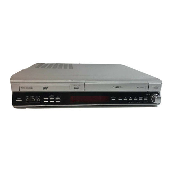
Page 12: Front Panel
Front Panel EJECT POWER Ejects the tape in the VCR deck. Switches the DVD/VCR Receiver ON and OFF. VIDEO / AUDIO (Left/Right) input VOLUME Connect the audio/video output of an Adjusts volume of speakers. external source (Audio system, TV/ Monitor, another VCR). -
Page 13: Display Window
Display Window Indicates encoding format of the current disc. A cassette is in the VCR deck. RADIO Indicates RADIO mode is active MUTE The speaker sound is muted. Indicates sound mode is DOLBY PROLOGIC or DOLBY PROLOGICII. SAP Indicates when a SAP BILINGUAL broadcast is being received. -
Page 14: Remote Control
Remote Control TV POWER POWER Switches TV ON and OFF. Switches DVD/VCR Receiver ON and OFF. INPUT - Selects the VCR deck’s source (Tuner, LINE 1, or LINE 2). To control multi-brand TV. - Selects the TV external source. DVD/CD To control DVD/CD operating. -
Page 15: Rear Panel
Rear Panel VCR IN LINE 1 (VIDEO IN/AUDIO IN (Left/Right)) DVD/VCR OUT (VIDEO/AUDIO (Left/Right)) Connect the audio/video output of an external Connect to a TV with video and audio inputs. source (Audio system, TV/Monitor, Another VCR). COMPONENT/PROGRESSIVE SCAN VIDEO OUT (Y Pb Pr) (DVD OUT) Connect to a TV with Y Pb Pr inputs. -
Page 16: Connections
Connections Without Cable Box If your cable wire is connected to your TV without a converter Depending on your TV and other equipment you wish to or descrambler box, unscrew the wire from your TV and attach it to the ANT.IN jack on the DVD/VCR Receiver. Use the sup- connect, there are various ways you could connect the plied round coaxial cable to connect between the DVD/VCR DVD/VCR Receiver. -
Page 17: Basic Tv Connections
Connections (Continued) Basic TV Connections Optional TV Connections Make one of the following connections, depending on the capabilities of your TV. DVD playback can also be done using the S-VIDEO OUT RF coaxial connection and COMPONENT/PROGRESSIVE SCAN VIDEO OUT Connect the RF.OUT jack on the DVD/VCR Receiver to connection options below. -
Page 18: Speaker System Connections
Connections (Continued) Speaker System Connections Speaker Positioning Connect the speakers using the supplied speaker cords For a normal setup use 6 speakers (2 front speakers, by matching the colors of the terminals and those of the center speaker, 2 rear speakers and subwoofer). cords. -
Page 19: Radio Antenna Connections
Connections (Continued) Radio Antenna Connections Digital Device Connections Connect the DIGITAL AUDIO IN (OPTICAL) jacks on Connect the supplied FM/AM antennas for radio listen- the DVD/VCR Receiver to the digital audio out (optical) ing. jacks on your digital device (Game device, Digital Set Connect the AM loop antenna to the AM antenna Top Box, etc.), using optional optical audio cable. -
Page 20: Selecting The Input/Output Source
Selecting the Input/Output Source Follow these guidelines to select and switch among the DVD/CD FM/AM various DVD/VCR Receiver input and output sources: • DVD/CD To view output from the DVD deck: Press DVD/CD on the remote or DVD/VCR on the front panel until the DVD indicator on the front panel lights and output from the DVD deck is viewed on the TV screen. -
Page 21: Before Operation - Sound Mode Descriptions
Before Operation - Sound Mode Descriptions Mini Glossary for Audio Stream & BYPASS Software with multichannel surround audio signals is played Surround mode according to the way it was recorded. Sound Mode (DTS) Allows you to enjoy 5.1(or 6) discrete channels of high quality You can enjoy surround sound simply by selecting one digital audio from DTS program sources such as discs, DVD of the pre-programmed sound fields according to the... -
Page 22: Vcr Operation Setup
VCR Operation Setup On-Screen Display (OSD) EASY INFORMATION If the Extended Data Service (XDS) signals are provided Set the Output Source to VCR as shown in “Selecting along with normal TV signal in your area or during play- the Input/Output Source” on page 15. back of a tape recorded with Extended Data Service (XDS) signals, the station ID, program title, and program Some of these functions appear during VCR operated. -
Page 23: Vcr Setup Menu Options
VCR Operation Setup (Continued) VCR Setup Menu Options Channel Selection This DVD/VCR Receiver is equipped with a Press MENU and the MAIN menu will appear. frequency synthesized tuner capable of receiving up to 181 channels. These include VHF channels 2-13, UHF Use v v /V V to select the SETUP menu, then press channels 14-69 and CATV channels 1-125. -
Page 24: Setting The Clock
VCR Operation Setup (Continued) Setting the Clock There are cases where the TV station does not send or sends The DVD/VCR Receiver gives you two ways to set the the wrong time. Therefore, the incorrect time will be set. If this time and date: the Auto Clock Feature or manually. -
Page 25: Dvd Operation Setup
DVD Operation Setup General Explanation Temporary Feedback Field Icons This manual gives basic instructions for operating the Repeat Title TITLE DVD/VCR Receiver. Some DVDs require specific opera- Repeat Chapter tion or allow only limited operation during playback. CHAPT When this occurs, the symbol appears on the TV Repeat Track (non-PBC Video CDs TRACK... -
Page 26: Initial Settings
DVD Operation Setup (Continued) Initial Settings Picture TV Aspect You can set your personal preferences on the DVD/VCR Receiver. 4:3 Letterbox: Select when a standard 4:3 TV is con- nected. Displays pictures with masking bars above and General Operation below the picture. Press SETUP. -
Page 27: Speaker Setup
DVD Operation Setup (Continued) Speaker setup Auto Play You can set up the DVD Player so a DVD disc automat- 5.1 Speaker settings ically starts playing whenever the DVD is inserted. Select speaker settings, including volume balance and If Auto Play mode is set to On, this DVD player will distance, or test the speaker settings. -
Page 28: Parental Control
DVD Operation Setup (Continued) Parental Control Area Code Enter the code of a country/area whose standards were Rating used to rate the DVD video disc, referring to the list Movies on DVDs may contain scenes not suitable for (See “Country/Area Code List”, page 45). children. -
Page 29: Vcr Operation
VCR Operation Normal Playback Special Effect Playbacks Preparation: Special effects playback notes Turn on the TV. Horizontal lines (noise bars) will appear on the TV screen. Tune the TV to the DVD/VCR Receiver output channel (CH This is normal. 3 or 4) or set the TV’s source selector to VIDEO. The audio is automatically muted during special effect modes, If a direct VIDEO/AUDIO connection is made between the so there is no sound during search. -
Page 30: Normal Recording
VCR Operation (Continued) Normal Recording Timer Recording Preparation: This DVD/VCR Receiver can be programmed to record Turn on the power of both the DVD/VCR Receiver and TV. up to 8 programs within a period of 1 year. For unattend- Tune the TV to the DVD/VCR Receiver output channel (CH 3 ed recording, the timer needs to know the channels to be or 4) or set the TV’s source selector to VIDEO. - Page 31 VCR Operation (Continued) 1 1 0 0 Use V V to choose the SPEED option. otes Use b b /B B to choose the desired recording If the power fails or the DVD/VCR Receiver is unplugged speed (AUTO, SP or SLP). from the AC outlet, the correct clock time and timer settings AUTO mode determines how much tape is left and are kept in memory for approximately 3 seconds.
-
Page 32: Instant Timer Recording
VCR Operation (Continued) Instant Timer Recording Dubbing and Editing If you wish to edit or dub your camcorder (or another Instant Timer Recording allows you to make a recording VCR) recordings to this DVD/VCR Receiver, the rear easily of a preset length without using the programma- (or Front) panel mounted Audio and Video (A/V) input ble timer. -
Page 33: Vhs Hi-Fi Stereo System/Mts Broadcast
VCR Operation (Continued) VHS Hi-Fi Stereo System/ MTS (Multi-Channel TV Sound) MTS Broadcast This DVD/VCR Receiver will decode MTS stereo and bilingual (SAP) off-the-air broadcast sound signals. It This DVD/VCR Receiver is equipped with the VHS Hi-Fi also decodes stereo TV sound from local cable compa- audio sound system for recording and playback. -
Page 34: Tape Counter Memory Feature
VCR Operation (Continued) Tape Counter Memory Feature Additional Information Real-Time Counter In manual recording, Timer recording, Instant Timer Recording, playback, or fast forward modes, the DVD/VCR Shows length of tape run in hours, minutes, and Receiver automatically starts rewinding the tape at the end seconds. -
Page 35: Dvd And Video Cd Operation
DVD and Video CD Operation Playing DVD and Video CD General Features Playback Setup VCD2.0 VCD1.1 Unless stated otherwise, all operations described use the remote control. Some features may also be Turn on the TV and select the video input source connected available on the Setup menu. -
Page 36: Search
DVD and Video CD Operation (Continued) General Features (Continued) Repeat A-B VCD2.0 VCD1.1 Search VCD2.0 VCD1.1 To repeat a sequence in a title: 1 Press and hold SKIP . or > for about two sec- 1 Press A-B at your chosen start point. onds during playback. -
Page 37: Marker Search
DVD and Video CD Operation (Continued) General Features (Continued) Special DVD Features Checking the contents of DVD Video Marker Search VCD2.0 VCD1.1 discs: Menus MARKER SEARCH DVDs may contain menus that allow you to access spe- You can start playback from a memorized point. Up to cial features. -
Page 38: Audio Cd And Mp3/Wma Disc Operation
Audio CD and MP3/WMA Disc Operation Playing an Audio CDs and MP3/WMA otes on MP3/WMA Recordings Discs About MP3 An MP3 file is audio data compressed by using the The DVD/VCR Receiver can play MP3/WMA formatted MPEG1 audio layer-3 file-coding scheme. We call recordings on CD-ROM, CD-R or CD-RW discs. -
Page 39: Pause
Audio CD and MP3/WMA Disc Operation (Continued) Pause Repeat A-B 1 Press PAUSE/STEP during playback. To repeat a sequence. 2 To return to playback, press PLAY or press 1 During disc playback, press A-B at your chosen start- PAUSE/STEP again. ing point. -
Page 40: Jpeg File Operation
JPEG File Operation Selecting other Files Viewing JPEG Files on a Disc JPEG Press SKIP . or > once while viewing a picture to This DVD/VCR Receiver can play discs with JPEG files. advance to the next file or to the previous file. Before playing JPEG files, read the notes on JPEG Still Picture Files on right. -
Page 41: Programmed Playback
Programmed Playback VCD2.0 VCD1.1 Programmed Playback with Audio CDs Insert Video CD and close the tray. and MP3/WMA Discs Press PROGRAM while playback is stopped. The VCD Program menu will appear. The Program function enables you to store your Program favourite tracks from any disc in the player memory. -
Page 42: Speaker Setup
Speaker Setup Adjust the following settings for the built-in 5.1 channel Distance surround decoder. If you connected speakers to your DVD/VCR Receiver , setting the Distance lets the speakers know how far the Disc Audio sound has to travel to reach your set listening point. Disc Subtitle This allows the sound from each speaker to reach the Disc Menu... -
Page 43: Radio Operation
Radio Operation Presetting the Radio Stations Listening to the Radio You can preset 50 stations for FM and AM. Before tun- Preset radio stations in the DVD/VCR Receiver memory ing, make sure that you have turned down the volume. first (see “Presetting Radio Stations” on the left). Press FM/AM on the remote control or RADIO Press FM/AM on the remote control or RADIO on the front panel until the frequency band... -
Page 44: Tuning Into A Station Manually
Radio Operation (Continued) Tuning into a Station Manually Press FM/AM on the remote control until the fre- quency band appears on the display and TV screen. Press FM/AM on the remote control to select the desired band. Press TUNING (4 4 /3 3 ) on the remote control to tune in the desired station. -
Page 45: Controlling Your Tv With The Supplied Remote
The remote control can be compatible with various brands of TV by setting their control codes. The TOSHI- TV POWER BA code has initially been set to control TOSHIBA TVs. Setting TV Control Codes INPUT 1. Press TV to set the remote control operating your TV. -
Page 46: Controlling Your Tv With The Supplied Remote
Controlling Your TV with the Supplied Remote (Continued) Table of TV Brand Codes Brand name of your TV Brand Code Brand name of your TV Brand Code Runco (NEC) Toshiba Bell & Howell Samsung 11,12 Carver Sanyo Celebrity Scotch Citizen... -
Page 47: Troubleshooting
Troubleshooting Check the following guide for the possible cause of a problem before contacting service. Cause Solution Symptom The power cord is disconnected. Plug the power cord into the wall outlet No power. securely. No disc is inserted. Insert a disc or tape. (Check that the The power is on, but the DVD/VCR Receiver No tape is inserted. -
Page 48: Troubleshooting
Troubleshooting (Continued) Cause Solution Symptom INPUT, VOLUME Incorrect mode (e.g. Remote control in Press DVD/CD, VCR or FM/AM to buttons on TV mode). select the correct mode on the remote b/B/v/V control. remote control cannot operate. Some channels are Those channels were deleted with the Use CH. -
Page 49: Language Code List
Language Code List Enter the appropriate code number for the initial settings “Disc Audio”, “Disc Subtitle” and/or “Disc Menu” (See page 21). Code Language Code Language Code Language Code Language 6566 Abkhazian 7074 Fiji 7678 Lingala 8373 Singhalese 6565 Afar 7073 Finnish 7684... -
Page 50: Country/Area Code List
Country/Area Code List Enter the appropriate code number for the initial setting “Area Code List” (See page 23). Code Country Code Country Code Country Code Country Andorra Eritrea Saint Lucia Seychelles United Arab Emirates Spain Liechtenstein Sudan Afghanistan Ethiopia Sri Lanka Sweden Antigua and Barbuda Finland... -
Page 51: Specifications
Specifications General Power requirements AC 120V, 60 Hz Power consumption Dimensions (approx.) 430 X 81 X 380 mm (17 x 3.2 x 14.9 inches) (w x h x d) Mass (approx.) 6 kg (13.2 lbs) Operating temperature 5˚C to 35˚C (41˚F to 95˚F) Operating humidity 5 % to 90 % Signal system... - Page 52 Specifications (Continued) FM Tuner Tuning Range 87.5 - 108.0 MHz Intermediate Frequency 10.7 MHz AM Tuner Tuning Range 530 - 1,720 kHz Intermediate Frequency 450 kHz Amplifier Stereo mode 60W + 60W (8Ω at 1 kHz, THD 10 %) Surround mode Front: 60W + 60W (8Ω...
-
Page 53: Limited Warranty Dvd Players/Recorders
Limited Warranty DVD Players/Recorders Toshiba America Consumer Products, L.L.C. (“TACP”) makes the following limited warranties to original consumers in the United States. THESE LIMITED WARRANTIES EXTEND TO THE ORIGINAL CONSUMER PURCHASER OR ANY PERSON RECEIVING THIS DVD Player/Recorder AS A GIFT FROM THE ORIGINAL CONSUMER PUR- CHASER AND TO NO OTHER PURCHASER OR TRANSFEREE. - Page 54 STANCES. charges for the DVD PLAYER/RECORDER to the Service Station. For additional information, visit TACP’s web site: www.tacp.toshiba.com Time for Taking Action ALL WARRANTIES IMPLIED BY THE LAW OF ANY STATE OF THE U.S.A., INCLUDING THE IMPLIED WARRANTIES OF MERCHANTABILITY AND FITNESS...
- Page 55 P/NO: 3834RH0033S 1-54...
- Page 56 SECTION 2 CABINET & MAIN CHASSIS CONTENTS EXPLODED VIEWS ........................2-2 1. Cabinet and Main Frame Section ...................2-2 2. Woofer Speaker Section (V55HTW) ..................2-3 3. Speaker Center Section (V55HTC) ..................2-4 4. Speaker Rear/Front Section (V55HTS) ..................2-4 5. Packing Accessory Section ....................2-5...
-
Page 57: Exploded Views
EXPLODED VIEWS 1. Cabinet and Main Frame Section... -
Page 58: Woofer Speaker Section (V55Htw)
2. Woofer Speaker Section (V55HTW) A900... -
Page 59: Speaker Center Section (V55Htc)
3. Speaker Center Section (V55HTC) A700... -
Page 60: Speaker Rear/Front Section (V55Hts)
4. Speaker Rear/Front Section (V55HTS) A800... -
Page 61: Packing Accessory Section
5. Packing Accessory Section CABLE SET ASS'Y, RF PLUG ASS'Y 1WAY(YELLOW) CABLE, COAXIAL CABLE, COAXIAL PLUG ASS'Y 2WAY 824 ANTENNA LOOP(AM) 825 ANTENNA (FM) BATTERY OWNER'S MANUAL REMOCON PACKING, CASING 803A PACKING, CASING 803B 803C PACKING, CASING SHEET PACKING, CASING OPTIONAL PARTS... - Page 62 SECTION 4 MECHANISM OF VCR PART(D-37) CONTENTS POSITION DRAWING OF DECK DECK MECHANISM ADJUSTMENT MECHANISM PARTS • Fixtures and tools for service ....4-12 1. Mechanism Assembly Mode Check ..4-13 • Top View............4-1 2. Previous Preparation for • Bottom View ..........4-1 Deck Adjustment ........4-14 3.
- Page 63 POSITION DRAWING OF DECK MECHANISM PARTS • Top View Order Of Dis- Ref. Posi assembled Part Fixing Type Draw- tion Parts firstly ings Disassembled 1 Drum Assembly 3 screws 2 Plate Top 2 hooks 3 Holder Assembly CST 6 chasses 4 Gear Assembly Rack F/L 1 hook 2,3,4...
- Page 64 DISASSEMBLY AND ASSEMBLY OF DECK MECHANISM Drum Assembly Cable Flat (S1) (S1) (S1) Cap, FPC Holder FPC Fig. A-1 Cautions in assembly of FPC 1. Disassembly of Drum Assembly (Figure A-1) 1) Separate cable flat from the Drum FPC and the Capstan Motor.
- Page 65 DISASSEMBLY AND ASSEMBLY OF DECK MECHANISM Plate Top (Fig. A-2-1) (B') Holder Assembly CST (Fig. A-2-2) Arm Assembly F/L (Fig. A-2-5) Lever Assembly S/W (Fig. A-2-6) (H4) Opener Door (Fig. A-2-4) (H3) Gear Assembly Rack F/L (Fig. A-2-3) Fig. A-2...
- Page 66 DISASSEMBLY AND ASSEMBLY OF DECK MECHANISM 2. Disassembly of Plate Top (Fig. A-2-1) 4. Disassembly of Gear Assembly Rack F/L (Fig. A-2-3) 1) Separate the right part while leaning back the (B) part of 1) Separate the hook (H3) while leaning ahead the hook (3) the plate top toward the arrow direction.
- Page 67 DISASSEMBLY AND ASSEMBLY OF DECK MECHANISM Arm Assembly Cleaner (Fig. A-3-3) (H5) Gear Wheel (Fig. A-3-2) Base Assembly A/C Head Motor Assembly L/D (S5) (Fig. A-3-5) (Fig. A-3-1) Head F/E (C1) (Fig. A-3-4) (S4) Fig. A-3 8. Motor Assembly L/D (Fig. A-3-1) 10.
- Page 68 DISASSEMBLY AND ASSEMBLY OF DECK MECHANISM Arm Assembly Tension (Fig. A-4-2) (H7) Reel T (Fig. A-4-3) Reel S (Fig. A-4-3) Spring Tension Brake Assembly T Spring Tension (Fig. A-4-1) (H8) (H6) Fig. A-4 13. Brake Assembly T (Fig. A-4-1) 15. Reel S/Reel T (Fig. A-4-3) 1) Release the spring tension from the lever spring hook 1) Disassemble the reel S/ reel T while holding it up (com- (H6).
- Page 69 DISASSEMBLY AND ASSEMBLY OF DECK MECHANISM Opener Lid (Fig. A-5-2) Arm Assembly Pinch (Fig. A-5-3) Base Assembly P4 (Fig. A-5-1) (H9) Arm T/up (Fig. A-5-4) Chassis Fig. A-5 16. Base Assembly P4 (Fig. A-5-1) 18. Arm Assembly Pinch (Fig. A-5-3) 1) Release the (A) part of the base assembly P4 from the 1) Hold the arm assembly pinch up.
- Page 70 DISASSEMBLY AND ASSEMBLY OF DECK MECHANISM Suppoter Capstan (Fig. A-6-1) Belt Capstan (Fig. A-6-2) Motor Capstan (Fig. A-6-3) Washer(W1) Clutch Assembly D37 (Fig. A-6-5) (L1) (L1) Lever F/R (Fig. A-6-4) Chassis (S6) Fig. A-6 20. Supporter, Capstan (Fig. A-6-1) 22. Lever F/R (Fig. A-6-4) 1) Turn the supporter and Capstan by 90 deg.
- Page 71 DISASSEMBLY AND ASSEMBLY OF DECK MECHANISM (H10) (H11) Gear Sector Gear Cam (Fig. A-7-3) (Fig. A-7-2) (W2) Washer (W2) Brake Assembly Capstan Gear Cam Hole(B) (Fig. A-7-4) Plate Slider (L2) Gear Drive (Fig. A-7-5) (Fig. A-7-1) Gear Drive Hole(A) Lever Tension (Fig.
- Page 72 DECK MECHANISM DISASSEMBLY Gear assembly P2 Hole Gear assembly P3 Hole Gear Assembly P3 (Fig. A-8-2) Gear Assembly P2 (Fig. A-8-1) (H13) (H12) Lever Tension Boss Plate slider Hole(B) (H14) Base Loading (Fig. A-8-5) Chassis Base Assembly P3 (Fig. A-8-4) Base Assembly P2 (Fig.
- Page 73 DISASSEMBLY AND ASSEMBLY OF DECK MECHANISM Base Tension (Fig. A-9-1) Arm Assembly Idler Jog (Fig. A-9-2) Chassis Fig. A-9 34. Base Tension (Fig. A-9-1) 35. Arm assembly Idler Jog (Fig. A-9-2) 1) Release the (A) part of the base tension from the 1) Push both (B), (C) parts in Fig.
-
Page 74: Deck Mechanism Adjustment
DECK MECHANISM ADJUSTMENT • Fixtures and Tools for Service 1. Cassette Torque Meter 2. Alignment tape 3. Torque gauge SRK-VHT-303(Not SVC part) Part No NTSC:DTN-0001 600g.Cm ATG Part No:D00-D006 PAL:DTN-0002 Part No:D00-D002 4. Torque gauge adaptor 5. Post height adjusting driver 6. - Page 75 DECK MECHANISM ADJUSTMENT 1. Mechanism Assembly Mode Check Purpose of adjustment : To make tools normally operate by positioning tools accurately. Fixtures and tools used VCR (VCP) status Checking Position • Eject Mode • Blank Tape (empty tape) • Mechanism and Mode Switch (with cassette withdrawn) 1) Turn the VCR on and take the tape out by pressing the 4) Undo the screw fixing the deck and the main frame, and...
- Page 76 DECK MECHANISM ADJUSTMENT 2. Previous Preparation for Deck Adjustment (Preparation to load the VCR (VCP) with cassette tape not inserted) 1) Take the power cord from the consent. If doing so, proceeding to the stop mode is done. In this 2) Separate the top cover and the plate assembly top.
-
Page 77: Guide Roller Height Adjustment
DECK MECHANISM ADJUSTMENT 4. Guide Roller Height Adjustment Purpose of adjustment : To ensure that the bottom surface of the tape can travel along with the tape lead line of the lower drum by constantly and adjusting and maintaining the height of the tape. 4-1. - Page 78 DECK MECHANISM ADJUSTMENT 5. Audio/Control (A/C) Head Adjustment Purpose of adjustment : To ensure that audio and control signals can be recorded and played according to the contract tract by constantly maintaining distance between tape and head, and tape tension between the P3 post and the P4 post.
- Page 79 DECK MECHANISM ADJUSTMENT 5-2. Tape Path Check between Pinch Roller and travel it stably to ensure there is no crumbling or fold- ing of the tape. Take up Guide (Check in the Rev Mode) 1) Check the tape pass status between the pinch roller and 2) Check there is folding of the tape at the bottom or top the take-up guide.(Check there is crumpling of the tape of the take-up guide in cutting-off the REV mode...
- Page 80 DECK MECHANISM ADJUSTMENT 7. Adjustment after Drum Assembly (Video Heads) Purpose of adjustment : To adjust and stabilize the height change, X-distance change, etc depending on the guide roller after assembling the drum. Fixtures and tools used Connection position VCR (VCP) status Adjustment position •...
- Page 81 PROTECTION, MAINTENANCE AND CHECK OF VIDEO FUNCTION 1. Checking Points prior to Repair Following abnormal phenomena may be repaired by removal of foreign materials and oil supply. Check oiling is required at the checking set or cleaning status is complete. Determine that necessity of checking and repair the set exists after checking the using period of the set together with the user.
- Page 82 PROTECTION, MAINTENANCE AND CHECK OF VIDEO FUNCTION 2. Essential Check and Repair 4. Tools for Check and Repair Recording density of the video is far higher than the audio. (1) Grease: Floil G-3114 (KANTO) or equivalent grease Therefore video parts are very precise so as to allow only (Green) error of 1/1000mm or so in order to maintain compatibility (2) Grease: Kanto G-754, PL-433 (Yellow)
- Page 83 PROTECTION, MAINTENANCE AND CHECK OF VIDEO FUNCTION 5-2) Grease Applications (2) Regular Grease Application Apply grease to the designated application position (1) Grease Application Method every 500 hour. Apply grease by using a cloth swab or brush. Care must be exercised so that excess quantity should not be used.
- Page 84 PROTECTION, MAINTENANCE AND CHECK OF VIDEO FUNCTION Lever, F/R, Base, Tension GEAR AY, P2 & P3 PL-433 LEVER, F/R BASE, TENSION Clutch Contact Part (PL-433, Yellow) Tension Arm Party Hinge Part (PL-433, Yellow) 4-22...
-
Page 85: Deck Mechanism
MECHANISM TROUBLESHOOTING GUIDE 1.Deck Mechanism No Auto Rewind operates. Is output of the end sensor “H”? “H”: 3.5V or less “L”: 0.7V –1V or less Is the end sensor Vcc applied at Check the Syscon power supply. Replace the end sensor. Is voltage at both ends of the Replace the LED. - Page 86 MECHANISM TROUBLESHOOTING GUIDE Auto Stop operates. (PLAY/CUE/REV) Check the assembly mode. Check the spring pinch. Does the pinch roller attached to the Capstan shaft turn in opera- Is output of the DFG, DPG Replace the drum motor. tion of the Play/Cue/Rev. normal? Does the T/UP or the supply Check the Servo, Syscon.
- Page 87 MECHANISM TROUBLESHOOTING GUIDE No tape winding is done in play. Is the pinch roller attached to the Check the assembly mode? Capstan shaft in operation of play? Does the T/up reel operate? Is the Capstan belt hung? Hang the Capstan belt. Check the clutch and the idler Does the Capstan motor turn? assembly.
-
Page 88: Front Loading Mechanism
MECHANISM TROUBLESHOOTING GUIDE 2. Front Loading Mechanism No cassette insert is done. Does the lever assembly Is the lever assembly switch Add or replace the lever switch operate? spring normal? assembly switches spring. Does the CST IN switch Replace the F/L switch. operate normally? Is the Vcc of the main P.C.B assembly? - Page 89 MECHANISM TROUBLESHOOTING GUIDE No safe adherence of tape is done. Is cassette insert done? Does the opener lid operate? Replace the opener lid. Does the gear rack F/L operate? Replace the gear rack F/L. Does the opener door operate? Check the assembly status of the Does the arm assembly F/L operate? opener door.
- Page 90 EXPLODED VIEWS 1. Front Loading Mechanism Section 4-28...
- Page 91 EXPLODED VIEWS 2. Moving Mechanism Section (1) OPTIONAL PART 4-29...
- Page 92 EXPLODED VIEWS 3. Moving Mechanism Section (2) 4-30...
- Page 94 SECTION 5 MECHANISM OF DVD PART CONTENTS 5. Frame Assembly Up/Down ....5-4 DECK MECHANISM PARTS 6. Belt Loading........5-4 LOCATION 7. Gear Pulley ........5-4 8. Gear Loading ........5-4 • Top View(with Tray) .......5-1 9. Guide Up/Down.........5-4 • Top View(without Tray) ......5-1 •...
-
Page 95: Deck Mechanism Parts Location
DECK MECHANISM PARTS LOCATION • Top View (With Tray) Procedure Disass Fig- Parts Fixing Type embly Starting No. Holder 2 Screws, Clamp 2 Locking Tabs Clamp Assembly Disc 1, 2 Plate Clamp 1, 2, 3 Magnet Clamp 1, 2, 3, 4 Clamp Upper Tray Disc 1, 6... -
Page 96: Deck Mechanism Disassembly
DECK MECHANISM DISASSEMBLY Fig. 5-1 Fig. 5-2 1. Holder Clamp (Fig. 5-1) 2. Tray Disc (Fig. 5-2) 1) Release 2 Screws(S1). 1) Insert and push a Driver in the emergency eject 2) Unhook 2 Locking Tabs(L1). hole(A) at the right side, or put the Driver on the 3) Lift up the Holder Clamp and then separate it from the Lever(B) of the Gear Emergency and pull the Lever(B) Base Main. -
Page 97: Base Assembly Sled
DECK MECHANISM DISASSEMBLY Fig. 5-3 3. Base Assembly Sled (Fig. 5-3) 3-3. Gear Assembly Rack 1) Release the Scerw(S3) 1) Release 4 Screw(S2). 2) Disconnect the FFC Connector(C1) 4. Rubber Rear (Fig. 5-3) 3-1. Gear Assembly Feed 3-2. Gear Middle... -
Page 98: Frame Assembly Up/Down
DECK MECHANISM DISASSEMBLY Fig. 5-4 5. Frame Assembly Up/Down (Fig. 5-4) 8. Gear Loading (Fig. 5-4) 9. Guide Up/Down (Fig. 5-4) Note 1) Move the Guide Up/Down in direction of arrow(A) as Put the Base Main face down(Bottom Side) Fig.(A) 1) Release the Screw(S4) 2) Push the Locking Tab(L5) down and then lift up the 2) Unlock the Locking Tab(L3) in direction of arrow and... -
Page 100: Exploded View
EXPLODED VIEW 1. Deck Mechanism Exploded View 024A 024B 024A 011A 015A 015B 015C... - Page 102 NOTES) electricial shock. SECTION 6 REPLACEMENT PARTS LIST TOSHIBA MODEL : SD-V55HTSC NSP : Not avallable as service parts. RUN DATE : 27-APRIL-04 S AL LOCA. NO. TOSHIBA P/N. PART NO. DESCRIPTION SPECIFICATION REMARKS *** INDIVIDUAL PARTS *** AF000545 255-249C PLATE JACK GND (OC 3800"S)
- Page 103 S AL LOCA. NO. TOSHIBA P/N. PART NO. DESCRIPTION SPECIFICATION REMARKS AF000552 3140R-H003A CHASSIS COMBI-81MM PRESS MAIN 79097906 353-051B SCREW,DRAWING SPECIAL *** DECK ASSEMBLY , VIDEO (DVD) *** AF000643 6721RF0379A DECK ASSEMBLY,VIDEO DECK/MECHA DP-7C SLIM (DI) 79096511 4861R-0016C CLAMP ASSEMBLY...
- Page 104 S AL LOCA. NO. TOSHIBA P/N. PART NO. DESCRIPTION SPECIFICATION REMARKS AF000600 4930R-0376A HOLDER DECK/MECHA FPCB(6CH) - D35S, D AF000611 5006R-0042A DECK/MECHA FPCB - D35S, D37V O AF000056 4580R-0004A ROLLER CLEANER AF000376 4260R-0053A DECK/MECHA CLEANER MOLD - D37 AF000473 6850R-HG18Y CABLE,FLAT P=1.25 FFC UL2896(0.05X0.8) 7...
- Page 105 S AL LOCA. NO. TOSHIBA P/N. PART NO. DESCRIPTION SPECIFICATION REMARKS AF000592 4510R-0060A LEVER DECK/MECHA SWITCH(V) OTHER - D AF000423 4970R-0163A SPRING COIL D35S SWITCH AF000329 1MPC0301499 SCREW MACHINE,PAN HEAD D3.0 L4.0 SWRCH18A/FZY 79096381 1MEC0302018 PAN HEAD MACHINE SCREW S/W + D 3.0...
- Page 106 S AL LOCA. NO. TOSHIBA P/N. PART NO. DESCRIPTION SPECIFICATION REMARKS D125 79096001 0DD010009AC DIODE,RECTIFIERS EU01W(R-FORM) TP SANKEN D126 AF000598 4811R-0043R BRACKET ASSEMBLY F20U20S_HEAT SINK (DI) D126 AF000517 0DRFC00171A DIODE,RECTIFIERS FFPF20U20STU FAIR CHILD ST TO2 D127 AF000596 4811R-0043P BRACKET ASSEMBLY...
- Page 107 S AL LOCA. NO. TOSHIBA P/N. PART NO. DESCRIPTION SPECIFICATION REMARKS T102 AF000619 6170RNGW16C TRANSFORMER,SMPS[COIL] EER3530 SOOJUNG 580UH TH01 AF000626 6322B62204A THERMISTOR,PTC NTPAN4R0LDRB0 MURATA 4.0OHM 15 V101 79098795 656-004C VARISTOR,DRAWING SVC681D-10A SAMHWA 4.O CUT ZD101 AF000521 0DZ472609AB DIODE,ZENERS UZ-4.7BSB PYUNG CHANG TP DO34...
- Page 108 S AL LOCA. NO. TOSHIBA P/N. PART NO. DESCRIPTION SPECIFICATION REMARKS C336 79096281 0CH1103K516 CHIP CAPA CERAMIC M/L H.D F/S 0.01U 50V K B 2.0X1.25 R/TP C337 79096281 0CH1103K516 CHIP CAPA CERAMIC M/L H.D F/S 0.01U 50V K B 2.0X1.25 R/TP...
- Page 109 S AL LOCA. NO. TOSHIBA P/N. PART NO. DESCRIPTION SPECIFICATION REMARKS C578 79098709 0CE2274C638 CAPACITOR,ELECTROLYTIC 220M SRA 6.3V M FM5 TP(5) C579 79098709 0CE2274C638 CAPACITOR,ELECTROLYTIC 220M SRA 6.3V M FM5 TP(5) C580 79096286 0CH1223K516 CAPA,CHIP CERAMIC M/L H.D F/S 0.022U 50V K B 2.0X1.2 R/TP...
- Page 110 S AL LOCA. NO. TOSHIBA P/N. PART NO. DESCRIPTION SPECIFICATION REMARKS C834 79096289 0CH1472K516 CAPA,CHIP CERAMIC M/L H.D F/S 4700P 50V K B 2.0*1.25 R/TP C836 79096281 0CH1103K516 CHIP CAPA CERAMIC M/L H.D F/S 0.01U 50V K B 2.0X1.25 R/TP...
- Page 111 S AL LOCA. NO. TOSHIBA P/N. PART NO. DESCRIPTION SPECIFICATION REMARKS IC504 79096322 0IKE703100A IC,KEC KIA7031P 3P 3.1V RESET(TAPING) IC505 79098739 0IKE704200B IC,KEC KIA7042P 3P 4.2V RESET(TAPING) IC506 79097140 0IFA742440F IC,FAIRCHILD MM74HCT244SJ 20P SOIC TP 3-STA IC602 79096330 0IPRPMT006A IC,PERIPHERALS...
- Page 112 S AL LOCA. NO. TOSHIBA P/N. PART NO. DESCRIPTION SPECIFICATION REMARKS R183 79096344 0RH1001D622 RESISTOR,METAL GLAZED(CHIP) 1K OHM 1 / 10 W 2012 5.00% D R301 79096345 0RH1002D622 RESISTOR,METAL GLAZED(CHIP) 10K OHM 1 / 10 W 2012 5.00% D R302...
- Page 113 S AL LOCA. NO. TOSHIBA P/N. PART NO. DESCRIPTION SPECIFICATION REMARKS R529 79096345 0RH1002D622 RESISTOR,METAL GLAZED(CHIP) 10K OHM 1 / 10 W 2012 5.00% D R530 79096206 0RH0000D622 RESISTOR,METAL GLAZED(CHIP) 0 OHM 1 / 10 W 2012 5.00% D R531...
- Page 114 S AL LOCA. NO. TOSHIBA P/N. PART NO. DESCRIPTION SPECIFICATION REMARKS R628 79096343 0RH0752D622 RESISTOR,METAL GLAZED(CHIP) 75 OHM 1 / 10 W 2012 5.00% D R702 79096344 0RH1001D622 RESISTOR,METAL GLAZED(CHIP) 1K OHM 1 / 10 W 2012 5.00% D R703...
- Page 115 S AL LOCA. NO. TOSHIBA P/N. PART NO. DESCRIPTION SPECIFICATION REMARKS C604 79098728 0CN1040K948 CAPACITOR,FIXED TUBULAR(HIGH D 0.1UF D 50V 80%,-20% F(Y5V) TA C606 79098728 0CN1040K948 CAPACITOR,FIXED TUBULAR(HIGH D 0.1UF D 50V 80%,-20% F(Y5V) TA C609 790971234 0CN1020K518 CAPACITOR TUBULA(HIGH DIELE)
- Page 116 S AL LOCA. NO. TOSHIBA P/N. PART NO. DESCRIPTION SPECIFICATION REMARKS SW601 79097338 556-219B SWITCH,TACT THVV502GAA POSTECH DC 12 V 5- SW602 79097338 556-219B SWITCH,TACT THVV502GAA POSTECH DC 12 V 5- SW603 79097338 556-219B SWITCH,TACT THVV502GAA POSTECH DC 12 V 5-...
- Page 117 S AL LOCA. NO. TOSHIBA P/N. PART NO. DESCRIPTION SPECIFICATION REMARKS C220 AF000270 0CH1104K512 CAPACITOR,FIXED CERAMIC(Temp.c 0.1UF 50V 10% B(5YP) 1608 R/TP C221 79097104 0CE1064F638 CAPACITOR,ELECTROLYTIC 10M SRA 16V M FM5 TP(5) C222 79097104 0CE1064F638 CAPACITOR,ELECTROLYTIC 10M SRA 16V M FM5 TP(5)
- Page 118 S AL LOCA. NO. TOSHIBA P/N. PART NO. DESCRIPTION SPECIFICATION REMARKS C365 79096142 0CE4766F618 CAPACITOR,ELECTROLYTIC 47M SMS 16V M FL TP(5) C366 AF000270 0CH1104K512 CAPACITOR,FIXED CERAMIC(Temp.c 0.1UF 50V 10% B(5YP) 1608 R/TP C367 79096126 0CE1076F618 CAPACITOR,ELECTROLYTIC 100M SMS 16V M FM5 TP(5)
- Page 119 S AL LOCA. NO. TOSHIBA P/N. PART NO. DESCRIPTION SPECIFICATION REMARKS C496 AF000270 0CH1104K512 CAPACITOR,FIXED CERAMIC(Temp.c 0.1UF 50V 10% B(5YP) 1608 R/TP C497 AF000270 0CH1104K512 CAPACITOR,FIXED CERAMIC(Temp.c 0.1UF 50V 10% B(5YP) 1608 R/TP C498 AF000270 0CH1104K512 CAPACITOR,FIXED CERAMIC(Temp.c 0.1UF 50V 10% B(5YP) 1608 R/TP...
- Page 120 S AL LOCA. NO. TOSHIBA P/N. PART NO. DESCRIPTION SPECIFICATION REMARKS C568 79092025 0CH4221K412 CAPACITOR,CHIP[CERAMIC M/L TC 220P 50V J COG 1.6X0.8 R/TP C569 79092025 0CH4221K412 CAPACITOR,CHIP[CERAMIC M/L TC 220P 50V J COG 1.6X0.8 R/TP C571 AF000270 0CH1104K512 CAPACITOR,FIXED CERAMIC(Temp.c 0.1UF 50V 10% B(5YP) 1608 R/TP...
- Page 121 S AL LOCA. NO. TOSHIBA P/N. PART NO. DESCRIPTION SPECIFICATION REMARKS C726 AF000499 0CE107BK618 CAPACITOR,FIXED ELECTROLYTIC 100UF KME TYPE 50V 20% FL TP 5 C727 AF000510 0CH4331K416 CAPACITOR,CHIP[CERAMIC M/L TC 330P 50V J NP0 2.0X1.2 R/TP C728 79096149 0CH1104K566 CAPACITOR,FIXED CERAMIC(TEMP.C 0.1UF 2012 50V 10% X7R(X) R/TP...
- Page 122 S AL LOCA. NO. TOSHIBA P/N. PART NO. DESCRIPTION SPECIFICATION REMARKS C831 79096164 0CQ1041N409 CAPACITOR,FIXED FILM 0.1UF D 100V 5% PE TP5 C832 79096164 0CQ1041N409 CAPACITOR,FIXED FILM 0.1UF D 100V 5% PE TP5 C833 79096169 0CQ4742L439 CAPACITOR,FIXED FILM 0.47UF S 63V 5% M/PE NI TP5...
- Page 123 S AL LOCA. NO. TOSHIBA P/N. PART NO. DESCRIPTION SPECIFICATION REMARKS L464 79091005 6200HJC102A FILTER(CIRC),EMC HB-1M2012-102JT CERATECH TP L465 79091005 6200HJC102A FILTER(CIRC),EMC HB-1M2012-102JT CERATECH TP L501 79091005 6200HJC102A FILTER(CIRC),EMC HB-1M2012-102JT CERATECH TP L502 79091005 6200HJC102A FILTER(CIRC),EMC HB-1M2012-102JT CERATECH TP L503...
- Page 124 S AL LOCA. NO. TOSHIBA P/N. PART NO. DESCRIPTION SPECIFICATION REMARKS R137 79093027 0RH1000C622 RESISTOR,METAL GLAZED(CHIP) 100 OHM 1 / 16 W 1608 5.00% D R138 79093027 0RH1000C622 RESISTOR,METAL GLAZED(CHIP) 100 OHM 1 / 16 W 1608 5.00% D R139...
- Page 125 S AL LOCA. NO. TOSHIBA P/N. PART NO. DESCRIPTION SPECIFICATION REMARKS R228 79096030 0RH1003C622 RESISTOR,METAL GLAZED(CHIP) 100K OHM 1 / 16 W 1608 5.00% D R229 79093035 0RH1502C622 RESISTOR,METAL GLAZED(CHIP) 15K OHM 1 / 16 W 1608 5.00% D R230...
- Page 126 S AL LOCA. NO. TOSHIBA P/N. PART NO. DESCRIPTION SPECIFICATION REMARKS R364 79098770 0RH1801C622 RESISTOR,METAL GLAZED(CHIP) 1.8K OHM 1 / 16 W 1608 5.00% D R365 79098770 0RH1801C622 RESISTOR,METAL GLAZED(CHIP) 1.8K OHM 1 / 16 W 1608 5.00% D R366...
- Page 127 S AL LOCA. NO. TOSHIBA P/N. PART NO. DESCRIPTION SPECIFICATION REMARKS R476 79093045 0RH4701C622 RESISTOR,METAL GLAZED(CHIP) 4.7K OHM 1 / 16 W 1608 5.00% D R478 79093045 0RH4701C622 RESISTOR,METAL GLAZED(CHIP) 4.7K OHM 1 / 16 W 1608 5.00% D R479...
- Page 128 S AL LOCA. NO. TOSHIBA P/N. PART NO. DESCRIPTION SPECIFICATION REMARKS R576 79093044 0RH4700C622 RESISTOR,METAL GLAZED(CHIP) 470 OHM 1 / 16 W 1608 5.00% D R577 79093044 0RH4700C622 RESISTOR,METAL GLAZED(CHIP) 470 OHM 1 / 16 W 1608 5.00% D R578...
- Page 129 S AL LOCA. NO. TOSHIBA P/N. PART NO. DESCRIPTION SPECIFICATION REMARKS R750 AF000538 0RJ0151D672 RESISTOR,METAL GLAZED(CHIP) 1.5 OHM 1/10 W 5% 2012 R/TP R751 79098771 0RH2200C622 RESISTOR,METAL GLAZED(CHIP) 220 OHM 1 / 16 W 1608 5.00% D R752 79093020 0RH0000C622 RESISTOR,METAL GLAZED(CHIP) 0 OHM 1 / 16 W 1608 5.00% D...
- Page 130 S AL LOCA. NO. TOSHIBA P/N. PART NO. DESCRIPTION SPECIFICATION REMARKS AF000568 353M050C SCREW,DRAWING BH 3.5X16 FBK AF000629 6400WETN01A SPEAKER,WOOFER 18P90EHC1391 EAW WOOFER 4 OHM AF000548 3091RMW108A CABINET ASSEMBLY SPK LHS-C444W WOOD AF000654 6871RU5776A PWB(PCB) ASSEMBLY,SUBSET(AUDIO DTE-606W AA6ELL9 MOLD,ROUND 54...
- Page 131 6-30...
- Page 132 NOTES) electricial shock. SECTION 6 REPLACEMENT PARTS LIST TOSHIBA MODEL : SD-V55HTSU NSP : Not avallable as service parts. RUN DATE : 27-APRIL-04 S AL LOCA. NO. TOSHIBA P/N. PART NO. DESCRIPTION SPECIFICATION REMARKS *** INDIVIDUAL PARTS *** AF000545 255-249C PLATE JACK GND (OC 3800"S)
- Page 133 S AL LOCA. NO. TOSHIBA P/N. PART NO. DESCRIPTION SPECIFICATION REMARKS AF000562 3508R-H007A DECORATION COMBI-TOSHIBA MOLD AF000585 3790R-P088A WINDOW,DECO HOME COMBI-TOSHIBA MOLD DISPLA *** DECK ASSEMBLY , VIDEO (DVD) *** AF000643 6721RF0379A DECK ASSEMBLY,VIDEO DECK/MECHA DP-7C SLIM (DI) 79096511 4861R-0016C...
- Page 134 S AL LOCA. NO. TOSHIBA P/N. PART NO. DESCRIPTION SPECIFICATION REMARKS AF000562 3508R-H007A DECORATION COMBI-TOSHIBA MOLD AF000585 3790R-P088A WINDOW,DECO HOME COMBI-TOSHIBA MOLD DISPLA *** DECK ASSEMBLY , VIDEO (DVD) *** AF000643 6721RF0379A DECK ASSEMBLY,VIDEO DECK/MECHA DP-7C SLIM (DI) 79096511 4861R-0016C...
- Page 135 S AL LOCA. NO. TOSHIBA P/N. PART NO. DESCRIPTION SPECIFICATION REMARKS AF000592 4510R-0060A LEVER DECK/MECHA SWITCH(V) OTHER - D AF000423 4970R-0163A SPRING COIL D35S SWITCH AF000329 1MPC0301499 SCREW MACHINE,PAN HEAD D3.0 L4.0 SWRCH18A/FZY 79096381 1MEC0302018 PAN HEAD MACHINE SCREW S/W + D 3.0...
- Page 136 S AL LOCA. NO. TOSHIBA P/N. PART NO. DESCRIPTION SPECIFICATION REMARKS D126 AF000598 4811R-0043R BRACKET ASSEMBLY F20U20S_HEAT SINK (DI) D126 AF000517 0DRFC00171A DIODE,RECTIFIERS FFPF20U20STU FAIR CHILD ST TO2 D127 AF000596 4811R-0043P BRACKET ASSEMBLY FMB-G24H_HEAT SINK (DI) D127 AF000515 0DR104510AB DIODE,RECTIFIERS...
- Page 137 S AL LOCA. NO. TOSHIBA P/N. PART NO. DESCRIPTION SPECIFICATION REMARKS TH01 AF000626 6322B62204A THERMISTOR,PTC NTPAN4R0LDRB0 MURATA 4.0OHM 15 V101 79098795 656-004C VARISTOR,DRAWING SVC681D-10A SAMHWA 4.O CUT ZD101 AF000521 0DZ472609AB DIODE,ZENERS UZ-4.7BSB PYUNG CHANG TP DO34 ZD102 79096311 0DZ102609BB DIODE,ZENER...
- Page 138 S AL LOCA. NO. TOSHIBA P/N. PART NO. DESCRIPTION SPECIFICATION REMARKS C338 79096283 0CH1104K946 CAPACITOR,FIXED CERAMIC(TEMP.C 0.1UF 2012 50V 80%,-20% Y5V(F) C339 79097108 0CE4764F638 CAPACITOR,ELECTROLYTIC 47M SRA/SS 16V M FM5 TP(5) C340 79098702 0CE1054K638 CAPACITOR,ELECTROLYTIC 1.0M SRA/SS50V M FM5 TP(5)
- Page 139 S AL LOCA. NO. TOSHIBA P/N. PART NO. DESCRIPTION SPECIFICATION REMARKS C580 79096286 0CH1223K516 CAPA,CHIP CERAMIC M/L H.D F/S 0.022U 50V K B 2.0X1.2 R/TP C581 79096281 0CH1103K516 CHIP CAPA CERAMIC M/L H.D F/S 0.01U 50V K B 2.0X1.25 R/TP...
- Page 140 S AL LOCA. NO. TOSHIBA P/N. PART NO. DESCRIPTION SPECIFICATION REMARKS C838 79096283 0CH1104K946 CAPACITOR,FIXED CERAMIC(TEMP.C 0.1UF 2012 50V 80%,-20% Y5V(F) C839 79096275 0CE4754K638 CAPACITOR,FIXED ELECTROLYTIC 4.7UF SRA,SS 50V 20% FM5 TP 5 C840 79097104 0CE1064F638 CAPACITOR,ELECTROLYTIC 10M SRA 16V M FM5 TP(5)
- Page 141 S AL LOCA. NO. TOSHIBA P/N. PART NO. DESCRIPTION SPECIFICATION REMARKS IC506 79097140 0IFA742440F IC,FAIRCHILD MM74HCT244SJ 20P SOIC TP 3-STA IC602 79096330 0IPRPMT006A IC,PERIPHERALS MM1225XFBE MITSUMI 8PIN SOP R/ IC801 AF000297 0ILNRSA013B IC,LINEAR LA72670BM-L-MPB-E SANYO 80PIN JK801 AF000637 6612JH003DA JACK,RCA...
- Page 142 S AL LOCA. NO. TOSHIBA P/N. PART NO. DESCRIPTION SPECIFICATION REMARKS R302 79096359 0RH2702D622 RESISTOR,METAL GLAZED(CHIP) 27K OHM 1 / 10 W 2012 5.00% D R303 79096344 0RH1001D622 RESISTOR,METAL GLAZED(CHIP) 1K OHM 1 / 10 W 2012 5.00% D R304...
- Page 143 S AL LOCA. NO. TOSHIBA P/N. PART NO. DESCRIPTION SPECIFICATION REMARKS R531 79096365 0RH4701D622 RESISTOR,METAL GLAZED(CHIP) 4.7K OHM 1 / 10 W 2012 5.00% D R533 79096345 0RH1002D622 RESISTOR,METAL GLAZED(CHIP) 10K OHM 1 / 10 W 2012 5.00% D R534...
- Page 144 S AL LOCA. NO. TOSHIBA P/N. PART NO. DESCRIPTION SPECIFICATION REMARKS R703 79096362 0RH3901D622 RESISTOR,METAL GLAZED(CHIP) 3.9K OHM 1 / 10 W 2012 5.00% D R706 79096369 0RH6800D622 RESISTOR,METAL GLAZED(CHIP) 680 OHM 1 / 10 W 2012 5.00% D R707...
- Page 145 S AL LOCA. NO. TOSHIBA P/N. PART NO. DESCRIPTION SPECIFICATION REMARKS C609 790971234 0CN1020K518 CAPACITOR TUBULA(HIGH DIELE) 1000P 50V TA26 C609 79097123 0CN1020K518 CAPACITOR TUBULA(HIGH DIELE) 1000P 50V TA26 C610 790971234 0CN1020K518 CAPACITOR TUBULA(HIGH DIELE) 1000P 50V TA26 C610 79097123...
- Page 146 S AL LOCA. NO. TOSHIBA P/N. PART NO. DESCRIPTION SPECIFICATION REMARKS SW603 79097338 556-219B SWITCH,TACT THVV502GAA POSTECH DC 12 V 5- SW604 79097338 556-219B SWITCH,TACT THVV502GAA POSTECH DC 12 V 5- SW605 79097338 556-219B SWITCH,TACT THVV502GAA POSTECH DC 12 V 5-...
- Page 147 S AL LOCA. NO. TOSHIBA P/N. PART NO. DESCRIPTION SPECIFICATION REMARKS C222 79097104 0CE1064F638 CAPACITOR,ELECTROLYTIC 10M SRA 16V M FM5 TP(5) C223 79096142 0CE4766F618 CAPACITOR,ELECTROLYTIC 47M SMS 16V M FL TP(5) C224 79096272 0CE3354K638 CAPACITOR,FIXED ELECTROLYTIC 3.3UF SRA,SS 50V 20% FM5 TP 5...
- Page 148 S AL LOCA. NO. TOSHIBA P/N. PART NO. DESCRIPTION SPECIFICATION REMARKS C367 79096126 0CE1076F618 CAPACITOR,ELECTROLYTIC 100M SMS 16V M FM5 TP(5) C368 79097104 0CE1064F638 CAPACITOR,ELECTROLYTIC 10M SRA 16V M FM5 TP(5) C369 79097104 0CE1064F638 CAPACITOR,ELECTROLYTIC 10M SRA 16V M FM5 TP(5)
- Page 149 S AL LOCA. NO. TOSHIBA P/N. PART NO. DESCRIPTION SPECIFICATION REMARKS C498 AF000270 0CH1104K512 CAPACITOR,FIXED CERAMIC(Temp.c 0.1UF 50V 10% B(5YP) 1608 R/TP C499 AF000270 0CH1104K512 CAPACITOR,FIXED CERAMIC(Temp.c 0.1UF 50V 10% B(5YP) 1608 R/TP C502 79092013 0CH1103K562 CAPACITOR,FIXED CERAMIC(TEMP.C 0.01UF 50V 10% X7R(X) 1608 R/T...
- Page 150 S AL LOCA. NO. TOSHIBA P/N. PART NO. DESCRIPTION SPECIFICATION REMARKS C571 AF000270 0CH1104K512 CAPACITOR,FIXED CERAMIC(Temp.c 0.1UF 50V 10% B(5YP) 1608 R/TP C572 AF000270 0CH1104K512 CAPACITOR,FIXED CERAMIC(Temp.c 0.1UF 50V 10% B(5YP) 1608 R/TP C573 79098709 0CE2274C638 CAPACITOR,ELECTROLYTIC 220M SRA 6.3V M FM5 TP(5)
- Page 151 S AL LOCA. NO. TOSHIBA P/N. PART NO. DESCRIPTION SPECIFICATION REMARKS C728 79096149 0CH1104K566 CAPACITOR,FIXED CERAMIC(TEMP.C 0.1UF 2012 50V 10% X7R(X) R/TP C729 79096149 0CH1104K566 CAPACITOR,FIXED CERAMIC(TEMP.C 0.1UF 2012 50V 10% X7R(X) R/TP C730 79096149 0CH1104K566 CAPACITOR,FIXED CERAMIC(TEMP.C 0.1UF 2012 50V 10% X7R(X) R/TP...
- Page 152 S AL LOCA. NO. TOSHIBA P/N. PART NO. DESCRIPTION SPECIFICATION REMARKS C833 79096169 0CQ4742L439 CAPACITOR,FIXED FILM 0.47UF S 63V 5% M/PE NI TP5 C841 79096164 0CQ1041N409 CAPACITOR,FIXED FILM 0.1UF D 100V 5% PE TP5 C842 79096164 0CQ1041N409 CAPACITOR,FIXED FILM 0.1UF D 100V 5% PE TP5...
- Page 153 S AL LOCA. NO. TOSHIBA P/N. PART NO. DESCRIPTION SPECIFICATION REMARKS L501 79091005 6200HJC102A FILTER(CIRC),EMC HB-1M2012-102JT CERATECH TP L502 79091005 6200HJC102A FILTER(CIRC),EMC HB-1M2012-102JT CERATECH TP L503 79091005 6200HJC102A FILTER(CIRC),EMC HB-1M2012-102JT CERATECH TP L504 79091005 6200HJC102A FILTER(CIRC),EMC HB-1M2012-102JT CERATECH TP L505...
- Page 154 S AL LOCA. NO. TOSHIBA P/N. PART NO. DESCRIPTION SPECIFICATION REMARKS R139 79093027 0RH1000C622 RESISTOR,METAL GLAZED(CHIP) 100 OHM 1 / 16 W 1608 5.00% D R140 79093027 0RH1000C622 RESISTOR,METAL GLAZED(CHIP) 100 OHM 1 / 16 W 1608 5.00% D R141...
- Page 155 S AL LOCA. NO. TOSHIBA P/N. PART NO. DESCRIPTION SPECIFICATION REMARKS R230 79093051 0RH7501C622 RESISTOR,METAL GLAZED(CHIP) 7.5K OHM 1 / 16 W 1608 5.00% D R231 79093057 0RH1500C622 RESISTOR,METAL GLAZED(CHIP) 150 OHM 1 / 16 W 1608 5.00% D R232...
- Page 156 S AL LOCA. NO. TOSHIBA P/N. PART NO. DESCRIPTION SPECIFICATION REMARKS R366 79098770 0RH1801C622 RESISTOR,METAL GLAZED(CHIP) 1.8K OHM 1 / 16 W 1608 5.00% D R367 79098773 0RH4702C622 RESISTOR,METAL GLAZED(CHIP) 47K OHM 1 / 16 W 1608 5.00% D R368...
- Page 157 S AL LOCA. NO. TOSHIBA P/N. PART NO. DESCRIPTION SPECIFICATION REMARKS R479 79093045 0RH4701C622 RESISTOR,METAL GLAZED(CHIP) 4.7K OHM 1 / 16 W 1608 5.00% D R480 79093029 0RH1002C622 RESISTOR,METAL GLAZED(CHIP) 10K OHM 1 / 16 W 1608 5.00% D R481...
- Page 158 S AL LOCA. NO. TOSHIBA P/N. PART NO. DESCRIPTION SPECIFICATION REMARKS R578 79093029 0RH1002C622 RESISTOR,METAL GLAZED(CHIP) 10K OHM 1 / 16 W 1608 5.00% D R579 79098767 0RH1001C622 RESISTOR,METAL GLAZED(CHIP) 1K OHM 1 / 16 W 1608 5.00% D R580...
- Page 159 S AL LOCA. NO. TOSHIBA P/N. PART NO. DESCRIPTION SPECIFICATION REMARKS R752 79093020 0RH0000C622 RESISTOR,METAL GLAZED(CHIP) 0 OHM 1 / 16 W 1608 5.00% D R753 79093029 0RH1002C622 RESISTOR,METAL GLAZED(CHIP) 10K OHM 1 / 16 W 1608 5.00% D R754...
- Page 160 S AL LOCA. NO. TOSHIBA P/N. PART NO. DESCRIPTION SPECIFICATION REMARKS AF000654 6871RU5776A PWB(PCB) ASSEMBLY,SUBSET(AUDIO DTE-606W AA6ELL9 MOLD,ROUND 54 AF000575 3610RM0039A FOOT SPK LHS-C444W MOLD BOTTOM(TOSH AF000576 3610RM0040A FOOT SPK LHS-C444W OTHER RUBBER (TO 6-59...
- Page 161 6-60...
- Page 162 TOSHIBA CORPORATION 1-1, SHIBAURA 1-CHOME, MINATO-KU, TOKYO 105-8001, JAPAN...
Need help?
Do you have a question about the SD-V55HTSU and is the answer not in the manual?
Questions and answers