Table of Contents
Advertisement
Quick Links
Download this manual
See also:
User Manual
Advertisement
Table of Contents
Troubleshooting

Related Manuals for Planet ICA-500


Summary of Contents for Planet ICA-500
-
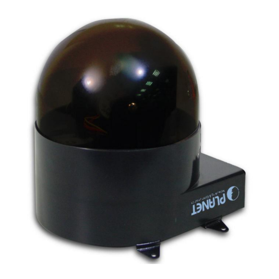
Page 1: Internet Camera
Internet Camera ICA-500 User’s Manual... -
Page 2: Declaration Of Conformity
Information in this User’s Manual is subject to change without notice and does not represent a commitment on the part of PLANET. PLANET assumes no responsibility for any inaccuracies that may be contained in this User’s Manual. PLANET makes no commitment to update or keep current the information in this User’s Manual, and reserves the right to make improvements to this User’s Manual and/or to the products... -
Page 3: Table Of Contents
Controlling User Access to the Video Stream ............... 12 Making Video available from the Internet..............13 CHAPTER 4 WEB-BASED MANAGEMENT ..............17 Introduction ........................17 Connecting to ICA-500....................17 Welcome Screen....................... 18 Viewing Area ........................19 Control Panel Screen....................... 20 Advanced Configuration Area .................. - Page 4 APPENDIX D SPECIFICATIONS..................69 Appendix D: Specifications..................... 69...
-
Page 5: Chapter 1 Introduction
ICA-500. The high quality of M-JPEG files brings vivid images, which are suitable for surveillance applications. Motion detection is a powerful function enhanced in ICA-500. If a motion is detected in surveillance spot, this function will capture images, attach them in an email, and alert the system administrator via pop-up message. -
Page 6: Internet Features
With built-in microphone, the voice around can be recorded with live image. Internet Features • User-definable administration port number This allows Internet Gateways to use “port mapping” so the ICA-500 a and a Web Server can share the same Internet IP address. • DDNS Support In order to view video over Internet, user must know the Internet IP address of the gateway used by ICA-500. -
Page 7: Physical Details
Physical Details ICA-500 Rear Panel Rear Panel LAN port Use a standard LAN cable to connect your ICA-500 to a 10/100BaseT hub or switch. Alarm I/O ICA-500 provides a terminal block with 8 pins of connectors Connector located on the center of the back panel. There are 3 pins for two alarm inputs and 5 pins are for alarm output. -
Page 8: Package Contents
Package Contents The following items should be included: If any of these items are damaged or missing, please contact your dealer immediately. • Planet ICA-500 Pan / Tilt Camera x 1 • Power adapter x 1 • Power cord x 1 •... -
Page 9: Chapter 2 Basic Setup
Chapter 2 Basic Setup This Chapter provides details of installing and configuring the ICA-500. System Requirements • To use the LAN interface, a standard 10/100BaseT hub or switch and network cable is required. • System Requirement for Viewer & Recorder:... -
Page 10: Installation
Installation 1. Mount the Camera on the supplied Base and Stand. Use 4 screws to fix the ICA-500 onto the ceiling as below. You can also put the Network Camera on the table directly. ICA-500 Installation 2. Connect the LAN Cable Connect the ICA-500 to a 10/100BaseT hub or switch. -
Page 11: Setup
Note Navigator support is planned in the future firmware release Default LAN interface IP address of ICA-500 is 192.168.0.20. You may now open your web browser, and insert http://192.168.0.20 in the address bar of your web browser to logon ICA-500 web configuration page. - Page 12 • Choose the destination camera for IP address and device name modifications • After modifications, you may now connect the camera via web browser.
-
Page 13: Chapter 3 Advanced Viewing Setup
ICA-500. This Chapter is for Administrators only. Introduction After finishing the network setup, the ICA-500 can immediately be used by all users on your LAN. This chapter describes some additional settings and options for viewing live Video: •... - Page 14 Camera setting 3. Make the required adjustments, as explained below, and save your changes. Camera Settings Image Size Select the desired video resolution. The default resolution is set to 320*240. Available resolution: ‧176x144‧320x240‧352x288 ‧ 640x480 Image Quality Select the desired image quality. The default Image Quality is set to Standard.
- Page 15 Please check the appendix B for more information on the image Note adjustment.
-
Page 16: Controlling User Access To The Video Stream
Controlling User Access to the Video Stream By default, only system administrators can connect to the ICA-500 and view live Video. If desired, you may apply the access privileges to known users, by requiring each user to login to the ICA-500 with their individual username and password. -
Page 17: Making Video Available From The Internet
500. This port is called the "HTTP Port2". (The first port is port 80.) The HTTP port2 is disabled in default settings. If you prefer to use a different port number than port 80, you can specify the port number on the ICA-500's Network screen, as shown below. - Page 18 This feature is normally called Port Forwarding or Virtual Servers in the router. The Port Forwarding/Virtual Server entry tells the Router/Gateway that incoming TCP connections should be passed to the ICA-500. If necessary, check the user manual for your Router/Gateway for further details.
-
Page 19: Viewing Via The Internet
Where the Router/Gateway's Domain name is ica500.dyndns.org and the " HTTP Port2" number on the ICA-500 is 1024. Using the Windows Viewing/Recording Utility If using the CamView Utility, the details of the ICA-500 must be entered on the Internet tab of the Add Camera screen. CamView - Add Camera Screen... - Page 20 You can then select the camera in the Cameras list on the main screen, and click OK to establish a connection and view live video. Please check respective chapter for further details of viewing Video using either the Windows Viewing/Recording utility or Web Browser.
-
Page 21: Chapter 4 Web-Based Management
Bookmarks. Connecting using your Web Browser 1. Start your web browser. 2. In the Address box, enter "HTTP://" and the IP Address of the ICA-500, as in this example, which uses the ICA-500's default IP Address: HTTP://192.168.0.20 3. Default username/password for machine login: admin/ <no password>... -
Page 22: Welcome Screen
The Home screen can be divided into three areas: • Viewing Area - Images from the ICA-500 • Control Panel Area – ICA-500 Camera Manipulation and image quality control • Advanced Configuration area - only available for administrator. Camera administrator can have full configuration in this menu. -
Page 23: Viewing Area
This screen is displayed when you log in machine Viewing Area Screen • The ICA-500 web page requires ActiveX control to display the video content. The ActiveX control must be downloaded from the camera and installed on your PC. •... -
Page 24: Control Panel Screen
Recall/Preset Preset: set up camera fixed locations before operation mode Recall: Set camera position to preset location Adjust Video resolution The ICA-500 provides 4 resolutions: 640x480, 352x288, 320x240, 176x144 Video For NTSC camera: 320x240 is suitable Resolution For PAL camera: 352x288 and 176x144 are suitable... -
Page 25: Advanced Configuration Area
Respective menu descriptions are illustrated in the following sections. Camera Advanced setting Menu Clicking on Setting on the menu provides privileges to all the settings for the ICA-500. The Advanced Setting menu is divided into 2 categories: Basic and Application... -
Page 26: System Screen
This displays the name for the ICA-500; camera name is useful while multiple unit installation. Default frame The default frame rate in ICA-500 is 30fps, the video frame rate rate can be adjusted in this menu or on the Control panel menu... -
Page 27: Camera Screen
Note: please adjust carefully to have proper machine configurations. Camera Screen Data - Camera Screen Camera Settings Image Size Display resolution selection, supported resolution in ICA-500: ‧176x144 ‧ 352x288 ‧ 320x240 ‧ 640x480 Please check the available network upload bandwidth and carefully select the proper video resolution. - Page 28 Saturation, Key in respective value for image adjustment. It is not required Sharpness, to adjust this value when the image is vivid. Contrast, Hue Camera Tour To use the camera tour function, user must preset some camera positions first. Select the “SET Tour” button to enter the Camera Tour setting page.
-
Page 29: Network Screen
Network screen Data - Network Screen Network Settings DHCP Enable or disable DHCP client in ICA-500 IP address, This parameter allows users to setup the IP address assigned by Subnet mask, ISP. Your ISP should provide all the information requied for Default Internet access. -
Page 30: Pppoe Setting
DDNS screen DDNS Settings Enable DDNS Enable or disable DDNS function. Username, Enter the Username/Password for your DDNS account. Password Domain Name Enter the host name, which DDNS service provider assigned. HTTP Proxy, Enter the parameter, which DDNS service provider assigned. Proxy Username, Proxy... - Page 31 PPPoE screen Please consult your ISP personnel to obtain proper PPPoE/IP Hint address related information, and input carefully. If Internet connection cannot be established, please check the physical connection or contact the ISP service staff for support information.
-
Page 32: User Screen
User Screen This User setting can set up to 10 different usernames and passwords. Every one set of username and password can be acted as an Administrator or just a general user. User Screen IP Filter Screen The IP filter can set 10 different user’s IP address, which are allowing enter or disregarding by the Network Camera. -
Page 33: Application Setting
Application Setting Parameters in the Basic configuration menu provide machine adjustment; the available configurations are listed below: Icon Menu Link Definition Setup IVS-100 as a FTP client and configure FTP Client Server site in order to upload images to server SMTP Setup Mail transferring service configuration Image... -
Page 34: Ftp Client Screen
FTP Client Screen FTP Client Screen FTP Client Settings FTP server IP address or domain name of the destination FTP server name Username, Please input the Username/Password for the FTP server Password Remote path Please input the path to the destination. Image file Please input the basic file name you want to assign to the images when sending to the FTP server. -
Page 35: Smtp Screen
SMTP Screen This screen is displayed when the SMTP menu option is clicked. SMTP (Simple Mail Transfer Protocol) is a protocol for sending e-mail messages between servers. The mail server address must be filled in this field. SMTP Screen Network Settings SMTP server Enter the address of SMTP server used to send the mail. - Page 36 Image Memory Setup CF memory card setting or view the pictures stored in CF memory card. User can store the pictures into CF memory card by enabling this function. It is useful to keep image as evidence even though without remote surveillance and remote recording.
- Page 37 We strongly suggest using SanDisk CF memory card to avoid compatible issue with this device. Note Because this device does not support plug and play function yet. Therefore, while you want to plug a CF memory card into slot, please make sure power off the device first, then plug this CF memory card carefully.
-
Page 38: Alarm 1 & Alarm 2 Screen
Alarm 1 & Alarm 2 Screen This screen is displayed when the Alarm 1/Alarm 2 menu option is clicked. You can select Manual or Event for the Alarm mode. Alarm1 Screen Schedule Screen The Schedule can enable motion detection in an arranged period in order to avoid unnecessary images transmitting and catch the desired images. -
Page 39: Motion Detection Screen
Enable/Disable function and adjust the sensitivity level Motion Detection Screen Motion Detection Settings Enable Motion Enable or disable Motion Detection function in ICA-500 Detection Sensitivity Select the desired option to suit your environment. If covering a large area, you usually need higher sensitivity, since a moving object will take only a small portion of the image. -
Page 40: Time Setting Screen
Time Setting Screen This screen is displayed when the Time Setting menu option is clicked. Time Screen Time Settings Provides settings of adjusting the camera’s time IP Cam Time PC Time This is default time value for PC. Set Time Three options of Synchronize with PC's time / User Input / NTP are available for your selection to link with the Time Server. -
Page 41: Popup Screen
Popup Screen This screen is displayed setting event message while motion or sensors has been activated When any one of alarms enabled, and one of them detected, then a message window will be displayed on the screen. Pop up Screen Pop up Settings Pop-up text Input the warming text. -
Page 42: Firmware Upgrade Screen
2. Select this file, and click OK. The filename will then appear in the Upgrade File field. Click the Start Upgrade button to transfer the file to the ICA-500 and start the upgrade procedure. Click the “here” button to begin to upgrade firmware. -
Page 43: Factory Default Screen
6. The upgrade progress status information will be displayed on the screen. Once the upgrading process completed, the Network Camera will reboot the system automatically. Do not interrupt the upgrading procedure during proceeding; or Hint the inner component might be permanently damaged. Factory Default Screen This screen is displayed when you click the Factory Default menu on the Status screen. -
Page 44: Activex Control
Trigger Settings Upload a captured image to server Mail captured image to specific mail address Mail Save images in attached CF memory card Image Memory Enable Alarm output 1 Alarm 1 Enable Alarm output 2 Alarm 2 Clear alarm1 output status Clear Alarm 1 Clear alarm2 output status Clear Alarm 2... - Page 45 View This screen is displayed when you click the “View” menu on the ActiveX control. View Settings Make the image is resizable, but “Actual size disable”, the Resizable “Splits” is supported on this mode. Make the image show as the actual size, the “Splits” function Actual size does not work on this mode.
-
Page 46: Image Recording
Split This screen is displayed when you click the “Split” menu on the ActiveX control. The Network Camera provides four setting for Window split, it can display different time frame images of the selected Network Camera. The time string with green characters is the current displayed image. - Page 47 Recoding Screen Save as JPEG: Select this option and click “Save as JPEG” for detailed configurations. The pre- defined schedule can be set by JPEG. During the JPGEG file recording, a red icon displays on lower right position of the image to indicate the AVI saving process.
-
Page 48: Save Current Picture As
Save as AVI: Select this option and click “Save as AVI” for detailed configurations. The pre-defined schedule can be set by AVI. During the AVI file recording, a red icon displays on lower right position of the image to indicate the AVI saving process. If want stop the recording, please press the “Stop Image Recording”... -
Page 50: Chapter 5 Client Utility
Chapter 5 Client UTILITY INSTALLATION The CamView utility for ICA-500 is a powerful utility for video recording, viewing, and camera administrations. Please insert the user’s manual CD and start the CamView installation from the default page or manually browse the Utility folder in the CD to install the software: 5.1. - Page 51 • Decide which directory to install the software. By default, just hit the Next button to continue...
- Page 52 • Decide the program group name. By default, just hit the Next button to continue. • Decide whether to create a desktop icon of the program. By default, just hit the Next button to continue.
- Page 53 • Ready to install. By default, just hit the Install button to start installation.
- Page 54 • Installing, wait for a moment. • Installation complete. Press Finish to launch the program. Otherwise, uncheck the check box to run the program later.
-
Page 55: How To Use
HOW TO USE After successfully installing the utility, this icon, , will be added to the desktop. Double click on it to launch the program. - Page 56 5.2. CamView User Interface 5.2. 5.2. 5.2. 5.2. 5.2. 5.2. 5.2. 5.2. CamView main screen. 5.2. 5.2.1. Date and Time The current date and time of the computer are displayed here. 5.2.2. Viewer Screen CamView is able to monitor up to 16 Internet cameras. Users may choose different layout to monitor different sites.
- Page 57 5.2.6. Camera Zoom Here are two buttons to zoom in or zoom out on the image. Note: camera zoom feature is reserved for future PTZ model. 5.2.7. Camera Pan/Tilt Control Here are five buttons to move the camera to the up, down, left, right and home, respectively 5.2.8.
- Page 58 Figure 5.3.1. The Application Tab 5.3.2. Camera Settings As shown in Figure 5.3.2, users can set parameters of each camera. If the Restore button is pressed, the current setting modifications of the specified camera will be cleared and restore to the original. If the Apply button is pressed, the current setting modifications will be applied to the specified camera.
- Page 59 Figure 5.3.2. The Camera Tab 5.3.3. Scheduling As shown in Figure 5.3.3, users can schedule recording tasks. When you press the Add button, the editing task will be added to the schedule item list. When the Modify button is pressed, the specified task will be updated. If the Remove button is pressed, the specified task will be removed from the list.
- Page 60 Figure 5.3.3. The Scheduling Tab 5.3.4. Application Settings Figure 5.3.4 shows settings for the global scope of the application including initialization and environment. After all settings are complete, press the OK button to save the configuration, and exit the form. The Apply button is unused for this tab.
- Page 61 Figure 5.3.4. The Application Tab 5.4. Camera Configuration Users can hit the button shown in Figure 5.4 to configure the specified camera. The configuration guide is not included in the document. Please read the documentation of the camera. Figure 5.4. 5.5.
- Page 62 Figure 5.5- Figure 5.5- Figure 5.5- Figure 5.5- 5.6. Playback When you press the Playback button on the panel as shown in Figure 5.6, a form will appear to show the list of video records and snapshots. Figure 5.6. 5.6.1. Video List The video list tab lists video records, and displays the information about the specified record.
- Page 63 Figure 5.6.2. The Snapshot List Tab 5.6.3. Video Search The video search tab lists video file information about the specified search. When you enter the search qualification, then hit the Search button, you will get the matched video files. Select an item, hit the Play button, Windows Media Player will be opened to play the video.
- Page 64 5.7. Image Rotation After the button is pressed, the display image rotates 180 degree. It is used for the camera being installed upside-down direction. Note video/images in recorded video will not be rotated. Figure 5.7. 5.8. eMap When you press the eMap button on the panel as shown in Figure 5.8, a form will appear to show the eMap function.
- Page 65 Figure 5.8.1. Layout example 1 Figure 5.8.2. Layout example 2...
- Page 66 • When your mouse moves over the camera icon, you can click the right button to display a menu which has options to set the configuration, show the record list, record, show video and remove the camera icon. Figure 5.8.3.
-
Page 67: Appendix A Troubleshooting
FTP locations, etc. ICA-500 provides a general I/O terminal block with two digital inputs and two outputs for device control. Pin 1 and 2 can be connected to an external sensor 1. Pin 2 and 3 can be connected to an external sensor 2. -
Page 68: Appendix B Troubleshooting
Appendix B Troubleshooting Appendix B Troubleshooting Q: The video and audio codec is adopted in the Network Camera? A: The Network Camera utilizes JPEG compression to providing high quality images. JPEG is a standard for image compression and can be applied to various web browsers without the need to install extra software. - Page 69 ICA-500 via a crossover cable. • Make sure the Internet connection and setting is ok. • Make sure enter the IP address of Internet Explorer is correct. If ICA-500 has a dynamic address, it may have changed since you last checked it.
- Page 70 • If the problem is not solved, the ICA-500 might be faulty. Contact your dealer for further help. Q: Image or video does not appear in the main page A: ‧ The first time the PC connects to ICA-500, a pop-up Security Warning window will appear to download ActiveX Controls.
- Page 71 .• If the object is dark, the image will flicker. Make the condition around the ICA- 500 brighter. Q: Noisy images occurs A: The video images might be noisy if the ICA-500 is located in a very low light environment. Make the condition around the ICA-500 brighter. Q: How to Reboot the ICA-500 A: If you just want to reboot system without change anything.
-
Page 72: Appendix C Bandwidth Calculation
Bandwidth Calculation Appendix C: Bandwidth Calculation The frame rate of video transmitted from the ICA-500 depends on connection bandwidth between client and server and quality setting of server. Here is a guideline to help you roughly estimate the bandwidth requirements form your ICA-500. -
Page 73: Specifications
Appendix D Specifications Appendix D: Specifications Model ICA-500 Hardware Sensor 1/3” CCD sensor Iris control Video-drive iris control Gain control High/Low switchable White balance Indoor, auto mode (color temperature: 2500K~9000K) Focus Fixed, lens length=3.6mm, manually fine tune Minimum Illumination 0.2LUX@F2.0 0°~325°...
Need help?
Do you have a question about the ICA-500 and is the answer not in the manual?
Questions and answers