Table of Contents
Advertisement
Quick Links
QQ
3 7 63 1515 0
Service
Manual
MULTI-CD CONTROL HIGH POWER CD PLAYER WITH FM/AM TUNER
DEH-P6200
- This service manual should be used together with the following manual(s):
Model No.
CX-958
TE
L 13942296513
CONTENTS
1. SAFETY INFORMATION ............................................2
2. EXPLODED VIEWS AND PARTS LIST .......................3
4. PCB CONNECTION DIAGRAM ................................26
5. ELECTRICAL PARTS LIST ........................................36
6. ADJUSTMENT..........................................................42
www
.
PIONEER CORPORATION
PIONEER ELECTRONICS SERVICE INC.
PIONEER EUROPE N.V.
PIONEER ELECTRONICS ASIACENTRE PTE.LTD. 253 Alexandra Road, #04-01, Singapore 159936
C PIONEER CORPORATION 2000
http://www.xiaoyu163.com
Order No.
Mech. Module
CRT2423
S8.1
x
ao
y
i
4-1, Meguro 1-Chome, Meguro-ku, Tokyo 153-8654, Japan
P.O.Box 1760, Long Beach, CA 90801-1760 U.S.A.
Haven 1087 Keetberglaan 1, 9120 Melsele, Belgium
http://www.xiaoyu163.com
8
Remarks
CD Mech. Module:Circuit Description, Mech.Description, Disassembly
Q Q
3
6 7
1 3
7. GENERAL INFORMATION .......................................46
7.1 DIAGNOSIS ........................................................46
7.1.1 TEST MODE ..............................................46
7.1.2 DISASSEMBLY .........................................50
7.2 PARTS .................................................................54
7.2.1 IC................................................................54
7.2.2 DISPLAY ....................................................60
7.3 OPERATIONAL FLOW CHART ...........................61
u163
8. OPERATIONS AND SPECIFICATIONS.....................62
.
2 9
9 4
2 8
X1N/UC
1 5
0 5
8
2 9
9 4
m
co
K-ZZU. FEB. 2000 Printed in Japan
9 9
ORDER NO.
CRT2468
2 8
9 9
Advertisement
Table of Contents

Related Manuals for Pioneer DEH-P6200


Summary of Contents for Pioneer DEH-P6200
-
Page 1: Table Of Contents
PIONEER ELECTRONICS SERVICE INC. P.O.Box 1760, Long Beach, CA 90801-1760 U.S.A. PIONEER EUROPE N.V. Haven 1087 Keetberglaan 1, 9120 Melsele, Belgium PIONEER ELECTRONICS ASIACENTRE PTE.LTD. 253 Alexandra Road, #04-01, Singapore 159936 C PIONEER CORPORATION 2000 K-ZZU. FEB. 2000 Printed in Japan http://www.xiaoyu163.com... -
Page 2: Safety Information
DEH-P6200 3 7 63 1515 0 - CD Player Service Precautions 2. During disassembly, be sure to turn the power off 1. For pickup unit(CXX1285) handling, please refer since an internal IC might be destroyed when a con- to"Disassembly"(see page 50). -
Page 3: Exploded Views And Parts List
DEH-P6200 3 7 63 1515 0 2. EXPLODED VIEWS AND PARTS LIST 2.1 PACKING L 13942296513 NOTE: - Parts marked by “*” are generally unavailable because they are not in our Master Spare Parts List. ∇ mark on the product are used for disassembly. -
Page 4: Manual
DEH-P6200 3 7 63 1515 0 2.2 EXTERIOR L 13942296513 u163 http://www.xiaoyu163.com... -
Page 5: Manual
DEH-P6200 3 7 63 1515 0 - EXTERIOR SECTION PARTS LIST Mark No. Description Part No. Mark No. Description Part No. 1 Screw ISS26P055FUC 51 Cushion CNM5486 2 Screw BMZ30P040FZK 52 Cover CNM6854 3 Screw BSZ26P060FMC 53 Panel CNS5791... -
Page 6: Manual
DEH-P6200 3 7 63 1515 0 2.3 CD MECHANISM MODULE L 13942296513 u163 http://www.xiaoyu163.com... -
Page 7: Manual
DEH-P6200 3 7 63 1515 0 - CD MECHANISM MODULE SECTION PARTS LIST Mark No. Description Part No. Mark No. Description Part No. 1 Control Unit CWX2411 46 ••••• 2 Connector(CN802) CKS2192 47 Ball CNR1189 3 Connector(CN801) CKS2193 48 Belt... -
Page 8: Block Diagram And Schematic Diagram
DEH-P6200 3 7 63 1515 0 3. BLOCK DIAGRAM AND SCHEMATIC DIAGRAM 3.1 BLOCK DIAGRAM TUNER AMP UNIT FM/AM TUNER UNIT FM MPX FM FRONT END FM/AM 1ST IF 10.7MHz CN502 Q51 CF51 CF52 CF53 DI/DO IC 2 PM4008A... -
Page 9: Manual
DEH-P6200 3 7 63 1515 0 RESET IC 631 S-80734ANDYI Q952 Q959 CN952 BACK UP BACK UP Q601 DALMON adpw ALARM ALARM IC 851 (VDD) ALARM TPD1018F SYSTEM -COM Q953 DRELAY bsens IC 601(1/2) PE5106B asens Q958 isens SDBW... -
Page 10: Manual
DEH-P6200 3.2 OVERALL CONNECTION DIAGRAM(GUIDE PAGE) 3 7 63 1515 0 Note: When ordering service parts, be sure to refer to “EXPLODED VIEWS AND PARTS LIST” or “ELECTRICAL PARTS LIST”. TUNER AMP UNIT Large size SCH diagram Guide page... -
Page 11: Manual
DEH-P6200 3 7 63 1515 0 L 13942296513 S-CD:36.5dBs CEK1136 u163 http://www.xiaoyu163.com... -
Page 12: Manual
DEH-P6200 3 7 63 1515 0 L 13942296513 u163 http://www.xiaoyu163.com... -
Page 13: Manual
DEH-P6200 3 7 63 1515 0 L 13942296513 u163 http://www.xiaoyu163.com... -
Page 14: Manual
DEH-P6200 3 7 63 1515 0 L 13942296513 u163 http://www.xiaoyu163.com... -
Page 15: Manual
DEH-P6200 3 7 63 1515 0 L 13942296513 u163 http://www.xiaoyu163.com... -
Page 16: Manual
DEH-P6200 3 7 63 1515 0 3.3 FM/AM TUNER UNIT FM/AM TUNER UNIT Mark Band Input Level None – – 0dBf 65dBf F125 125dBf 0dBµ 74dBµ A125 125dBµ L 13942296513 u163 http://www.xiaoyu163.com... -
Page 17: Manual
DEH-P6200 3 7 63 1515 0 L 13942296513 u163 http://www.xiaoyu163.com... -
Page 18: Manual
DEH-P6200 3 7 63 1515 0 3.4 KEYBOARD UNIT KEYBOARD UNIT L 13942296513 u163 http://www.xiaoyu163.com... -
Page 19: Manual
DEH-P6200 3 7 63 1515 0 L 13942296513 u163 http://www.xiaoyu163.com... -
Page 20: Manual
DEH-P6200 3 7 63 1515 0 3.5 CD MECHANISM MODULE CONTROL UNIT PICKUP UNIT (SERVICE)(P8) CN101 RF-AMP, SE L 13942296513 PHOTO UNIT(S8) CN802 Q1 CPT230SX-TU Q2 CPT230SX-TU SPINDLE MOTOR M3 CXB2562 CARRIAGE MOTOR M1 CXB2190 u163 LOADING MOTOR CD DRIVER... -
Page 21: Manual
DEH-P6200 3 7 63 1515 0 SWITCHES: CONTROL UNIT S801 : HOME SWITCH..ON-OFF S802 : CLAMP SWITCH..ON-OFF The underlined indicates the switch position. MP, SERVO, DSP, DAC, LPF L 13942296513 CN701 u163 http://www.xiaoyu163.com... -
Page 22: Manual
DEH-P6200 3 7 63 1515 0 Note:1. The encircled numbers denote measuring pointes in the circuit diagram. 2. Reference voltage REFO:2.5V - Waveforms 1 RFI 1 CH1: RFI 1 CH1: RFI 0.5V/div. 0.5µs/div. 1V/div. 1V/div. 0.5ms/div. 0.5ms/div. 2 CH2: MIRR... -
Page 23: Manual
DEH-P6200 3 7 63 1515 0 8 CH1: TE 8 CH1: TE 0 MD 0.2V/div. 0.5V/div. 0.5V/div. 0.1s/div. 20ms/div. 5ms/div. 9 CH2: TD ! CH2: SD 0.2V/div. 0.5V/div. Normal mode: play TEST mode: 100 Tracks jump(FWD) Normal mode: Play (12cm) →... -
Page 24: Manual
DEH-P6200 3 7 63 1515 0 ( CH1: R OUT 6 CH1: FE 8 CH1: TE 1V/div. 0.2V/div. 0.2V/div. 0.2ms/div. 1ms/div. 1ms/div. ) CH2: L OUT 3 CH2: FD 9 CH2: TD 1V/div. 0.5V/div. 0.5V/div. Normal mode: Play (1kHz 0dB) -
Page 25: Manual
DEH-P6200 3 7 63 1515 0 3.6 PANEL PCB UNIT PANEL PCB UNIT IL GND ILGND IL+B IL +B CSENS BL+B SW5V FLAP IL+ uGND FLAP IL- DPDT CSENS EJECT KYDT EJECT ROT0(L) uGND ROT1(H) SW5V DPDT L 13942296513... -
Page 26: Pcb Connection Diagram
DEH-P6200 3 7 63 1515 0 4. PCB CONNECTION DIAGRAM 4.1 TUNER AMP UNIT CORD ASSY NOTE FOR PCB DIAGRAMS TUNER AMP UNIT 1. The parts mounted on this PCB include all necessary parts for several destination. For further information for... -
Page 27: Manual
DEH-P6200 3 7 63 1515 0 CORD ASSY SIDE A L 13942296513 u163 CN902 http://www.xiaoyu163.com... -
Page 28: Manual
DEH-P6200 3 7 63 1515 0 TUNER AMP UNIT L 13942296513 u163 http://www.xiaoyu163.com... -
Page 29: Manual
DEH-P6200 3 7 63 1515 0 SIDE B L 13942296513 u163 http://www.xiaoyu163.com... -
Page 30: Manual
DEH-P6200 3 7 63 1515 0 4.2 FM/AM TUNER UNIT SIDE A L 13942296513 u163 http://www.xiaoyu163.com... -
Page 31: Manual
DEH-P6200 3 7 63 1515 0 SIDE B L 13942296513 u163 http://www.xiaoyu163.com... -
Page 32: Manual
DEH-P6200 4.3 KEYBOARD UNIT 3 7 63 1515 0 SIDE A SIDE B L 13942296513 u163 http://www.xiaoyu163.com... -
Page 33: Manual
DEH-P6200 3 7 63 1515 0 4.4 PANEL PCB UNIT PANEL PCB UNIT SIDE A EJECT CN901 L 13942296513 SIDE B PANEL PCB UNIT CN651 u163 http://www.xiaoyu163.com... -
Page 34: Manual
DEH-P6200 3 7 63 1515 0 4.5 CD MECHANISM MODULE SIDE A L 13942296513 u163 http://www.xiaoyu163.com... -
Page 35: Manual
DEH-P6200 3 7 63 1515 0 SIDE B L 13942296513 u163 http://www.xiaoyu163.com... -
Page 36: Electrical Parts List
DEH-P6200 3 7 63 1515 0 5. ELECTRICAL PARTS LIST NOTES: - Parts whose parts numbers are omitted are subject to being not supplied. - The part numbers shown below indicate chip components. Chip Resistor RS1/_S___J,RS1/__S___J Chip Capacitor (except for CQS..) CKS.., CCS.., CSZS.. -
Page 37: Manual
DEH-P6200 3 7 63 1515 0 =====Circuit Symbol and No.===Part Name Part No. =====Circuit Symbol and No.===Part Name Part No. ------ ------------------------------------------ ------------------------- ------ ------------------------------------------ ------------------------- RS1/10S223J RS1/10S222J RS1/10S223J RS1/10S222J RS1/10S223J RS1/10S473J RS1/10S223J RS1/10S473J RS1/10S102J RS1/10S473J RS1/16S0R0J RS1/10S473J RS1/16S0R0J... -
Page 38: Manual
DEH-P6200 3 7 63 1515 0 =====Circuit Symbol and No.===Part Name Part No. =====Circuit Symbol and No.===Part Name Part No. ------ ------------------------------------------ ------------------------- ------ ------------------------------------------ ------------------------- RS1/10S473J CKSQYB183K50 RS1/16S473J CKSQYB183K50 RS1/10S103J CKSQYB472K50 RS1/10S473J CCSQCH101J50 RS1/10S472J CCSQCH101J50 RS1/10S103J CKSYB474K16 RS1/10S473J... -
Page 39: Manual
DEH-P6200 3 7 63 1515 0 =====Circuit Symbol and No.===Part Name Part No. =====Circuit Symbol and No.===Part Name Part No. ------ ------------------------------------------ ------------------------- ------ ------------------------------------------ ------------------------- NSSW440-9159 CKSQYB103K50 NSSW440-9159 CKSQYB104K50 Inductor LCTA101J3225 CKSQYB104K50 Radiator 5.00MHz CSS1423 CKSQYB104K50 Push Switch... - Page 40 DEH-P6200 3 7 63 1515 0 =====Circuit Symbol and No.===Part Name Part No. =====Circuit Symbol and No.===Part Name Part No. ------ ------------------------------------------ ------------------------- ------ ------------------------------------------ ------------------------- CEV101M6R3 RESISTORS CKSRYB104K16 CKSRYB104K16 CKSRYB104K16 RS1/16S183J CKSRYB104K16 RS1/16S103J RS1/16S0R0J CKSRYB332K50 RS1/16S273J CKSRYB104K16 RS1/16S473J...
-
Page 41: Manual
DEH-P6200 3 7 63 1515 0 =====Circuit Symbol and No.===Part Name Part No. =====Circuit Symbol and No.===Part Name Part No. ------ ------------------------------------------ ------------------------- ------ ------------------------------------------ ------------------------- CCSRCJ3R0C50 CKSRYB103K50 CKSRYB103K50 CCSRTH100D50 CKSRYB103K50 CCSRTH150J50 CKSRYB103K50 CCSRTH100D50 CKSQYB334K16 CKSRYB332K50 CKSRYB472K50 CKSQYB474K16 CCSRCH220J50... -
Page 42: Adjustment
DEH-P6200 3 7 63 1515 0 6. ADJUSTMENT 6.1 CD ADJUSTMENT 1) Precautions 2) Test Mode • This unit uses a single power supply (+5V) for the reg- This mode is used for adjusting the CD mechanism ulator. The signal reference potential, therefore, is module of the device. -
Page 43: Manual
DEH-P6200 3 7 63 1515 0 - Flow Chart Test Mode In Reset SOURCE Select CD New test mode BAND Power ON (Adjustment for T.Offset) Power ON RF AMP Gain Select (Not adjustment for T.Offset) 00 00 00 Display... -
Page 44: Manual
DEH-P6200 3 7 63 1515 0 6.2 CHECKING THE GRATING AFTER CHANGING THE PICKUP UNIT • Note : The grating angle of the PU unit cannot be adjusted after the PU unit is changed. The PU unit in the CD mecha- nism module is adjusted on the production line to match the CD mechanism module and is thus the best adjusted PU unit for the CD mechanism module. -
Page 45: Manual
DEH-P6200 3 7 63 1515 0 Ech → Xch 20mV/div, AC Grating waveform Fch → Ych 20mV/div, AC 0° 30° 45° 60° L 13942296513 75° 90° u163 http://www.xiaoyu163.com... -
Page 46: General Information
DEH-P6200 3 7 63 1515 0 7. GENERAL INFORMATION 7.1 DIAGNOSIS 7.1.1 TEST MODE - Error Messages If a CD is not operative or stopped during operation due to an error, the error mode is turned on and cause(s) of the error is indicated with a corresponding number. -
Page 47: Manual
DEH-P6200 3 7 63 1515 0 - New Test Mode S-CD plays the same way as before. If an error such as off focus, spindle unlocking, unreadable sub-code, or sound skipping occurs after setup, its cause and time occurred (in absolute time) are displayed. -
Page 48: Manual
DEH-P6200 3 7 63 1515 0 (4) Display of Operational Status (CPOINT) during Setup Status No. Contents Protective action CD+5V ON process in progress. None Servo LSI initialization (1/3) in progress. None Servo LSI CRAM initialization in progress. None Servo LSI initialization (2/3) in progress. -
Page 49: Manual
DEH-P6200 3 7 63 1515 0 (5) Display Examples 1) During Setup (When status no. = 11) TRK No. MIN. SEC. 11" 2) During Operation (TOC read, TRK search, Play, FF and REV) The same as in the normal mode. -
Page 50: Disassembly
DEH-P6200 3 7 63 1515 0 7.1.2 DISASSEMBLY Removing the Case Unit (not shown) Remove the case unit. CD Mechanism Module Removing the CD Mechanism Module (Fig.1) Remove the four screws. Disconnect the connector and then remove the CD Mechanism Module (not shown). -
Page 51: Manual
DEH-P6200 3 7 63 1515 0 - Removing the Upper Frame 1. Remove six Springs A, two Springs B and four Upper Frame Screws. 2. Remove two Tabs situated on rear side of the Upper Frame, remove two Arms on the front side, then remove two Tabs on the front side. -
Page 52: Manual
DEH-P6200 3 7 63 1515 0 - Removing the Guide Arm Assy 1. Remove a connector, a spring A and B Guide Arm Assy Section 2. Drive the Guide Arm Assy up aslant into rear side direction, then remove it from a Pin. Finally, drive the assembly approximately 45 degrees upward, then slide the assembly toward left side to remove it. -
Page 53: Manual
DEH-P6200 3 7 63 1515 0 - Removing the Loading Motor and Carriage Motor Guide 1. Remove the Spring and two Screws A. 2. Dismount the Loading Motor. 3. Remove the Belt, a Screw B, two Screws C, a Guide... -
Page 54: Parts
DEH-P6200 3 7 63 1515 0 7.2 PARTS 7.2.1 IC - Pin Functions (UPD63711GC) Pin No. Pin Name Function and Operation D.GND Logic circuit GND RFOK RFOK signal output Reset signal input Command/parameter identification signal input Data strobe signal input... -
Page 55: Manual
DEH-P6200 3 7 63 1515 0 Pin No. Pin Name Function and Operation TSTB CD-TEXT parameter strobe signal input D.GND Logic circuit GND TEST0 Test pin TEST1 Test pin ATEST Test pin A.GND Analog circuit GND Focus drive output... -
Page 56: Manual
DEH-P6200 3 7 63 1515 0 S-81250SGUP PML004AF L 13942296513 u163 http://www.xiaoyu163.com... -
Page 57: Manual
DEH-P6200 3 7 63 1515 0 - Pin Functions (PE5106B) Pin No. Pin Name Function and Operation swvdd Keyboard unit power supply control output dsens Grille detach sense input Not used TESTIN Test program mode input Not used TELIN... -
Page 58: Manual
DEH-P6200 3 7 63 1515 0 Pin No. Pin Name Function and Operation Clock adjustment output MIRR CD mirror detection input clamp CD disc clamp input xsck CD LSI clock output CD LSI data input CD LSI data output... -
Page 59: Manual
DEH-P6200 3 7 63 1515 0 - Pin Functions (PD6279A) Pin No. Pin Name Function and Operation 1–42 SEG41–0 LCD segment output 43–46 COM3–0 LCD common output 47–49 V1–V3 LCD bias power supply Power supply terminal LED control output... -
Page 60: Display
DEH-P6200 3 7 63 1515 0 7.2.2 DISPLAY - CAW1565 L 13942296513 u163 http://www.xiaoyu163.com... -
Page 61: Operational Flow Chart
DEH-P6200 3 7 63 1515 0 7.3 OPERATIONAL FLOW CHART Power ON VDD=5V 19pin bsens 93pin asens 92pin dsens 2pin L 13942296513 adpw←H 22pin Starts communication with Grille microcomputer. 300ms swvdd←L 1pin 300ms In case of the above signal, the communication Source keys with Grille microcomputer may fail. -
Page 62: Operations And Specifications
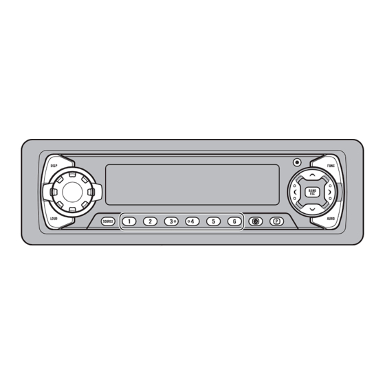
SOURCE/OFF button CLOCK button Remote Controller (for DEH-P6200) A remote controller that enables remote operation of the head unit is supplied only for DEH-P6200. Operation is the same as when using buttons on the head unit. +/– button Raise or lower the volume. -
Page 63: Manual
DEH-P6200 3 7 63 1515 0 L 13942296513 u163 http://www.xiaoyu163.com... -
Page 64: Manual
DEH-P6200 3 7 63 1515 0 L 13942296513 u163 http://www.xiaoyu163.com... -
Page 65: Manual
DEH-P6200 3 7 63 1515 0 L 13942296513 u163 http://www.xiaoyu163.com... -
Page 66: Manual
DEH-P6200 - CONNECTION DIAGRAM 3 7 63 1515 0 L 13942296513 u163 http://www.xiaoyu163.com... -
Page 67: Manual
DEH-P6200 3 7 63 1515 0 8.2 SPECIFICATIONS General CD player Power source ..14.4 V DC (10.8 – 15.1 V allowable) System ........Compact disc audio system Grounding system ........Negative type Usable discs ..........Compact disc Max. current consumption ........10.0 A Signal format ....
Need help?
Do you have a question about the DEH-P6200 and is the answer not in the manual?
Questions and answers