Table of Contents
Advertisement
Quick Links
LZ-701W
7-inch WIDE SCREEN MONITOR
INSTRUCTION MANUAL
MONITEUR GRAND ECRAN 7 pouces
MODE D'EMPLOI
7-Zoll BREITBILD MONITOR
BEDIENUNGSANLEITUNG
7 inch BREEDBEELDMONITOR
GEBRUIKSAANWIJZING
MONITOR A SCHERMO AMPIO 7 pollici
ISTRUZIONI PER L'USO
MONITOR DE PANTALLA PANORÁMICA DE 7 pulgadas
MANUAL DE INSTRUCCIONES
MONITOR DE ECRÃ LARGO de 7 polegadas
MANUAL DE INSTRUÇÕES
© PRINTED IN JAPAN B64-1932-00+ (E)
LA DICHIARAZIONE DI CONFORMITA' "CE"
DI QUESTO PRODOTTO E' DEPOSITATA
PRESSO:
KENWOOD ELECTRONICS EUROPE B.V.
AMSTERDAMSEWEG 37
1422 AC UITHOORN
THE NETHERLANDS
Advertisement
Table of Contents

Related Manuals for Kenwood LZ-701W


Summary of Contents for Kenwood LZ-701W
-
Page 1: Instruction Manual
MANUAL DE INSTRUCCIONES MONITOR DE ECRÃ LARGO de 7 polegadas MANUAL DE INSTRUÇÕES © PRINTED IN JAPAN B64-1932-00+ (E) LA DICHIARAZIONE DI CONFORMITA' "CE" DI QUESTO PRODOTTO E' DEPOSITATA PRESSO: KENWOOD ELECTRONICS EUROPE B.V. AMSTERDAMSEWEG 37 1422 AC UITHOORN THE NETHERLANDS... -
Page 2: Table Of Contents
Contents Safety Precautions........3 Operation Power .............4 Switching the Monitor’s Picture . -
Page 3: Safety Precautions
NOTE • If you experience problems during installation, consult your Kenwood dealer. • If the unit does not seem to be working right, try pressing the reset button first. If that does not solve the problem, consult your Kenwood dealer. -
Page 4: Operation
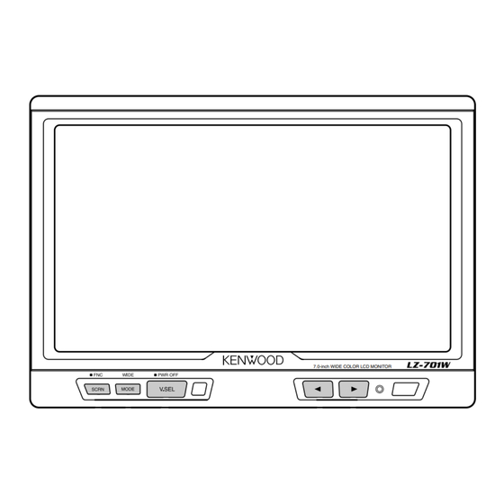
Operation V.SEL MODE SCRN Power Turning on the power Press the V.SEL button. Turning off the power Press the V.SEL button for at least two seconds. Switching the Monitor’s Picture <When the KTC-V800N or KTC-V800P is connected> Each time you press the V.SEL button, the monitor’s picture switches as follows: ∞... -
Page 5: Adjusting The Picture Quality
[ FULL ] [ NORMAL ] NOTE You cannot operate when the navigation picture is displayed. <When the KTC-V800N or KTC-V800P is connected> Adjusting the Picture Quality Press the SCRN button, the picture quality adjustment screen to be displayed. Each time you press the SCRN button, the adjustment item can be selected.. Press the [ 2 ] or [ 3 ] button to adjust the value. -
Page 6: Selecting The Channels
Operation V.SEL MODE SCRN Selecting the Channels <When the KTC-V800N or KTC-V800P is connected> Auto Seek Mode (AUTO1) Press the [ 3 ] button to seek for channels up the band. Press the [ 2 ] button to seek for channels down the band. Preset Station Seek Mode (AUTO2) Press the [ 3 ] button to move to the next preset station. -
Page 7: Selecting The Seek Mode
Selecting the Seek Mode [SEEK MODE] <When the KTC-V800N or KTC-V800P is connected> You can choose from three seek modes: auto seek, preset station seek, and manual seek. Press the [ 2 ] or [ 3 ] button, the mode switches as follows: [AUTO 1]: Auto Seek Mode ∞... -
Page 8: Setting The Remote Sensor On/Off
Setting the Remote Sensor On/Off [REMOTE] If this unit also runs when operating other units with different Kenwood remote controls, its remote control function can be turned off. Press the [ 2 ] or [ 3 ] button to switch the function on and off. -
Page 9: Remote Control Function
Remote Control Function <Provided with the KTC-V800N/KTC-V800P> 2CAUTION Do not set the remote on hot places such as above the dashboard. Loading and Replacing the Batteries 1. Use two "AA" batteries: Slide the cover while pressing downwards to remove it as illustrated. -
Page 10: Installation
Installation Accessories External view Installation Procedure 1. To prevent short circuits, remove the key from the ignition and disconnect the · terminal of the battery. 2. Make the proper input and output wire connections for each unit. 3. Connect the wiring harness wires in the following order: ground, ignition. 4. -
Page 11: Installation For Monitor Unit
• Be sure to use the supplied screws for installation. Using screws longer than those supplied may destroy parts inside the unit causing it to smoke. Using screws shorter than those supplied may cause the unit to come looks from the installation bracket. •... - Page 12 Installation Installation for Monitor Unit Installation location and cleaning Select for installation a location where the stand can be placed completely horizontal or where the front edge of the support (petal-shaped part) can be attached horizontally as shown in Figure A. Do not install in locations where the entire support is at a diagonal such as in Figure B or where the monitor unit is facing down such as in Figure C.
- Page 13 Accessory 3 Tighten Loosen Tighten Loosen Protective strip Accessory 4 (Ø4 x 12 mm) Installation surface...
-
Page 14: Installation For The Video Box Unit
Installation Installation for the Video Box Unit Accessory 5 (Ø4 x 16 mm) -
Page 15: Connection
Connection KTC-V800N/KTC-V800P OUTPUT INPUT INPUT Accessory 1 +12 V 2 CAUTION For the sake of safety, be sure to connect the parking sensor. Parking sensor wire (Green) Ignition key switch Ground wire (Black) · (To car chassis) – Battery Monitor Unit ANTENNA Accessory 2 PRK SW... -
Page 16: Troubleshooting Guide
Wait a while after turning power on for the temperature to rise. Normal brightness will return. • Separate the two antennas as far as possible. • Turn off the LZ-701W. -
Page 17: Specifications
Specifications Specifications subject to change without notice. Monitor Unit Screen size ...7.0 inches wide Display system ...Transparent TN LCD panel Drive system ...TFT active matrix system Number of pixels ...336,960 pixels (480 H x 234 V x RGB) Effective pixels ...99.99% Pixel arrangement ...RGB striped arrangement Back lighting ...Cold cathode tube Video Box Unit...
Need help?
Do you have a question about the LZ-701W and is the answer not in the manual?
Questions and answers