
Related Manuals for Microsens MS400830M


Summary of Contents for Microsens MS400830M
-
Page 1: User Manual
24 Port Gigabit Ethernet PoE Switch User Manual MS400830M Release 1.44 April, 2014... -
Page 2: Table Of Contents
3-4-3. Software Upgrade ........................65 3-4-4. Configuration File Transfer ....................66 3-4-5. Logout ............................67 4. MAINTENANCE ..................... 68 4-1. R ESOLVING ONDITION ......................68 4-2. Q&A ............................... 68 DISCLAIMER ....................69 ©2014 MICROSENS GmbH & Co. KG – Hamm/Germany www.microsens.com... - Page 3 24 Port Gigabit Ethernet PoE Switch – User Manual ________________________________________________________________________ APPENDIX A TECHNICAL SPECIFICATIONS ............. 70 ©2014 MICROSENS GmbH & Co. KG – Hamm/Germany www.microsens.com...
-
Page 4: Electronic Emission Notices
It is expressly prohibited to open the switch! Damage caused by opening will be charged. Do not place product at outdoor or sandstorm. Before installation, please make sure input power supply and product specifications are compatible to each other. ©2014 MICROSENS GmbH & Co. KG – Hamm/Germany www.microsens.com... -
Page 5: Introduction
IEEE802.3af standard. It provides the endpoint with 48VDC power through RJ-45 pin 1, 2, 3, 6. Totally 370 watts for PoE powering are provided (Up to 15.4 W for 24 ports). ©2014 MICROSENS GmbH & Co. KG – Hamm/Germany www.microsens.com... -
Page 6: Checklist
Supports Quality of Service (QoS) for real time applications based information taken from Layer 2 to Layer 3. Built-in web-based management instead of using CLI interface, providing a more convenient GUI for the user ©2014 MICROSENS GmbH & Co. KG – Hamm/Germany www.microsens.com... -
Page 7: View Of 24 Port Gigabit Ethernet Switch
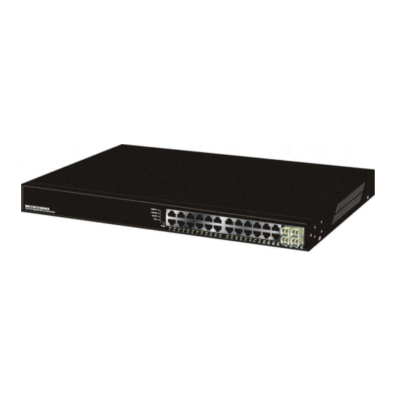
________________________________________________________________________ 1-4. View of 24 Port Gigabit Ethernet Switch Fig. 1-1 Full View of 24 Port Gigabit Ethernet Switch: MS400830M 1-4-1. User Interfaces on the Front Panel (Button, LEDs and Plugs) There are 20 TP Ports (10/100/1000Base-T) and 4 dual media ports (UTP/SFP) on the front side. -
Page 8: User Interfaces On The Rear Panel
Lit Yellow when SFP link on 100Mbps speed Off when no link occur Table1-1 1-4-2. User Interfaces on the Rear Panel Fig. 1-3 Rear view 1-5. View of Optional Modules Fig. 1-4 Front view of standard SFP transceiver ©2014 MICROSENS GmbH & Co. KG – Hamm/Germany www.microsens.com... -
Page 9: Installation
3. Install the media cable for network connection 4. Repeat the above steps, as needed, for each module to be installed into slot(s) 5. Have the power ON after the above procedures are done ©2014 MICROSENS GmbH & Co. KG – Hamm/Germany www.microsens.com... -
Page 10: Cabling Requirements
The grade of the cable must be Cat. 5 or Cat. 5e with a maximum length of 100 meters. Gigabit Ethernet TP network connection The grade of the cable must be Cat. 5 or Cat. 5e with a maximum length of 100 meters. Cat. 5e is recommended. ©2014 MICROSENS GmbH & Co. KG – Hamm/Germany www.microsens.com... - Page 11 For full-duplex operation, this will not be applied. You may use the TP-Fiber module to extend the TP node distance over fiber optic and provide the long haul connec- tion. ©2014 MICROSENS GmbH & Co. KG – Hamm/Germany www.microsens.com...
- Page 12 1. The same VLAN members could not be in different switches. 2. Every VLAN members could not access VLAN members each other. 3. The switch manager has to assign different names for each VLAN groups at one switch. ©2014 MICROSENS GmbH & Co. KG – Hamm/Germany www.microsens.com...
- Page 13 4. VLAN4 members could not access VLAN1 and VLAN3 members, but they could ac- cess VLAN2 members. Case3a: The same VLAN members can be at different switches with the same VID (See Fig. 2-5) Fig. 2-5 Attribute-based VLAN Diagram ©2014 MICROSENS GmbH & Co. KG – Hamm/Germany www.microsens.com...
-
Page 14: Configuring The Management Agent
Please refer to Fig. 2-6 about the default IP address in- formation. 2. Run web browser and follow the menu. Please refer to Chapter 3. Fig. 2-7 the Login Screen for Web ©2014 MICROSENS GmbH & Co. KG – Hamm/Germany www.microsens.com... -
Page 15: Ip Address Assignment
16-bit network prefix followed 16-bit host address. There are 16,384 (2^14)/16 networks able to be defined with a maximum of 65534 (2^16 –2) hosts per network. Bit # 01 2 15 16 Network address Host address ©2014 MICROSENS GmbH & Co. KG – Hamm/Germany www.microsens.com... - Page 16 B network, the third byte is used to identify the subnet within this class B network and, of course, the last byte is the host number. ©2014 MICROSENS GmbH & Co. KG – Hamm/Germany www.microsens.com...
- Page 17 In this case, subnet mask must be applied. For different network applications, the subnet mask may look like 255.255.255.240. ©2014 MICROSENS GmbH & Co. KG – Hamm/Germany www.microsens.com...
- Page 18 IP address such as 192.168.1.x must be set on your PC. Second, Subnet Mask: as shown in the Fig. 2-9, enter “255.255.255.0”. Any sub- net mask such as 255.255.255.x is allowable in this case. ©2014 MICROSENS GmbH & Co. KG – Hamm/Germany www.microsens.com...
-
Page 19: Typical Applications
Fig. 2-10 Network Connection between Remote Site and Central Side Fig. 2-10 is a system wide basic reference connection diagram. This diagram demonstrates how the switch connects with other network devices and hosts. ©2014 MICROSENS GmbH & Co. KG – Hamm/Germany www.microsens.com... -
Page 20: Fig. 2-12 Office Network Connection
24 Port Gigabit Ethernet PoE Switch – User Manual Page 16 of 72 ________________________________________________________________________ Fig. 2-11 Peer-to-peer Network Connection Fig. 2-12 Office Network Connection ©2014 MICROSENS GmbH & Co. KG – Hamm/Germany www.microsens.com... -
Page 21: Operation Of Web-Based Management
Web Smart Switch supports a simplified user management function which allows only one administrator to configure the switch at one time. To optimize the display effect, we recommend Microsoft IE and 1024x768 display resolution. Fig. 3-1 ©2014 MICROSENS GmbH & Co. KG – Hamm/Germany www.microsens.com... -
Page 22: Web Management Home Overview
“SNMP”, and “Maximum Packet Length”. With this information, you will know the software version, MAC address, ports available and so on. It would be helpful while malfunction occurred. For more details, please refer to Section 3-4-1. Fig. 3-2 ©2014 MICROSENS GmbH & Co. KG – Hamm/Germany www.microsens.com... -
Page 23: Page Layout
As to the function names in normal type are the sub-functions. When clicking it, the function is performed. The following list is the main function tree for web user interface. Root Configuration Monitoring Maintenance ©2014 MICROSENS GmbH & Co. KG – Hamm/Germany www.microsens.com... -
Page 24: Configuration
Configuration includes the following functions: System Information, Ports Configu- ration, VLAN Mode Configuration, VLAN Group Configuration, VLAN Isolation, PoE, Aggre- gation, RSTP, IGMP Snooping, Mirroring, QoS, Loop Detection, Broadcast Strom Protec- tion and SNMP. ©2014 MICROSENS GmbH & Co. KG – Hamm/Germany www.microsens.com... -
Page 25: System Information
IP address, active subnet mask, active gateway, DHCP server and Lease time left. Set device name, DHCP enable, fallback IP address, fallback subnet mask, fallback gateway, management VLAN, password and inactivity timeout. ©2014 MICROSENS GmbH & Co. KG – Hamm/Germany www.microsens.com... - Page 26 DHCP server is available via the network. Default: disabled Fallback IP Address: Users can configure the IP settings and fill in new values. Then, click <Apply> button to update. Default: 192.168.1.1 ©2014 MICROSENS GmbH & Co. KG – Hamm/Germany www.microsens.com...
- Page 27 Set the auto-logout timer. The valid value is 0 ~ 60 in the unit of minute and a decimal point is not allowed. The value 0 means auto-logout timer is disabled. Default: 0 ©2014 MICROSENS GmbH & Co. KG – Hamm/Germany www.microsens.com...
-
Page 28: Port Configuration
Port Configuration is applied for the settings of the ports on the switch. By this function, you can set or reset the values for mode and Flow Control. Fig. 3-4 Port Configuration ©2014 MICROSENS GmbH & Co. KG – Hamm/Germany www.microsens.com... - Page 29 When it is disabled, there will be no flow con- trol in the port. It drops the packet if too much to handle. Default: disabled ©2014 MICROSENS GmbH & Co. KG – Hamm/Germany www.microsens.com...
-
Page 30: Vlan Mode Configuration
The switch supports supplement of 802.1q. Each tag-based VLAN you built up must be assigned VLAN name and VLAN ID. Valid VLAN ID is 1-4094. User can create total up to 4094 Tag VLAN groups. ©2014 MICROSENS GmbH & Co. KG – Hamm/Germany www.microsens.com... -
Page 31: Vlan Group Configuration
Up to 16 VLANs are supported. This page allows for adding and de- leting VLANs as well as adding and deleting port members of each VLAN. Fig. 3-5-1 tag- VLAN Mode Fig. 3-5-2 Per port configuration ©2014 MICROSENS GmbH & Co. KG – Hamm/Germany www.microsens.com... - Page 32 VID of the outgoing packets with tag is the same as the one in the field of Untagged VID of this port. Untagged VID: Valid range is 1~4094. It works only when role is set to Hybrid. ©2014 MICROSENS GmbH & Co. KG – Hamm/Germany www.microsens.com...
- Page 33 You can easily create and delete a VLAN group by pressing <Add> and <Delete> function buttons, or clicking the Group ID directly to edit it. Fig. 3-6 Port-Based VLAN Configuration Fig. 3-7 Add or Remove VLAN Member ©2014 MICROSENS GmbH & Co. KG – Hamm/Germany www.microsens.com...
-
Page 34: Vlan Port Isolation Configuration
This page is used for enabling or disabling port isolation on ports in a Private VLAN. A port member of a VLAN can be isolated to other isolated ports on the same VLAN and Private VLAN. Port Isolation configuration Fig. 3-9 ©2014 MICROSENS GmbH & Co. KG – Hamm/Germany www.microsens.com... -
Page 35: Poe
Device) or not. The switch also manages the power supplement based on the class of the PD, and it will stop supplying the power once the power required by the PD excesses the class, short circuit or over temperature occurs. Fig. 3-10 ©2014 MICROSENS GmbH & Co. KG – Hamm/Germany www.microsens.com... - Page 36 It is a solution to avoid rush current to cause shorter PD. The available time period is from 0 to 300 seconds and 0 means disable the function Reset Port: To reset the port PoE configuration and status ©2014 MICROSENS GmbH & Co. KG – Hamm/Germany www.microsens.com...
-
Page 37: Aggregation
Set up the ports that do not join any aggregation trunking group. Group 1~8: Group the ports you choose together. Up to 2 to 12 ports can be selected for each group. ©2014 MICROSENS GmbH & Co. KG – Hamm/Germany www.microsens.com... -
Page 38: Rstp
Function name RSTP System Configuration Function description This screen is used to display the RSTP system configuration and set the need of parameters. RSTP Fig. 3-12 RSTP System Configuration ©2014 MICROSENS GmbH & Co. KG – Hamm/Germany www.microsens.com... - Page 39 Select RSTP or STP protocol from the drop-down list box. Function name RSTP Port Configuration Function description Enable or disable RSTP protocol on the ports that are selected and set path cost. ©2014 MICROSENS GmbH & Co. KG – Hamm/Germany www.microsens.com...
- Page 40 Path cost is the cost of transmitting a frame on to a LAN through that port. It is assigned according to the speed of the bridge. The slower the media, the higher the cost, user can select auto or set the rage from 1 to 200000000. ©2014 MICROSENS GmbH & Co. KG – Hamm/Germany www.microsens.com...
-
Page 41: Igmp Snooping
Unregistered IGMP Flooding enabled: ) Just tick the check box ( to enable this function. Default: enabled VLAN ID: At the IGMP Enable mode being selected, it will list the VLAN ID number. ©2014 MICROSENS GmbH & Co. KG – Hamm/Germany www.microsens.com... - Page 42 After IGMP Enabled function start up then user can tick the check box ( enable this function. Default: enabled IGMP Querying Enabled: ) After IGMP Enabled function start up then user can tick the check box ( enable this function. Default: enabled ©2014 MICROSENS GmbH & Co. KG – Hamm/Germany www.microsens.com...
-
Page 43: Mirroring Configuration
Set up the port for being monitored. Just tick the check box ( beside the port x and valid port is Port 1~24. Mirror Port: Use the drop-down menu to select a mirror port. ©2014 MICROSENS GmbH & Co. KG – Hamm/Germany www.microsens.com... -
Page 44: Qos (Quality Of Service) Configuration
3 is mapping to queue normal, priority 4 is mapping to queue medium, priority 5 is mapping to queue medium, priority 6 is mapping to queue high, and priority 0 is mapping to queue high. ©2014 MICROSENS GmbH & Co. KG – Hamm/Germany www.microsens.com... - Page 45 DSCP configuration. DSCP Configuration: 64 kinds of priority traffic as mentioned above, user can set up any of queue (low, normal, medium, high). In default, priority 0~63 are mapping to queue high. ©2014 MICROSENS GmbH & Co. KG – Hamm/Germany www.microsens.com...
- Page 46 24 Port Gigabit Ethernet PoE Switch – User Manual Page 42 of 72 ________________________________________________________________________ Fig. 3-18 DSCP Setting ©2014 MICROSENS GmbH & Co. KG – Hamm/Germany www.microsens.com...
-
Page 47: Loop Detection
If you want to resume the locked port, please find out the looping path and take off the looping path, then select “Unlock port” and click on “Apply” to turn on the locked ports. Fig. 3-19 Loop Detection Configuration ©2014 MICROSENS GmbH & Co. KG – Hamm/Germany www.microsens.com... - Page 48 If loop did not happen, port maintains unlocked. Unlock port: When ticking the port, port locked will be opened and turned into unlocked. If not ticking the port, port maintains locked. ©2014 MICROSENS GmbH & Co. KG – Hamm/Germany www.microsens.com...
-
Page 49: Broadcast Strom Protection
If the broadcast traffic is still higher than, the port will be closed for a period of time again. If the broadcast traffic is under the threshold, the port will re-open and forward the packets normally. Fig. 3-20 Rate Limit Configuration ©2014 MICROSENS GmbH & Co. KG – Hamm/Germany www.microsens.com... - Page 50 Controls whether Broadcast Strom Protection is enabled on this switch port Unlock port: When ticking the port, port locked will be opened and turned into unlocked. If not ticking the port, Port maintains locked. ©2014 MICROSENS GmbH & Co. KG – Hamm/Germany www.microsens.com...
-
Page 51: Snmp
The term SNMP enable here is used for the activation or de-activation of SNMP. Default is “Disabled”. Read/Write/Trap Community: Community name is used as password for authenticating if the requesting net- work management unit belongs to the same community group. If they both don’t ©2014 MICROSENS GmbH & Co. KG – Hamm/Germany www.microsens.com... - Page 52 The System Event trap enable here is used for the “Cold Boot” or “Warm Boot” of System Event. Default is “Disabled”. Port Event: The “Port Event Trap Enable” button here is used for the “Link Up” or “Link Down” of system Event. Default is “Disabled”. ©2014 MICROSENS GmbH & Co. KG – Hamm/Germany www.microsens.com...
-
Page 53: Monitoring
24 Port Gigabit Ethernet PoE Switch – User Manual Page 49 of 72 ________________________________________________________________________ 3-3. Monitoring There are six functions contained in the monitoring function. ©2014 MICROSENS GmbH & Co. KG – Hamm/Germany www.microsens.com... -
Page 54: Statistics Overview
The number of received and transmitted bytes per port Tx/Rx Frames: The number of received and transmitted frames per port. Tx/Rx Errors: The number of frames received in error and the number of incomplete transmis- sions per port. ©2014 MICROSENS GmbH & Co. KG – Hamm/Germany www.microsens.com... -
Page 55: Detailed Statistics
Show the counting number of the received error packets. Tx Packets: The counting number of the packet transmitted. TX Octets: Total transmitted bytes. Tx High Priority Packets: Number of Tx packets classified as high priority. ©2014 MICROSENS GmbH & Co. KG – Hamm/Germany www.microsens.com... - Page 56 Number of alignment errors and CRC error packets received. Rx Undersize: Number of short frames (<64 Bytes) with valid CRC Rx Oversize: Number of long frames (according to max_length register) with valid CRC ©2014 MICROSENS GmbH & Co. KG – Hamm/Germany www.microsens.com...
- Page 57 Number of collisions transmitting frames experienced. Tx Drops: Number of frames dropped due to excessive collision, late collision, or frame ag- ing. Tx Overflow: Number of frames dropped due to the lack of transmitting buffer. ©2014 MICROSENS GmbH & Co. KG – Hamm/Germany www.microsens.com...
-
Page 58: Rstp Status
The allowed range is 6 to 40 seconds. Forward Delay: This is the maximum time (in seconds) a switch will wait before changing states. Topology: Informs about current status of the spanning tree topology ©2014 MICROSENS GmbH & Co. KG – Hamm/Germany www.microsens.com... - Page 59 1 to 200000000. Edge: Indicates whether this port is configured as edge port P2P: Informs if this port is connected as point to point link Protocol: Shows the used protocol ©2014 MICROSENS GmbH & Co. KG – Hamm/Germany www.microsens.com...
-
Page 60: Igmp Status
Max Response Time field in the query, for each group to which it belongs. It Calculate the number of times of IGMPV2 re- port. ©2014 MICROSENS GmbH & Co. KG – Hamm/Germany www.microsens.com... - Page 61 It Calculate the number of times of IGMPV3 re- port. V2 Leaves: When a host leaves a group, it sends a leave group membership message to multicast routers on the network, it show the leaves number. ©2014 MICROSENS GmbH & Co. KG – Hamm/Germany www.microsens.com...
-
Page 62: Poe Status
24 Port Gigabit Ethernet PoE Switch – User Manual Page 58 of 72 ________________________________________________________________________ 3-3-6. PoE Status Function name PoE State Function description Display the information about the PoE status. Fig. 3-27 ©2014 MICROSENS GmbH & Co. KG – Hamm/Germany www.microsens.com... - Page 63 PoE turned OFF - PD is off. Invalid PD - PD detected, but is not working correctly. Total: The sum of the current that every port supplies. ©2014 MICROSENS GmbH & Co. KG – Hamm/Germany www.microsens.com...
-
Page 64: Ping Status
Four type numbers can be chosen; there are 1,5,10 and 20. Default: 1 NOTE: All the functions should press <Apply> button to start up after you set up the parameters. ©2014 MICROSENS GmbH & Co. KG – Hamm/Germany www.microsens.com... - Page 65 Show the result of the ping status. Received replies: Show the received replies number of times. Request timeouts: Show the timeout of request. Average Response times (In ms): Shows the average response time in milliseconds ©2014 MICROSENS GmbH & Co. KG – Hamm/Germany www.microsens.com...
-
Page 66: Maintenance
24 Port Gigabit Ethernet PoE Switch – User Manual Page 62 of 72 ________________________________________________________________________ 3-4. Maintenance There are five functions contained in the maintenance function. Maintenance Warm Restart Factory Default Software Upgrade Configuration File Transfer Logout ©2014 MICROSENS GmbH & Co. KG – Hamm/Germany www.microsens.com... -
Page 67: Warm Restart
Reboot the switch. Reboot takes the same effect as the RESET button on the front panel of the switch. Press <Yes> button to confirm warm restart function and it will take around thirty (30) seconds to complete the system boot. Fig. 3-29 Warm Restart ©2014 MICROSENS GmbH & Co. KG – Hamm/Germany www.microsens.com... -
Page 68: Factory Default
“RESET” button on the front panel. Note for “RESET” button: You must press the “RESET” button over 3 seconds to restore the factory default setting. Fig. 3-30 Factory Default ©2014 MICROSENS GmbH & Co. KG – Hamm/Germany www.microsens.com... -
Page 69: Software Upgrade
3-4-3. Software Upgrade Function name Software Upgrade Function description You can just click Browse button to retrieve the file you want in your system to up- grade your switch. Fig. 3-31 Software Upgrade ©2014 MICROSENS GmbH & Co. KG – Hamm/Germany www.microsens.com... -
Page 70: Configuration File Transfer
You can backup your switch’s configuration file into your computer folder in case ac- cident happens. In addition, uploading backup configuration file into a new or a crashed switch can save much time and avoid mistakes. Fig. 3-32 Configuration Upload/Download ©2014 MICROSENS GmbH & Co. KG – Hamm/Germany www.microsens.com... -
Page 71: Logout
If no action and no key is stroke as well in any function screen more than the minutes you set up in Auto Logout Timer, the switch will have you logout automatically. Or press the <Logout> button in Logout function to exit the system manually. ©2014 MICROSENS GmbH & Co. KG – Hamm/Germany www.microsens.com... -
Page 72: Maintenance
First, choose any port of the switch and connect the device with your network. Then, use IE and type default IP address, 192.168.1.1. Finally, the login screen will appear at once. ©2014 MICROSENS GmbH & Co. KG – Hamm/Germany www.microsens.com... -
Page 73: Disclaimer
©2012 MICROSENS GmbH & Co. KG, Küferstr. 16, 59067 Hamm/Germany. All rights reserved. This document in whole or in part may not be duplicated, reproduced, stored or retransmitted without prior written permission of MICROSENS GmbH & Co. KG. 1814-sh MS400830M_MAN_EN_V1.44... -
Page 74: Technical Specifications
Supports port trunking with flexible load distribution and failover function. Supports port sniffer function Programmable maximum Ethernet frame length of range from 1518 to 9600 bytes jumbo frame. Efficient self-learning and address recognition mechanism enables forwarding rate at wire speed. ©2014 MICROSENS GmbH & Co. KG – Hamm/Germany www.microsens.com... -
Page 75: Hardware Specifications
10Mbps MAC Address and Self-learning 8K MAC address Buffer Memory Embedded 512 KB frame buffer Flow Control IEEE802.3x compliant for full duplex Backpressure flow control for half duplex ©2014 MICROSENS GmbH & Co. KG – Hamm/Germany www.microsens.com... -
Page 76: Management Specifications
Referred as Class of Service (CoS) by the IEEE 802.1P standard; Two queues per port (QoS) Network Management Web browser support based on HTTP Server Note: Any specification is subject to change without notice. ©2014 MICROSENS GmbH & Co. KG – Hamm/Germany www.microsens.com...
Need help?
Do you have a question about the MS400830M and is the answer not in the manual?
Questions and answers