
Related Manuals for AEC PCA SERIES

Summary of Contents for AEC PCA SERIES
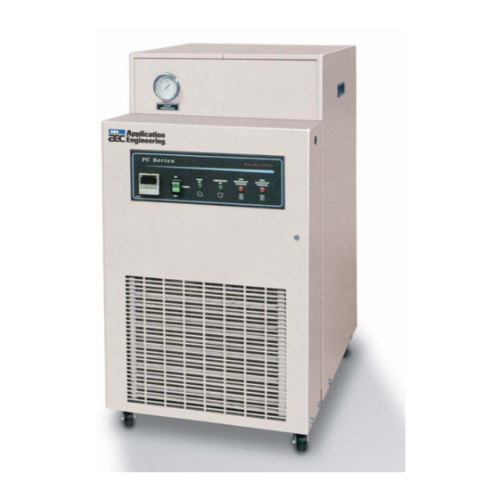
- Page 1 OPERATION AND INSTALLATION MANUAL PCA SERIES 0.5 – 1.5 hp AIR COOLED PORTABLE WATER CHILLERS IMPORTANT: PLEASE READ CAREFULLY BEFORE ATTEMPTING TO INSTALL OR OPERATE EQUIPMENT...
- Page 2 AEC, Inc. is committed to a continuous program of product improvement. Specifications are subject to change without notice. © AEC, Inc. 2008 All Rights Reserved Effective 4-29-2008 Part Number A0537986 Bulletin: AE2-615A.5 Page 2 PCA Series Chillers...
-
Page 3: Safety Considerations
Safety Considerations AEC, Inc. PCA Series Chillers are designed to provide safe and reliable operation when installed and operated within design specifications, following national and local safety codes. To avoid possible personnel injury or equipment damage when installing, operating or maintaining this equipment, use good judgment and follow these safe practices: Follow all SAFETY CODES. -
Page 4: Table Of Contents
Chiller Installation ..........13 Electrical Connections Process Water Connections PCA Condenser Air Supply Water Reservoir Overhead Process Considerations Sequence of Operation .......... 17 Chilled Water Circuit Refrigeration Circuit High Pressure Cutout Low Pressure Cutout Remote Start/Stop Interlock Page 4 PCA Series Chillers... - Page 5 PCA Startup Checklist PCA Water Circuit Pressure Drop Table Microprocessor Control......... 25 Introduction Setting the Process Water Temperature LED Indicators Temperature Controller Keys Auto-Tuning PCA Series Chillers Optional Communications Optional Graphic Panel.......... 30 Indicator Lights Switches Routine Maintenance ..........32 Lubrication Condenser Maintenance Troubleshooting Guide ..........
- Page 6 Figure 10: Piping Schematic - 1 Pump Without Reservoir............22 Figure 11: Piping Schematic - No Pump, No Reservoir............... 23 Figure 12: Typical PCA Series E5CK Microprocessor Controller..........27 Figure 13: Optional Graphic Panel ....................32 Figure 14: Typical PCA Subpanel ....................33 Figure 15: Typical PCA Wiring Schematic ..................
-
Page 7: General Information
General Information Introduction AEC, Inc.'s PCA Series Water Chillers are reliable, accurate, and easy-to-use air cooled chillers designed for use with water/glycol. Standard range of operation is 30°F (-1°C) to 65°F (18°C) for applications using glycol and 45ºF (7ºC) to 65°F (18°C) for water- only applications. -
Page 8: Available Options
75°F (24°C). Uncrating Your New Chiller PCA Series Chillers are shipped mounted on a skid, enclosed in a plastic wrapper, and open crated on all four sides and top. Pry the crating away from the skid and remove. Use a pry bar to remove the blocks securing the unit to the skid. -
Page 9: In The Event Of Shipping Damages
Notify the transportation company's local agent. Hold the damaged goods and packing material for the examining agent's inspection. Do not return any goods to AEC, Inc. before the transportation company inspection and authorization. File a claim against the transportation company. Substantiate the claim by referring to the agent's report. -
Page 10: Returns
Returns IMPORTANT! Do not return any damaged or incorrect items until you receive shipping instructions from AEC, Inc. Page 10 PCA Series Chillers... -
Page 11: Figure 1: Pca050 Process Pump Curves
PSI FEET 69 160 BZ150B BZ150C 52 120 BZ150A U. S. GALLONS PER MINUTE LITRES 10.6 12.1 13.6 15.1 16.7 18.2 19.7 21.2 22.7 24.3 25.8 PER MINUTE CURVES REPRESENT PUMP DISCHARGE ADJUSTED FOR INTERNAL BY-PASS PCA Series Chillers Page 11... -
Page 12: Figure 4: Pca Cast Iron Centrifugal Pump Curve 1/3 Hp (0.249 Kw)
Figure 4: PCA Cast Iron Centrifugal Pump Curve 1/3 hp (0.249 kW) PCA - PROCESS PUMP: CI CENTRIFUGAL TOTAL HEAD 60 HERTZ PUMP CURVE MTRS FEET Cast Iron 18.3 13.5 U. S. GALLONS PER MINUTE LITRES PER MINUTE CURVES REPRESENT PUMP DISCHARGE ADJUSTED FOR INTERNAL BY-PASS Page 12 PCA Series Chillers... -
Page 13: Figure 5: Pca Series Chiller Specifications
Figure 5: PCA Series Chiller Specifications Optional gauge package Optional gauge package Power cable entrance, either side Side cover handle Sight glass Drain plug (3/4" NPT) PUMP PRESSURE Mini Chiller PC Series Portable Chiller To Process No Flow indicator HIGH... -
Page 14: Chiller Installation
From Process Connect the chilled water return inlet to the return from the process FROM PROCESS back into the chiller for cooling and recirculation. AEC, Inc. recommends a strainer on the return line. FROM PROCESS Page 14 PCA Series Chillers... -
Page 15: Pca Condenser Air Supply
20°F/°C below the desired process setpoint. Add a pre-mixed solution to provide freeze protection to a temperature 20°F/°C below the normal operating temperature of the chiller. Use industrial quality (not automotive) ethylene glycol. PCA Series Chillers Page 15... -
Page 16: Figure 6: Ethylene Glycol Curve
A corrosion inhibitor suitable for the materials in the system should be added to the glycol/water solution. If straight water use is desired, contact the AEC, Inc. Engineering Department. The six gallon (23 liter) reservoir is not designed to withstand water pressure above 5 psi (34 kPa). -
Page 17: Figure 7: Overhead Piping
12" Check 1/8" Valve Hole 1/4" 6" Min. Process Return Strainer Process Supply Add check valve if system piping extends 15 feet above reservoir. Indicates end of AEC piping PCA Series Chillers Page 17... -
Page 18: Sequence Of Operation
75% water and 25% industrial-grade ethylene glycol with a suitable corrosion inhibitor to protect the PCA unit from freeze-up. See Figure 6 on page 16 for more information. Such damage is not covered by the AEC, Inc. warranty. Chilled Water Circuit Figure 9, Figure 10, and Figure 11 Process cooling water supply and return connections are made at the pipe stubs at the rear of the chiller. -
Page 19: High Pressure Cutout
35 psi (241 kPa) Remote Start/Stop Interlock A contact is provided to allow interlocking of the PCA Series Chiller with process controls. To use this feature, remove the jumper between Terminals X1 and 1 on Terminal Block 1. Supply a switch or dry contact interlock connected in series between these two terminals. -
Page 20: Figure 8: Pca Component Identification
Figure 8: PCA Component Identification Page 20 PCA Series Chillers... -
Page 21: Figure 9: Piping Schematic - 1 Pump With Reservoir
End of unit piping access valve Optional Temperature pressure probe gauge High pressure control Process pressure control Bypass Optional CPR valve Refrigeration Compressor access valve, Vent Fill compressor-mounted Sight glass Tank Drain Pump From Process PCA Series Chillers Page 21... -
Page 22: Figure 10: Piping Schematic - 1 Pump Without Reservoir
Condenser water piping End of unit piping Equalizing line Power element Refrigeration access valve Optional Temperature pressure probe gauge High pressure control Process pressure control Optional CPR valve Bypass Refrigeration Compressor access valve, compressor-mounted From Pump Process Page 22 PCA Series Chillers... -
Page 23: Figure 11: Piping Schematic - No Pump, No Reservoir
Equalizing line End of unit piping Power element Refrigeration access valve Optional Temperature pressure Probe gauge High pressure control Process pressure control Bypass Optional CPR valve Refrigeration Compressor access valve, compressor-mounted Flow switch From Process PCA Series Chillers Page 23... -
Page 24: Startup Checklists
4. Check the pump amp draw and pump pressure. The amp draw reading must be within the running load and service factor amps. 5. Operate the chiller, looking for leaks and listening for unusual noises or vibrations that could indicate improper operation. Page 24 PCA Series Chillers... -
Page 25: Pca Water Circuit Pressure Drop Table
PCA Water Circuit Pressure Drop Table ΔP (psig) ΔP (kPa) Model Gallons per minute Liters per minute PCA050 17.3 27.6 13.6 51.8 18.1 12.5 86.2 PCA100 17.3 17.3 13.6 20.7 18.1 34.5 PCA150 17.3 17.3 13.6 20.7 18.1 24.2 PCA Series Chillers Page 25... -
Page 26: Microprocessor Control
Microprocessor Control Introduction Standard PCA Series chillers use a microprocessor-based PID controller. The controller is a modular, self-contained unit that can slide from its mounting housing. It is factory set and adjusted; no field adjustment to the internal controls is necessary. -
Page 27: Figure 12: Typical Pca Series E5Ck Microprocessor Controller
To Process thermocouple is two degrees (2°F/ºC) below the set point. This +2°F/ºC control set point is factory-set for proper compressor operation. Changing it is not recommended without consulting the AEC Service Department. MANU LED The orange LED does not light because it is not used. -
Page 28: Temperature Controller Keys
To Process thermocouple is two degrees (2°F/ºC) above the set point. This +2°F/ºC control set point is factory-set for proper compressor operation. Changing it is not recommended without consulting the AEC Service Department. Temperature Controller Keys AT Key... -
Page 29: Auto-Tuning Pca Series Chillers
Important! Do not change any of the control settings without consulting the AEC Service Department. The AEC, Inc. warranty does not cover chiller failures from tampering with controller settings! Down Key Each press of the Down Arrow key decrements or reduces the values or settings on the display. -
Page 30: 5-6 Optional Communications
E5CK controller. When using the communications function, you must add on the unit for RS-232C or RS-485 communications. The E5CK communications function allows you to read/write parameters, do operating instructions, and select the setting level. Page 30 PCA Series Chillers... -
Page 31: Optional Graphic Panel
The compressor will stop until the flow switch senses adequate flow and restarts the chiller. Switches POWER This switch energizes the control circuit and also turns off the chiller. PCA Series Chillers Page 31... -
Page 32: Figure 13: Optional Graphic Panel
Figure 13: Optional Graphic Panel PC Series Portable Chiller HIGH PUMP COMPRESSOR REFRIGERANT REFRIGERANT PRESSURE PRESSURE POWER E5CS O RO A0537868 Page 32 PCA Series Chillers... -
Page 33: Routine Maintenance
Brush or vacuum light dirt accumulations. Avoid bending or damaging the fins. Heavy soil accumulations on the coil require professional steam cleaning; washing from the outside only makes matters worse. Figure 14: Typical PCA Subpanel Distribution Block Grounding Terminal Blocks Control Voltage Transformer Pump Condenser Contactor Contactor PCA Series Chillers Page 33... -
Page 34: Figure 15: Typical Pca Wiring Schematic
1S-1LT 1 X1 115V 1S-1LT "Power On" Pump starter "Low Refrig "Hi Refrig Pres" Pres" "Pump On" Condensing unit contactor "Compressor On" 1 10 1CNTL Jumper Legend Customer wiring/Customer-supplied components Optional components Type K Thermocouple Page 34 PCA Series Chillers... -
Page 35: Figure 16: Pca Wiring Schematic For Chillers With No Pump Or Reservoir
ON/OFF Subpanel Jumper ground 1S-1LT 115V 1S-1LT "Power On" "Low Refrig "High Refrig "No Flow" Pres" Pres" 1FLS 1FLS Condensing unit contactor "Compressor On" Legend Customer wiring/Customer-supplied components Jumper 1CNTL Optional components Type K thermocouple PCA Series Chillers Page 35... - Page 36 - Notes - Page 36 PCA Series Chillers...
-
Page 37: Troubleshooting Guide
Pump pressure is low (see Check for foreign matter. Clean the system. pump curves). Pump pressure is too high. Check for partially closed Restricted water flow. valves, etc. Be sure all lines are properly sized. PCA Series Chillers Page 37... - Page 38 Locate and repair. compressor control circuit. Unit runs continuously, but Restricted condenser Clean the condenser. not enough cooling power. airflow. Unit low on refrigerant. Call Service. Inefficient compressor. Call Service. Unit undersized for Call Sales Representative. application. Page 38 PCA Series Chillers...
- Page 39 PCA050-100 High Refrigerant Pressure Switch A0537917 PCA150 High Refrigerant Pressure Switch A0501642 PCA050-100 High Refrigerant Pressure Safety Relief Valve A0104093 PCA150 High Refrigerant Pressure Safety Relief Valve A0537974 Bronze Y Strainer * Units with the optional PCA graphic panel. PCA Series Chillers Page 39...
- Page 40 - Notes - Page 40 PCA Series Chillers...
- Page 41 - Notes - PCA Series Chillers Page 41...
- Page 42 - Notes - Page 42 PCA Series Chillers...
-
Page 43: Technical Assistance
Or call [847] 273-7700, Fax [847] 273-7812 The Parts Department at AEC, Inc. is ready to provide the parts to keep your systems up and running. AEC replacement parts ensure operation at design specifications. Please have the model and serial number of your equipment when you call.
Need help?
Do you have a question about the PCA SERIES and is the answer not in the manual?
Questions and answers