Table of Contents
Advertisement
Quick Links
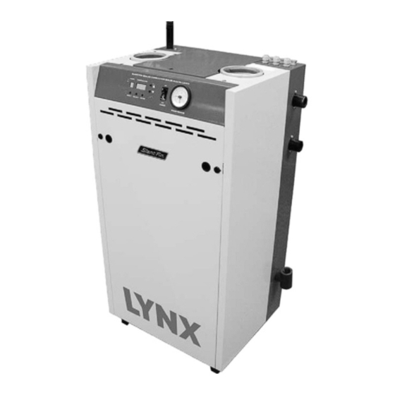
LYNX
DIRECT-VENT SEALED COMBUSTION CONDENSING BOILER
HOT WATER MODEL LX-85A
GAS-FIRED BOILER FOR NATURAL AND L.P . PROPANE GASES
INSTALLATION AND OPERATING INSTRUCTIONS
TABLE OF CONTENTS
Dimensions, Rating and Orifice Sizes .................................................2
Identification of Parts ...........................................................................3
Installation Requirements ....................................................................4
Contamination Prevention...................................................................5
Venting Application..............................................................................5
Boiler Room Air Supply and Ventilation ..............................................5
Flue gas Venting Requirements ..........................................................6
Vent Material .......................................................................................6
Air Intake Material ...............................................................................6
Vent and Air Intake Restrictions...........................................................7
Non-Direct Vent Installation .................................................................8
Sidewall Venting, Non-Direct Vent.......................................................8
Vent Termination Location and Clearance ..........................................8
Non-Direct Vent Vertical Venting .........................................................8
Direct Vent Installation .........................................................................8
Sidewall Venting, Direct Vent...............................................................8
Vent/Air Intake Termination Installation .............................................15
Direct Vent, Venting and Air Intake through a Roof ..........................16
Venting and Air Intake Regular Inspection........................................17
Condensate Removal System...........................................................17
Gas Piping .........................................................................................17
Electrical Wiring .................................................................................18
Wiring Diagram..................................................................................19
Multi Zoning .......................................................................................21
Water Piping ......................................................................................24
Operating Instructions .......................................................................30
Boiler Control Display........................................................................30
Boiler Control.....................................................................................30
Sequence of Operation .....................................................................36
Gas Input Rate Adjustment ...............................................................37
Safety Check .....................................................................................38
Care and Maintenance ......................................................................41
General Troubleshooting Guide........................................................42
Appendix A&B ...................................................................................44
The venting system of this boiler is under positive
pressure. Leakage from this system can be hazardous
and if not avoided can result in death or serious injury. In
addition to the recommendations within this manual and
the User's Information Manual, the venting system, from
the flue collector to the outdoor discharge, must be
carefully checked annually by a qualified service agency.
Heating Contractor
Address
Phone Number
Printed in Canada 0210
WARNING
IMPORTANT
READ ALL OF THE FOLLOWING WARNINGS AND
STATEMENTS BEFORE READING THE
INSTALLATION INSTRUCTIONS
WARNING
LIQUEFIED PETROLEUM (L.P .)
PROPANE GAS-FIRED BOILERS
Installation location ONLY as permitted in paragraph
entitled "LIQUEFIED PETROLEUM (L.P .) PROPANE
GAS-FIRED BOILER LOCATION" on page 4 of this
instruction book.
The above warning does not apply to NATURAL gas
fired boilers.
The installation must conform to the requirements of the
authority having jurisdiction or, in the absence of such
requirements, to the National Fuel Gas Code, ANSI Z223.1-
CSA B149.1-00 for natural gas and
latest edition or
propane
. The installation must also conform to the
additional requirements in this Slant/Fin Instruction Book.
In addition, where required by the authority having juris dic -
tion, the installation must conform to American Society of
Mechanical Engineers Safety Code for Controls and Safety
Devices for Automatically Fired Boilers, No. CSD-1 or
B149.1-00 for natural gas and propane
conflict in the above requirements, then the more stringent
requirement will apply.
WARNING
This boiler, gas piping and accessories must be
installed, connected, serviced and repaired by a
trained, experienced service technician, familiar with
all precautions required for gas-fired equipment and
licensed or otherwise qualified, in compliance with
the authority having jurisdiction.
Boiler Model Number
Boiler Serial Number
Installation Date
Part No. 84-5736 Publication No. LXA-40
C
This manual must be left
with owner and should be
hung on or adjacent to the
boiler for reference.
CSA
. If there is any
Advertisement
Table of Contents

Related Manuals for Slant/Fin LX-85A


Summary of Contents for Slant/Fin LX-85A
-
Page 1: Table Of Contents
DIRECT-VENT SEALED COMBUSTION CONDENSING BOILER HOT WATER MODEL LX-85A GAS-FIRED BOILER FOR NATURAL AND L.P . PROPANE GASES INSTALLATION AND OPERATING INSTRUCTIONS TABLE OF CONTENTS IMPORTANT Dimensions, Rating and Orifice Sizes ..........2... -
Page 2: Dimensions, Rating And Orifice Sizes
1) Primary/Secondary pumping must be used, see *Note: No orifice changes are required for high altitude installations. **See page 43 for conversion procedure to propane. pages 26/27/28. 2) A mandatory part of the set up of the Lynx is to check combustion and fuel input rate. -
Page 3: Identification Of Parts
WATER INLET HIGH (RETURN) LIMIT WATER AIR INTAKE OUTLET HOSE SENSOR WATER HEAT BOILER INLET EXCHANGER VALVE DRAIN SENSOR VALVE FLUE COLLECTOR CONDANSATE CONDENSATE DRAIN TRAP FRONT RIGHT SIDE Figure 2. Location and identification of parts (model LX-85A is shown) -
Page 4: Installation Requirements
2. See also figure 4a & 4b for mounting the boiler on the wall. B. Boiler can be installed on both combustible and non- Figure 3. Lynx boiler min. clearances for combustible combustible floors, but must NOT be installed on or above construction. -
Page 5: Contamination Prevention
Swimming pools for visual inspection. • Metal fabrication plants • Beauty shops The Lynx LX85A must be vented by an approved 29-4C • Refrigeration repair shops stainless steel venting system or by a Certified PVC or CPVC • Photo processing plants Venting system that is certified to the standard for Type BH •... -
Page 6: Flue Gas Venting Requirements
FLUE GAS VENTING REQUIREMENTS The Lynx LX-85 series boiler is a high efficiency, mechanically forced draft boiler and, therefore, requires different venting arrangements than natural draft, lower efficiency boilers. -
Page 7: Vent And Air Intake Restrictions
CPVC pipe, which may have accumulated there from the cutting process or storage. Debris can cause operational EXAMPLE: Boiler model LX-85A is to be installed. The problems with the boiler combustion components. combustion air is provided by air intake piping directly to the boiler (direct-vent installation). -
Page 8: Non-Direct Vent Installation
Lynx Model LX-85A 6. The LX-85A boiler is equipped with a built-in condensation VENT TERMINATION LOCATION AND CLEARANCES drain and trap. The trap must be filled with water. DO NOT 1. The venting system shall terminate at least 0.91m (3 feet) operate the boiler without filling the trap with water to above any forced air inlet located within 3.05m (10 feet.) - Page 9 Lynx Model LX-85A LYNX MODEL LX-85A NON-DIRECT VENT, SIDEWALL VENTING ALL JOINTS MUST BE LIQUID AND PRESSURE TIGHT. USE 76 mm (3”) DIA. PVC/CPVC SCHEDULE 40 PIPE FOR AIR INTAKE OR U/L LISTED SINGLE WALL 76 mm (3”) DIA. AL129-4C STAINLESS STEEL VENTING MATERIAL (see page 6) OR CERTIFIED PVC OR CPVC VENTING CERTIFIED TO THE STANDARD FOR TYPE BH GAS VENTING SYSTEMS, ULC S636.
- Page 10 76mm (3") DIA. CERTIFIED PVC OR CPVC VENTING PIPE OR STAINLESS STEEL VENTING MATERIAL FOR VENT Figure 9. Lynx model LX-85A - non-direct vent, venting through the roof * AL 29-4C IS A REGISTERED TRADEMARK OF ALLEGHENY LUDLUM CORP .
- Page 11 76mm (3’) DIA. CERTIFIED PVC OR CPVC VENTING PIPE OR STAINLESS STEEL VENTING MATERIAL FOR VENT Figure 10. Lynx model LX-85 - non-direct vent, utilizing an existing chimney as a chase. * AL 29-4C IS A REGISTERED TRADEMARK OF ALLEGHENY LUDLUM CORP .
- Page 12 Lynx Model LX-85A 76mm (3") DIA. 76mm (3") DIA. CERTIFIED PVC OR CPVC 76mm (3") DIA. PVC/CPVC CERTIFIED PVC OR VENTING PIPE FOR VENT PIPE FOR AIR INTAKE CPVC VENTING PIPE FOR VENT 76mm (3") DIA. PVC/CPVC PIPE FOR AIR INTAKE...
- Page 13 Lynx Model LX-85A LYNX MODEL LX-85A - DIRECT VENT, SIDEWALL VENTING ALL JOINTS MUST BE LIQUID AND PRESSURE TIGHT. USE 76 mm (3”) DIA. PVC/CPVC SCHEDULE 40 PIPE FOR AIR INTAKE OR U/L LISTED SINGLE WALL 76 mm (3”) DIA. AL129-4C STAINLESS STEEL VENTING MATERIAL (see pagE 6) OR CERTIFIED PVC OR CPVC VENTING CERTIFIED TO THE STANDARD FOR TYPE BH GAS VENTING SYSTEMS, ULC S636.s (See page 6).
-
Page 14: Alternate Sidewall Venting For Direct Or Non-Direct Venting
Lynx Model LX-85A Alternate Sidewall venting for direct or non-direct venting: Vent and/or air intake piping may be installed per figure 12a in order to provide enough clearance from snow line. Maximum allowed equivalent vent and air intake length for all of the approved vent and air intake materials is 30.48 m... -
Page 15: Vent/Air Intake Termination Installation
Lynx Model LX-85A VENT/AIR INTAKE TERMINATION FOR Certified PVC or AIR INTAKE TERMINATION FOR STAINLESS STEEL CPVC Venting AND EXHAUST FAN INSTALLATION VENTING INSTALLATION This termination is designed specifically for 76mm (3") This termination is designed specifically for the 76mm (3") -
Page 16: Direct Vent, Venting And Air Intake Through A Roof
CPVC Venting and stainless steel follow restriction on page 7 and manufacturer’s instructions. LYNX MODEL LX-85A - DIRECT VENT, VENTING AND AIR INTAKE THROUGH A ROOF ALL JOINTS MUST BE LIQUID AND PRESSURE TIGHT. USE 76 mm (3”) DIA. PVC/CPVC SCHEDULE 40 PIPE FOR AIR INTAKE ONLY. FOR VENTING USE U/L LISTED SINGLE WALL 76 mm (3”) DIA. -
Page 17: Venting And Air Intake Regular Inspection
L.P . propane gas. A manual gas supply shut-off valve is The Lynx LX-85A is equipped with a built-in condensation provided on the boiler’s gas supply pipe. (See Figure 3, drain and trap. -
Page 18: Electrical Wiring
Lynx Model LX-85A At 9.1m (30 ft.) length of pipe, match required Boiler must be electrically grounded in accordance with capacity from table on this page (choose higher the requirements of the authority having jurisdiction, or, in capacity, in this case is 4.3m /hr. -
Page 19: Wiring Diagram
Lynx Model LX-85A Figure 16a. Schematic wiring diagram. - Page 20 Lynx Model LX-85A Figure 16b. Boiler Control. Figure 16c. Ladder wiring diagram.
-
Page 21: Multi Zoning
Lynx Model LX-85A Figure 17a. Multizoning of Lynx boiler; zone valve system. MULTIZONING OF LYNX BOILER; PUMP ZONING SYSTEM USING R845A RELAY Figure 17b. Multizoning of Lynx boiler; pump zoning system using R845A relay. - Page 22 Lynx Model LX-85A Figure 17c. Multizoning of Lynx boiler; pump zoning system using R882A/B relays.
- Page 23 Lynx Model LX-85A Figure 17d. Single zoning of Lynx boiler; pump zoning system using R845A relay. Figure 17e. Single zoning of Lynx boiler; pump zoning system using R882A/B relay.
-
Page 24: Water Piping
Lynx Model LX-85A 6. LOW WATER CUTOFF 7. Water Treatment and Freeze Protection: A set of terminals is provided for connection of a LWCO. If A good water treatment program will not only extend the this device is used, remove the factory installed jumper useful life of this boiler but it will also save much of the from these terminals. - Page 25 Lynx Model LX-85A 25mm × 25mm × 19mm (1" × 1 × 3/4") NPT TEE 19mm (3/4") NPT STREET ELBOW 25mm (1") NPT STREET ELBOW WATER OUTLET (SUPPLY) PIPE 25mm (1") NPT MALE WATER INLET (RETURN) PIPE 25mm (1") NPT MALE...
- Page 26 (Boiler circulator shuts down during DHW operation) Notes: This is the minimum flow rate recommended for the model LX-85A boiler. Domestic water tank piping head is based on 25mm (1") inside diameter piping and full port valves. *** Refer to the DHW Tank Manufacturer’s water flow rate requirements and associated pressure drop head loss, to select the appropriate circulator.
- Page 27 Lynx Model LX-85A DO NOT EXCEED 305mm (12") APART EXPANSION TANK (DIAPHRAGM TYPE) Figure 20. Zoning with circulators.
- Page 28 Lynx Model LX-85A DO NOT EXCEED 305mm (12") APART EXPANSION TANK (DIAPHRAGM TYPE) Figure 21. Zoning with zone valves.
- Page 29 Lynx Model LX-85A DO NOT EXCEED 305mm (12") APART EXPANSION TANK (DIAPHRAGM TYPE) Figure 22. Piping a heating-cooling system to the boiler and a chiller.
-
Page 30: Operating Instructions
Lynx Model LX-85A OPERATING INSTRUCTIONS While “t” is blinking, DHW tank temperature may be set to desired temperature (if tank is equipped with sensor). The setting range is between FILLING AND VENTING WATER SYSTEMS 32°–71°C (90°–160°F.) A. Fill the system with water. Vent or purge of air. - Page 31 Lynx Model LX-85A Figure 23. Display Board Table 3 LYNX BOILER DISPLAY BOARD “Boiler Operation Status” MODE DESCRIPTION & TEMPERATURE DISPLAY DISPLAY Boiler is on stand-by mode. Temperature display shows supply water Temp. Space heating mode. Temperature display shows supply water Temp.
- Page 32 Lynx Model LX-85A Table 4 VIEWING AND CHANGING TEMPERATURES Press “SELECT” button for viewing different modes on “MODE DISPLAY” MODE DESCRIPTION & TEMPERATURE DISPLAY DISPLAY Space heating supply water temperature could be changed by pressing “Up/Down” button. Settable from 32°–85°C (90°–185°F) (steps of 1 F).
- Page 33 Changing priority limited time. Settable from 20 to 80 minutes. The default value is 30 minutes. Boiler model selection, value is 1 for model LX-85A Boiler model confirmation, value is 1 for model LX-85A Weather compensation supply water reference temperature (space heating mode 1 or 2).
- Page 34 Lynx Model LX-85A 90°C 80°C 60°C 50°C 40°C 30°C Water reference temp (default of 20°C 30°C [86°F]) 10° 0° -10° -20° -30° 0°C 20°C Figure 24. Space Heating mode with outside sensor water set point graph.
- Page 35 Force or attempted repair may result in a fire Lynx LX-85A boiler under the ANSI Z21.13 - latest edition and or explosion. CSA-B149.1-00 for natural gas and propane.
-
Page 36: Sequence Of Operation
Lynx Model LX-85A LYNX BOILER MODEL LX-85A SEQUENCE OF OPERATION THERMOSTAT CALLS FOR HEAT CIRCULATOR(S) ON COMBUSTION BLOWER ON (AT MEDIUM SPEED) CONTROL LOCKOUT BLOWER SPEED CONFIRMED? DISPLAY SHOWS ERROR “A 33” 5 SECOND PRE-PURGE PERIOD CONTROL LOCKOUT DISPLAY SHOWS ERROR “A 01”... -
Page 37: Gas Input Rate Adjustment
Lynx Model LX-85A IV. CHECK COMBUSTION AND FUEL INPUT RATE Increasing the blower rpm will increase the fuel input rate, and decreasing the blower rpm will decrease the A. Remove the boiler jacket front panel, by turning the 2 fuel input rate. -
Page 38: Safety Check
Lynx Model LX-85A Increasing the blower rpm will increase the fuel input B. Thermostat Test: rate, and decreasing the blower rpm will decrease Set thermostat setting to low enough to end call for heat. the fuel input rate. Gas valve should close and burner should stop firing. - Page 39 Lynx Model LX-85A B. BLOCKING ERRORS: Indicated by an “E” in the mode display. Operation is automatically restored, once the condition returns to normal or is fixed. The temperature display shows the error code. Pressing the “Reset” button is not required.
- Page 40 Lynx Model LX-85A continued from page 38 ERROR CODE INDICATION REMEDY Check flue gas temperature, at the maximum firing rate and high water temperature. If the flue gas temperature reaches 100°C (212°F), check the fuel input rate and Excess Flue Temperature combustion.
-
Page 41: Care And Maintenance
Refer to Parts should not occur. List for LX-85A for replacement parts part numbers. When ever 4. Low water cutoff for operation (see instruction possible refer to the original order by number and date. -
Page 42: General Troubleshooting Guide
Lynx Model LX-85A GENERAL TROUBLESHOOTING GUIDE FOR SERVICE PERSONNEL WARNING: Only a trained, experienced service technician should perform troubleshooting. Turn off all electrical power to the boiler before servicing. BURNER FAILS TO OPERATE - NO HEAT CAUSE REMEDY 1. No power, display off, power switch off. Main electric 1. - Page 43 Lynx Model LX-85A...
- Page 44 Lynx Model LX-85A APPENDIX A Thermostat Heat Anticipator Settings Fixed anticipator thermostats are not adjustable. The lower the anticipator setting (toward .18) the faster the thermostat will respond to a change in room temperature. Adjustable anticipator thermostats, depending on thermostat Too low a setting and the boiler will short cycle.
Need help?
Do you have a question about the LX-85A and is the answer not in the manual?
Questions and answers