
Related Manuals for LG Central Air Conditioning Remote Condensing Unit


Summary of Contents for LG Central Air Conditioning Remote Condensing Unit
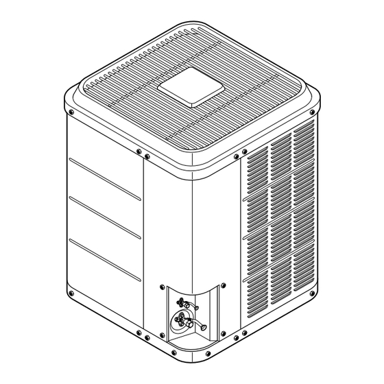
- Page 1 Installation Instructions & Use and care MANUAL LG Central Air Conditioning Remote Condensing Unit...
-
Page 2: Installation Instructions
Installation Instructions Attention Installer: System installer’s guide Check list (Page 11.) shall be completed as per instructions These Instructions Should be carefully read and kept with the production for future reference... -
Page 3: Table Of Contents
CONTENTS INSTALLATION SAFETY ................................2 SHIPPING INSPECTION ............................3 UNIT DIMENSIONS ..............................3 MINIMUM CLEARANCES ............................3 INSTALLATION LOCATION ..........................3 REMOVING EXISTING CONDENSING UNIT ......................3 REFRIGERANT HANDLING ..........................4 LINE SET INSTALLATION...........................4 INSTALLATION ..............................5 METERING DEVICES............................5 BRAZING CONNECTIONS ..........................5 LEAK JESTING ..............................5 EVACUATION...............................6 LINE SET REFRIGERANT(CHARGE) ADJUSTMENT AND RELEASE OF CHARGE ........7 ELECTRICAL................................7 CONDENSING UNIT WIRING DIAGRAM ......................8 SYSTEM START-UP / FINAL CHARGE ADJUSTMENT..................8... -
Page 4: Shipping Inspection
SHIPPING INSPECTION This product was carefully inspected at the factory and released to the transportation company with no known damage. Inspect carton for damage to help locate potential areas of damage. Remove carton and inspect entire unit for damage. If damage is found, report it immediately to the carrier. UNIT DIMENSIONS Physical Data, 12 SEER Models Table 1... -
Page 5: Refrigerant Handling
REFRIGERANT HANDLING • Warning! Do not sniff or inhale refrigerant. Personal injury or death may occur. • Warning! Avoid contact with liquid refrigerant. Wear gloves and safety glasses to avoid frost- bite and blindness. • Warning! Never apply flame to refrigerant cylinder. Possible explosion resulting in personal injury or death is possible. -
Page 6: Installation
• Do not make direct contact with ductwork, floor joists, wall studs, walls, and plumbing. • Leave slack between building and unit to avoid vibration transmission. • Seal wall penetration with RTV or other suitable caulk. • Do not strap line set to joists with wire or strapping in direct contact. •... -
Page 7: Evacuation
LEAK TESTING 1. Close hand valves on gauge set. 2. Attach gauge hoses to service valve ports. 3. Keep service valves closed. 4. Connect nitrogen cylinder to center port on gauge set. 5. Open nitrogen cylinder valve slightly. 6. Open high pressure valve on gauge set. 7. -
Page 8: Line Set Refrigerant(Charge) Adjustment And Release Of Charge
LINE SET REFRIGERANT(CHARGE) ADJUSTMENT AND RELEASE OF CHARGE Condensing units are factory-charged with enough refrigerant for typical evaporator coil sizes and 25 feet of line set tubing. Refer to Table 4 for proper refrigerant adjustment. Table 4 Liquid Line OD (in) Adjustment (oz/ft) 1/4"... -
Page 9: Condensing Unit Wiring Diagram
CONDENSING UNIT WIRING DIAGRAM Power Supply Condenser Black Motor Yellow Ground Capacitor Yellow Black Contactor Compressor • Indoor Air Handler • Gas Furnace CONDENSING UNIT Factory Wiring 208/230VAC, 60Hz Field Wiring 208/230VAC, 60Hz Field Wiring 24VAC, 60Hz Fig. 7 SYSTEM START-UP / FINAL CHARGE ADJUSTMENT •... -
Page 10: Final Charge Adjustment
Table 5 Table 6 Saturated Suction Temperature (R-22) Saturated Suction Temperature (R-22) Suction Pressure Saturated Suction Suction Pressure Saturated Suction (PSIG) Temperature (˚F) (PSIG) Temperature (˚F) 60.1 195.9 62.8 210.7 65.6 68.5 229.5 71.4 239.3 74.5 249.4 77.6 259.8 80.7 270.5 281.6 87.3... -
Page 11: Final Checks
FINAL CHECKS Verify that all wiring is secure and routed properly. Check that all tubing is sound. Caution! Compressor dome may be hot! Don't touch compressor dome. Securely fasten all panels and covers. Leave Use and Care Manual with homeowner. Discuss operation and routine maintenance with homeowner. -
Page 12: System Installer's Guide - Check List
SYSTEM INSTALLER’S GUIDE - CHECK LIST CHECKOUT PROCEDURE (After completion, review and leave with home owner or as directed) Date of Installation Model Number Serial Number Installing Contractor Name Installing Contractor Phone Number After installation has been completed, it is required that the entire system be checked against the following list: 1. - Page 13 13. Is the refrigerant tubing properly supported by isolation hangers? 14. Has the system been properly evacuated? 15. Is the outdoor unit protected by the correct size time delay type fuses or breakers in the indoor electrical panel? 16. Are the power supply wires to units the correct size? 17.
- Page 14 SYSTEM OPERATIONAL CHECK IMPORTANT: To prevent compressor damage which may result from the presence of LIQUID refrigerant in the crankcase, these procedures should be followed at initial Start-Up and at anytime the power has been off for 12 hours or more if the compressor uses a crankcase heater. 1.
-
Page 15: Use And Care Manual
Use and Care Manual Thank you for your purchase of this air conditioning unit. This air conditioning unit has been carefully designed, built, and tested to ensure many years of energy-efficient comfort. SAFETY • Understand the following safety terms: o Danger! - Identifies hazards that will result in personal injury or death. o Warning! - Identifies hazards that could result in personal injury or death. - Page 16 COOL - In this mode the house will be cooled if the desired temperature is below the actual inside temperature. AUTO - In this mode the house will be heated or cooled when the inside temperature of the house falls outside a specified range.
- Page 17 electrical shock. Electrical shock may cause personal injury or death. Caution! Although sharp edges have been minimized in the unit, • Open door/panel to access filter. be careful when reaching into unit or touching/handling parts. • Change/clean filter • Close door/replace panel •...
-
Page 18: Limited Warranty
6. Damages cause by inadequate supply of air. 7. Damages resulting from running the product in a corrosive atmosphere. 8. Repairs when your LG product is used in other than normal, single-family household use or contrary to the instructions outlined in the product owner’s manual.
Need help?
Do you have a question about the Central Air Conditioning Remote Condensing Unit and is the answer not in the manual?
Questions and answers