Table of Contents
Advertisement
Advertisement
Table of Contents

Related Manuals for Lavry AD122-96 MX


Summary of Contents for Lavry AD122-96 MX
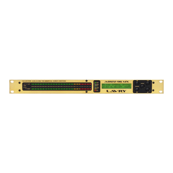
- Page 1 Model AD122-96 MX Master Analog to Digital Converter Operations Manual...
- Page 2 Lavry Engineering, Inc. P.O. Box 4602 Rolling Bay, WA 98061 (360)598-9757 http://www.lavryengineering.com email: techsupport@lavryengineering.com Revision 1.0 March 1 2013...
- Page 3 “clean clipping,” the MX model extends the useful range of clipping to even higher levels. The MX model retains the Lavry exclusive Soft Saturation modes which increase the level below the saturation threshold by a selectable 3 or 6db. Audio signals above the threshold are processed by an emulation of analog tape saturation without artifacts associated with attack and release times.
- Page 4 AD122-96 MX Operations Manual This page left blank. intentionally.
-
Page 5: Limited Warranty
Subject to the conditions set forth below, for one year after the original purchase date of the product, Lavry Engineering will repair the product free of charge in the United States in the event of a defect in materials or workmanship. -
Page 6: Table Of Contents
Specifications ..................11 Appendix I αβC αcoustic βit Correction™ ............. 12 Noise-Shaping Curves ............... 15 Appendix II AD122-96 MX Input Considerations ..........16 Appendix III AD122-96 MX Soft Saturation ............18 Appendix IV Viewing Noise Floor on AD122-96 MX Display ......20... -
Page 7: Part I Introduction
Operations Manual PART I: Introduction The Model AD122-96 MX Master Analog to Digital Converter receives analog input signals at the left and right analog input channels. The converter can receive balanced or unbalanced analog input signals. Individual left and right analog gain adjustment can be made via the front panel adjustment pots. Fine tuning of reference levels can be achieved by setting the front panel bar graph display (LED's) to “Fine”... -
Page 8: Operating Instructions
Operations Manual Operating Instructions Operation of the Model AD122-96 MX Master Analog to Digital Converter requires the use of five push button switches located on the front panel. The liquid crystal display is organized for a quick and intuitive operator interface. The unit features six screen displays. -
Page 9: Main Screen
AD122-96 MX Operations Manual Main Screen The main screen is used for selecting the A to D clock source and output word length parameters. The top line controls the A to D clock source: 44.1kHz INTERNAL CRYSTAL 24 BITS WL ABC:OFF... -
Page 10: Word Length And Acoustic Bit Correction
AD122-96 MX Operations Manual αcoustic βit Correction™ Word Length and The bottom line controls word length and αcoustic βit Correction™ parameters: 44.1kHz INTERNAL CRYSTAL 20 BIT WL ABC: HPDF Setting Word Length: The selection of word length (16 to 24 bits) sets the digital output word length. The NI setting (word length not indicated) is a 20 bits default setting as per AES/EBU specifications. -
Page 11: Audio Control Screen
It is still possible to clip the signal if enough signal level is applied to the analog inputs. DC offset removal: The Model AD122-96 MX converts signals down to DC (0Hz). The total DC offset (due to DC offset within the audio signal and the offset of the converter itself) can be removed. -
Page 12: Bar Graph & Display Screen
11dB higher than the rms noise for flat noise spectrum. 3. Measuring the converter noise floor is best done with specialized equipment (such as Lavry Engineering’s Model LE3000S). To verify the proper converter noise floor via extended metering you must activate the DC removal (DC REMOVAL ON) and connect a low value resistor (0-1k Ohm) between pins 2 and 3 of the analog input XLR connector. -
Page 13: Warm-Up And Calibration
AD122-96 MX Operations Manual Warm-up and Calibration The recommended warm up time is 15 minutes. The AD122-96MX feature self-calibration for consistent long-term accuracy. A complete calibration cycle (about 5 seconds in duration) is activated at power on. A calibration cycle may be initiated by pressing both the EXIT and GO buttons simultaneously. -
Page 14: Hardware Interconnections
ONLY at the very end of the chain. Maintenance The Model AD122-96 MX is an auto calibrating converter requiring no periodic adjustments. The unit generates a significant amount of heat (25 watts maximum). The temperature rise is no cause for concern, but allowing for some airflow is always a benefit from a long-term reliability standpoint. -
Page 15: Part Ii Specifications
AD122-96 MX Operations Manual Specifications Part II: Analog Inputs: The analog signal can be amplified by 0-12dB utilizing the front panel screw adjust trim pots. Full- scale signal with 0dB gain is 24dBu, (full-scale signal with 12dB gain is 12dBu). -
Page 16: Αβc Αcoustic Βit Correction
The Model AD122-96 MX offers High Pass or Flat Dither type and four noise-shaping curves. Model AD122-96 MX allows the user to use dither with or without noise shaping. Operating noise shapers without dither is undesirable so the unit automatically shuts the noise shaper off when dither is off. - Page 17 (8-12 bits) should be avoided. The ideal noise-shaping curve may be irritating at loud levels. Lavry Engineering’s listening tests were based on test tones and repeating loops of quiet passages of various material (mostly classical music) with flat amplifier response. Listening to test tones was straightforward: we used the Model AD122-96 MX test tone generator mode switching the αcoustic...
- Page 18 AD122-96 MX Appendix I Figure 5 shows αcoustic βit Correction™ (High Pass, NS2) applied to a 24 bit input, reducing to 16, 18, 20, and 22 bit output widths. Notice that there is no noise modulation present. Figure 6 shows the effect of high-pass triangular dither only. The more coherent data in the dithered bits, the better the dithering process works.
-
Page 19: Noise-Shaping Curves
AD122-96 MX Appendix I Noise-Shaping Curves Figure 11 compares Flat dither with NS2, NS3, and NS4 noise- shaping curves. Note the increasing aggressiveness of the curves, with the pronounced dip at 4kHz and in the 12kHz region. These correspond to the most sensitive areas of the ear to noise. -
Page 20: Appendix
AD122-96 MX Input Range: You may suspect by now that our aim is to provide you with an A/D converter and leave the problem of providing a "hot" signal at the hands of microphone and mic- preamplifier manufacturers. - Page 21 AD122-96 MX Appendix II Note: Much information is available regarding proper shielding. The well known book "Grounding And Shielding in Instrumentation" by Ralph Morrison provides an excellent explanation of the subject and points out clearly that the floating shield connection is the correct configuration. Engineers using the grounded configuration with 16-17 bit systems may wish to re-evaluate their interconnections for 20 bit systems.
-
Page 22: Appendix Iii Ad122-96 Mx Soft Saturation
AD122-96 MX Appendix III Appendix III: AD122-96 MX Soft Saturation The SOFT SATURATION feature provides a digital emulation of an ideal magnetic tape saturation characteristic. The three available settings are: 1. SOFT SATURATION OFF: yields normal converter operation (see lower curve VOFF). - Page 23 AD122-96 MX Appendix III Below are time domain plots for the +3dB setting (left plot) and +6dB setting (right plot). Each plot shows the transformation of two input signals (dotted lines) to two output signals (solid lines). The settings provide different tradeoffs between gain and "peak signal distortion".
-
Page 24: Viewing Noise Floor On Ad122-96 Mx Display
Gaussian noise energy is measurable via a rms. (root mean square) meter. The proper measurement of converter noise should be done using a rms. instrument (such as Lavry Engineering’s Model 3000, Audio Precision test system or others). However, the known bell shaped curve coupled with a peak reading offers a reasonable and quick estimate of the rms. - Page 25 AD122-96 MX Appendix IV Such measurement and calculation may aid in evaluating the noise of a driver device, or a series of devices. The distribution due to addition of Gaussian signals is still Gaussian. While the 8dB "translation factor" is true for Gaussian noise, it does not hold true for non-Gaussian noise. Such factor is 3dB for sine waves and 0dB for square waves.
Need help?
Do you have a question about the AD122-96 MX and is the answer not in the manual?
Questions and answers