Table of Contents
Advertisement
Advertisement
Table of Contents

Subscribe to Our Youtube Channel
Related Manuals for RM C-Series


Summary of Contents for RM C-Series
- Page 1 C-Series User Manual...
- Page 2 Computer Details Fill in the details of your computer for quick reference: Model Description (see front of computer): ..........Part Number (see rear of computer): ..........Serial Number (see rear of computer):WO/TO/MO ..……..…....Customer Account Number (see despatch note):........... Graphics: ..........
- Page 3 C-Series User Manual Edition 1 Copyright © Research Machines plc 1999. All rights reserved. Although you may make copies of this manual for your own use, you may make no other form of copy of any part of it without our written permission.
-
Page 5: Table Of Contents
Contents Introduction Safety Plugs and Sockets Cables Fuses Ventilation and Dust Protection Other Precautions Conventions Used in this Manual Chapter 1 Getting Started Before you Start Disks and Manuals Setting up the Computer Security Considerations Environment Considerations Looking after Yourself Starting Up Chapter 2 System Description Variations between Models... - Page 6 Contents Connecting to a Printer Compatibility Choosing a Printer Setting up a Printer How to Select the Printer Setting Serial Communication Parameters Testing your Printer Connecting to a Network Chapter 3 Fitting Hardware Options Internal Structure of the Computer The Cover of the Computer Removing the Cover Replacing the Cover Protecting Against Static Electricity...
- Page 7 Contents Hard Disk Problems Error Messages During Start-up Before you Ring for Help Chapter 5 Technical Information General Specification System Board Power Requirements Battery Physical Specifications Safety Ergonomics Electro-Magnetic Compatibility (EMC) Environmental Factors Connectors Video Signal Connector Monitor Power Connector Serial Connector Parallel Connector Mouse and Keyboard Connector...
-
Page 9: Introduction
Refer to this manual whenever you need further information on how to operate your computer. This Windows icon is the ‘RM PC Help’ icon which loads the RM PC help file. This file is pre-installed on all C-Series computers with a ™... -
Page 10: Safety
On the 1st January 1996 the new Electromagnetic Compatibility Directive (89/336/EEC) became a legal requirement on all electrical and electronic equipment. RM products comply fully with this European Directive. The relevant standards are EN50082-1 and EN55022 and these refer to: •... -
Page 11: Plugs And Sockets
Never replace a blown fuse with one of a higher rating than the correct fuse. Ventilation and Dust Protection Your C-Series computer has a cooling fan outlet on the rear panel and ventilation slots on the underside of the front panel. Always make sure that all the ventilation outlets are not obstructed, to prevent your computer from overheating. -
Page 12: Other Precautions
Warranty claims made for defects arising from failure to comply with this instruction will not be entertained by RM or their suppliers of third party components. -
Page 13: Conventions Used In This Manual
Introduction • Do not tamper with the power supply unit. • Do not move the computer while it is switched on. If you want to move the computer, always switch it off and wait for a minute to allow the hard disk(s) to stop rotating. •... - Page 14 Introduction...
-
Page 15: Chapter 1 Getting Started
1. Before you start. 2. Disks and manuals. 3. Setting up your computer taking into account security and the environment. RM also runs various training courses. Contact the RM Training Administrator on Abingdon (01235) 826125 for details. -
Page 16: Before You Start
• Customer Account Number The despatch note has your customer account number printed on it. You will need this number if you ever need to call RM. Make a note of the number on the inside front cover of this manual (or another suitable place). -
Page 17: Disks And Manuals
Master disks or CDs may be supplied depending on the model. • • On-line documentation If a hard disk drive is fitted, RM provide an on-line help file on the Windows desktop. The operating system software has its own on-line help files and any additional software such as Microsoft®... -
Page 18: Security Considerations
Security Considerations Theft of computers or components is becoming more common so RM recommend you implement all secure practices. Security products are available, e.g. security cable and padlock; for information on the full range please call the Education Sales Desk on (01235) 826868. -
Page 19: Environment Considerations
1: Getting Started Environment Considerations Power Supply Place the computer near to a power point to avoid trailing cables. If you do use an extension lead make sure it is three-core and safely earthed. Avoid connecting the computer to a power supply that is shared with heavy-duty equipment (such as hydraulic lifts, vacuum cleaners and lathes) or portable tools. - Page 20 1: Getting Started Temperature Avoid placing your computer in an environment that is damp or dusty as this will shorten the working life of the computer. Do not place the computer where it will have prolonged exposure to direct sunlight. Avoid extremes of temperature (below 5°C and above 35°C).
-
Page 21: Looking After Yourself
1: Getting Started Looking after Yourself • Make sure that you have enough space for all your paperwork and manuals. A document holder may help to avoid awkward neck movements. • Adjust your chair and monitor so that you find the most comfortable position. -
Page 22: Starting Up
1: Getting Started Starting Up Unpack your computer carefully and save all the packaging in case you need to move the computer at a later date. If you place a monitor on top of your computer, put it down gently. Place it centrally if you can. - Page 23 1: Getting Started...
-
Page 25: Chapter 2 System Description
Chapter 2 System Description This chapter describes various aspects of your C-Series computer. It covers: • the exterior of the computer • using floppy disks • using hard disk and CD-ROM drives • the keyboard and special keys • the mouse •... -
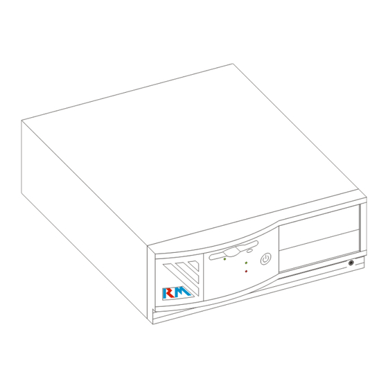
Page 26: The Front Of The Computer
2: System Description The Front of the Computer FDD LED Eject Button Power switch Power LED HDD LED Power switch The power switch is used to switch the computer on and off. If you switch off the computer using the power switch, wait about five seconds before switching on again. - Page 27 2: System Description 3½ inch floppy disk drive The floppy disk drive fitted in the computer uses standard 3½ inch disks. To insert a disk, push it into the shuttered slot until it clicks into place. Floppy disk drive LED This is lit when the computer is accessing the disk in the floppy disk drive.
-
Page 28: The Rear Of The Computer
2: System Description The Rear of the Computer These features can be identified at the rear of the computer: Expansion Slots Mains power System board connector I/O panel Note: Not all connectors are shown here. I/O connectors may appear in any position in the I/O panel and additional connectors may appear in any of the expansion slots according to the model. - Page 29 Make sure that you record the serial number onto the inside front cover of this manual for security purposes. The serial number also identifies your computer model. If you contact RM, you may be asked for this number. Voltage specification label...
- Page 30 2: System Description I/O connectors The mouse, serial, parallel and keyboard connectors are fitted to I/O connector positions. These connectors are labelled. See page 76 for diagrams of these connectors. Mouse connector This is a 6-pin IBM PS/2 connector for use with a PS/2 style mouse.
-
Page 31: Using Disks And Disk Drives
2: System Description Using Disks and Disk Drives A disk is a magnetic storage device which holds information such as computer programs and data. The computer uses disk drives to write information to a disk and to read information from the disk. There are three types of disk drives: hard disk drives (HDD), floppy disk drives (FDD) and compact disk drives (CD-ROM drives). - Page 32 There is additional help on backing up in RM PC Help. Caring for your hard disk Take care of your hard disk. It is fragile and may be damaged if accidentally knocked or jolted.
-
Page 33: Floppy Disks
2: System Description Floppy Disks A 3½ inch floppy disk can be inserted into and removed from your computer. The floppy disk drive fitted in your computer is a 1.44 MB 3½ inch disk drive. The 1.44 MB 3½ inch drive accepts two types of 3½ inch disks: •... - Page 34 Always make backups (copies) of programs and data which are important to you. Store the backup in a safe place. There is additional help on backing up in RM PC Help. Labelling floppy disks Always label your disks carefully so that you know which files they contain.
- Page 35 2: System Description Preparing new floppy disks for use New disks must be prepared for storing information. To do this, you run a program which formats the disk so that the operating system can store and find information on it. Beware: Formatting a disk destroys any information held on the disk Be very careful when you format a disk.
-
Page 36: Cd-Rom Drives
2: System Description CD-ROM Drives A CD-ROM drive is used for reading compact disks (CD’s). It will be built into the spare drive bays. CDs are used as mass storage devices because you can store huge amounts of data on them. Looking after your CDs We advise you try to keep the CDs in their original packaging. -
Page 37: The Keyboard
2: System Description The Keyboard The keyboard is used to type instructions and enter information into the computer. The keyboard supplied with your system is a Windows 95 105-key keyboard (see page 79 for pin-out of connector). You can adjust the keyboard to two different working positions using the fold-away legs on the underside of the keyboard. -
Page 38: Typewriter-Like Keys
2: System Description Typewriter-like Keys The layout of the typewriter-like keys is similar to that of a standard typewriter, as shown below: The normal actions of these keys are similar to those on a typewriter: when you press an alphabetic key, the lower-case letter appears. - Page 39 2: System Description Press if you want the alphabetic keys <Caps Lock> to produce upper-case letters. The Caps Lock indicator LED lights to show that <Caps Lock> been pressed. Using has no effect on <Caps Lock> non-alphabetic keys. To return the alphabetic keys to lower-case mode, press again.
-
Page 40: Function Keys
2: System Description key can be used in certain <Print Scrn> circumstances to print the screen display, if the computer is connected to a printer. Pressing the key causes the <↑> <Scroll Lock> and <↓> arrow keys to move the text displayed on screen up or down one line. -
Page 41: Numeric Keypad
2: System Description These keys are used to carry out particular functions, or tasks. The function depends on the software you are running. Numeric Keypad The numeric keypad is located to the right of the main keyboard as shown above. These keys can be used as either cursor movement keys or number keys. -
Page 42: Special Keypads
2: System Description Special Keypads The keyboard has separate cursor movement keys to the left of the numeric keypad. These keys can be used to move the cursor even when the numeric keypad is set to produce numbers. Key Combinations keys can be used in combination with other <Ctrl>... -
Page 43: The Monitor
Your computer is supplied with a Super VGA (video graphics array) display adapter. You can use a VGA, or Super VGA monitor (in various sizes) with your computer. Contact RM for more information on monitors or consult your RM Sales catalogue. -
Page 44: Connecting To A Printer
SVGA adapter. There is additional help on setting up resolutions and refresh rates to match your monitor in the RM PC Help. Connecting to a Printer Printers must be carefully selected to produce the output you want. -
Page 45: Choosing A Printer
2: System Description Choosing a Printer The range and quality of work produced on a printer varies with the type of printer you choose. We advise you to use a parallel printer, rather than a serial printer, if possible. Parallel printers are easier to set up and use than serial printers. -
Page 46: How To Select The Printer
How to Select the Printer There is help on installing printers in the RM PC Help. You can also set the printer as default for all Windows applications by selecting the ‘Set As Default’ button. -
Page 47: Setting Serial Communication Parameters
2: System Description Setting Serial Communication Parameters The following settings must have the same values on your computer as they do on the serial printer: • baud rate • parity setting • word length (or number of data bits) • number of stop bits Find out the printer settings from your printer manual. -
Page 48: Connecting To A Network
2: System Description Connecting to a Network A network is a number of computers which are connected together. These computers can share applications and exchange data. The network consists of a server and at least one network station. The server stores the software and the users' files; the network station is a computer used by anyone wanting to access the information and applications on the server. -
Page 49: Chapter 3 Fitting Hardware Options
• How to fit and remove disk drives. Selecting options A full list of the options that can be purchased from RM is given in the RM Systems price list. Before buying an upgrade from a manufacturer other than RM, we advise you to contact RM to ensure that the option you intend to buy is suitable for use with your computer. -
Page 50: Internal Structure Of The Computer
3: Fitting Hardware Options Internal Structure of the Computer The internal structure of the C-Series computer can vary depending on the model. The system board may vary in each model so each system is supplied with a software copy of it’s own System Board User’s manual. -
Page 51: The Cover Of The Computer
3: Fitting Hardware Options The Cover of the Computer Removing the Cover Toolbox: Pozidriv no. 1 screwdriver 1. Switch off your computer and unplug it from the mains. 2. Remove the security cable or padlock (if fitted). Switch off, unplug and disconnect all attached equipment (including the monitor, mouse, keyboard and any network cable(s)). -
Page 52: Replacing The Cover
3: Fitting Hardware Options Replacing the Cover Toolbox: Pozidriv no. 1 screwdriver 1. Make sure that all the internal cables are tucked safely out of the way, so that they will not be caught between the cover and the internal frame. 2. -
Page 53: Protecting Against Static Electricity
3: Fitting Hardware Options Protecting Against Static Electricity STATIC WARNING: Before handling any of the components in the computer, take precautions against damage caused by static electricity on your body. If you have an earthing wristband, attach it to the power supply unit. -
Page 54: Adapter Cards
3: Fitting Hardware Options Adapter Cards You can enhance the capabilities of your computer by inserting adapter cards into the bus expansion slots. 16-bit ISA (Industry Standard Architecture) cards or PCI local bus cards (full-size or half-size) can be fitted in the computer using the expansion slots. The positioning of the adapter cards may vary so refer to the expansion label for identification of the various adapter cards. -
Page 55: Handling Adapter Cards
3: Fitting Hardware Options Handling Adapter Cards STATIC WARNING: Ensure that cards and chips are not damaged by static that builds up on your body. • If you have an earthing wristband, put it on before touching any card or chip (see page 45). •... -
Page 56: Fitting A Card
3: Fitting Hardware Options Fitting a Card Toolbox: Pozidriv no. 1 screwdriver 1. Remove the cover (see page 43). 2. Select a slot that is appropriate for the card, e.g. ISA, or PCI local bus. Note: The position of the different types of expansion slots are in your System Board User’s manual (supplied). - Page 57 3: Fitting Hardware Options 7. Plug in any cables or leads you may need. Refer to the manufacturers instructions provided. 8. Replace the cover of the computer (see page 44).
-
Page 58: Removing A Card
3: Fitting Hardware Options Removing a Card Note: If you need to remove any cables please make a note of the orientation BEFORE removal. Toolbox: Pozidriv no. 1 screwdriver 1. Remove the cover (see page 43). 2. Disconnect any cables connected to the card making a quick sketch of their orientation and where they plug into. -
Page 59: Dimms
Your computer may use Dual In-line Memory Modules (DIMM) to provide random access memory (RAM). All C-Series computers are supplied with a minimum 16 MB of RAM. The system board in your computer can be upgraded using the additional sockets available. -
Page 60: Fitting A Dimm
3: Fitting Hardware Options Fitting a DIMM These instructions refer to fitting a DIMM. N.B. The retention mechanism on the sockets may vary from those illustrated. 1. Remove the cover (see page 43). 2. Hold the DIMM at a 90° angle to the empty socket with the notches on the DIMM aligned with the notches on the empty socket. - Page 61 3: Fitting Hardware Options 3. Keeping the DIMM at this angle, slide it between the slots at each end of the DIMM socket it horizontal and at a 90° to the socket. Press the DIMM firmly into the socket, the retaining clips will ‘click’...
-
Page 62: Removing A Dimm
3: Fitting Hardware Options Removing a DIMM 1. Remove the cover (see page 43). 2. Using your fingers, push the plastic retaining clips down and away from the DIMM to release it from the socket. The released DIMM can then be lifted up and out of the slots at either end of the DIMM socket. -
Page 63: System Board Upgrades
All processors are fitted in to a ZIF (Zero Insertion Force) socket for easy removal and upgrading. If you wish to purchase any of these upgrades, contact the RM Sales Desk for more details. Fitting a Processor Note: You WILL need your System Board User’s Manual. -
Page 64: Drive Upgrades
5. Check on start-up that the correct processor type and speed is detected. Drive Upgrades Your C-Series computer can have a number of different drive upgrades. There is space for up to two external drives. The external drive upgrades could be any of the following:- •... - Page 65 3: Fitting Hardware Options 1. Unscrew and remove the metal EMC screening plate which is across the front of the drive bay. You no longer need the EMC screening plate but keep it in case you want to remove the drive in the future. 2.
-
Page 67: Chapter 4 Maintenance, Service And Troubleshooting
• Problem solving - if things go wrong and you cannot sort out the problem contact RM Customer Support. There is a current list of phone numbers in RM PC Help. Looking After Your Computer If you do not use the computer for a while, protect it with a dust cover. -
Page 68: Moving And Re-Packing The Computer
Do not use a damp cloth to clean floppy disks. Do not attempt to clean the interior of the computer. This service should only be performed by a fully qualified RM technician. Moving and Re-packing the Computer If you need to move your computer a short distance - to an adjoining room for example - disconnect all equipment connected to the computer. -
Page 69: Servicing
• the mains lead appears frayed or damaged • the computer behaves abnormally If you need to return the computer to RM, make a new backup of all the contents on the hard disk (if fitted) and keep these copies in a safe place. -
Page 70: Problem Solving
4: Maintenance, Service and Troubleshooting Problem Solving Keep a note of what happens when you carry out the checks in this chapter. If the checks do not help, turn to page 70 for what to do next. Computer The green power light does not come on when you switch on the computer. -
Page 71: Mouse
4: Maintenance, Service and Troubleshooting • Have you tried another keyboard (if possible)? Mouse The mouse does not work. • Check the mouse is plugged into the correct port. • Check you have the correct mouse drivers loaded if required. Peripherals (Printers and other Input/Output devices) Equipment connected to your computer does not work. -
Page 72: Software
4: Maintenance, Service and Troubleshooting • Is your monitor switched on at the power source and the monitor? Most monitors have an "on" light. Note: Some monitors need the monitor signal cable plugged in to the computer and the computer switched ON before the monitor will power up. If the monitor is not receiving a signal from the computer the “on”... -
Page 73: Forgotten Passwords
RM to be reset. This reset is not covered by your warranty agreement. CHOOSE A PASSWORD WHICH YOU WILL REMEMBER. Since RM will need to ensure you are the owner, you may need to provide some further identification, to prevent unauthorised access to your computer. -
Page 74: Hard Disk Problems
4: Maintenance, Service and Troubleshooting Hard Disk Problems This section provides some guidance on investigating problems with the hard disk. You should make sure when trying to solve hard disk problems that you do not erase important files unnecessarily. Note: Make regular backups of files on the hard disk and keep backup disks of applications. -
Page 75: Error Messages During Start-Up
If so, see the problem explanation below. • If you cannot access any of the information on the hard disk, contact RM. You cannot start up using the hard disk but can access the disk when you start up from floppy. - Page 76 (see page 79 for details on the Setup program). If this error message is displayed frequently, you may have a hardware problem and should contact RM. Note: Some viruses can change the BIOS configuration and cause a checksum failure.
- Page 77 The BIOS is unable to communicate with the hard disk. Switch off the system and then check the power and interface cables to the drive. If this error message returns when you switch on again, you may have a hardware problem and should contact RM. C: Drive Error D: Drive Error The BIOS is not receiving a response from either hard disk drive C or D.
- Page 78 4: Maintenance, Service and Troubleshooting Invalid Boot Diskette The BIOS can read the floppy disk but the disk cannot be used to start up (boot) the system. Use another boot disk and follow the instructions on the screen. Also check for viruses on your hard disk.
-
Page 79: Before You Ring For Help
• What happened when you tried the suggestions given on the previous pages? • Have you changed any settings in the Setup program? If possible, ring RM with your computer in front of you so that you can try out any suggestions given to you. - Page 80 4: Maintenance, Service and Troubleshooting...
-
Page 81: Chapter 5 Technical Information
System Board User’s Manual. Power Requirements Your C-Series computer is fitted with a 90W Power Supply Unit (PSU). The voltage and frequency of the mains output are the same as those of the mains input. The maximum input and output current and mains frequency figures are given for 200/240V and 110/120V. -
Page 82: Battery
If this type of battery develops a fault and needs to be replaced, the computer will need to be returned to RM Services for repair. Note: Do not leave the computer switched off for more than three months, as the system may revert to default settings. -
Page 83: Safety
Electro-Magnetic Compatibility (EMC) On the 1st January 1996 the new Electromagnetic Compatibility Directive (89/336/EEC) became a legal requirement on all electrical and electronic equipment. RM products comply fully with the European Directive. The relevant standards are EN50082-1 and EN55022 and these require: •... -
Page 84: Connectors
The computer should not be subjected to vibration or shock. Always transport your computer in its original packing material. Connectors Video Signal Connector At the back of your C-Series computer there is a video connector: VGA analogue, 15-way DIN in 9-way shell, 3-row D-type. Red (O) Not used... -
Page 85: Monitor Power Connector
Current - 1A maximum. Serial Connector At the back of your C-Series computer is the serial connector: RS232C asynchronous, 9-way male D-type connectors. The 9-pin plug wiring is the same as an IBM serial adapter for the IBM PC- AT, giving an RS232-like interface. -
Page 86: Parallel Connector
5: Technical Information Parallel Connector There is one parallel connector at the back of your C-Series computer:- AT compatible 25-way female D-type connector. Note: EPP/ECP signals are not shown - see the System Board User Manual. Pin Number Function Direction... -
Page 87: Mouse And Keyboard Connector
This information is stored in the battery backed CMOS memory. Your computer has been set up by RM and is ready to use. Use the CMOS Setup program to change the system settings if: •... -
Page 88: Changing The Password
If YOU do not change the default password, someone else may change it for you and prevent you from accessing the system. If you forget your password, you will need to return your computer to RM to be reset. This reset is not covered by your warranty agreement. REMEMBER THIS BEFORE YOU CHANGE YOUR PASSWORD - CHOOSE A PASSWORD WHICH YOU WILL REMEMBER. -
Page 89: Glossary
Glossary Below is a list of terms with notes on their meaning in the context of this manual. 16-bit The number of bits of information which can be dealt with by the hardware at one time. Adapter card A card which fits inside the computer to enhance its performance or capabilities. - Page 90 Glossary CMOS CMOS memory (Complementary Metal Oxide Semiconductor) stores the system parameters, such as the number and types of disk drives, options for password protection and other special features. compatibility The ability of a computer or item of hardware to deal with information or hardware produced for another.
- Page 91 Glossary driver Software which controls a device such as a printer or a mouse. edge connector The set of connectors engraved along the edge of an adapter card which fits into an expansion slot. error messages Messages which the computer displays on the screen if the software discovers something wrong when it tries to process a command or program.
- Page 92 Glossary heatsink A metal construction placed on the processor to dissipate heat from the processor. Sometimes a fan is used instead. high-density disk A 3.5 inch floppy disk holding 1.44 MB of information. IBM-compatible Capable of using software and components designed for an IBM microcomputer.
- Page 93 Internal storage of a computer, usually measured in MB or KB; see RAM and ROM. mode The way or format in which something works; many RM computers can use IBM Mode or PC- 186 Mode, and they all offer a variety of screen modes. monitor The component of a computer system on which information is displayed;...
- Page 94 An interface which transmits or receives signals one piece at a time. serial number The unique number assigned to a computer (or a component); on RM computers, the serial number is on the rear of the computer e.g. M012345678. server A computer which controls the activities of a network.
- Page 95 Glossary standalone A computer used on its own rather than linked into a network. stop bit A serial communications parameter used to make sure that transmitting and receiving equipment are in step with one another. systemboard The main printed circuit board inside a computer on which the processor and RAM are attached.
- Page 96 Glossary...
-
Page 97: Index
Index removing cover 43 repacking 60 replacing cover 44 AC input socket 21 safety 74 Adapter card serial number 8, 21 fitting 48 servicing 61 removing 50 setting up 10 Adapter Card setup program 79 handling 47 weight 74 Alt (Alternate) key 31 Connector 76 keyboard 22, 79 monitor power 21, 77... - Page 98 Index forgotten password 65 lost keys 65 Earthing on-line 1, 9 precautions 45 troubleshooting 62 wristband 45 Enter key 31 Ergonomics 75 Key combinations 34 Error messages during startup see Startup Keyboard 29 error messages Esc (Escape) key 31 compatibility 29 connector Expansion slots location 22...
- Page 99 Index on-line 9 Print Screen key 32 operating system 9 Printer Memory changing serial parameters 39 fitting 52 choosing 37 removing 54 compatibility 36 size mismatch 68 connecting to 36 upgrades 51 dot matrix 37 Monitor 35 driver 36 power connector laser 37 location 21 parallel 37...
- Page 100 Index changing password 80 corrupt CMOS 68 Windows 95 keys 32 password enable/disable 80 Wristband 45 Shift key 30 Write-protecting floppy disks 26 SIMMs fitting 52 removing 54 Socket AC input 21 Special keypads 34 Startup error messages 67 C\: Drive Error 69 C\: Drive Failure 69 CMOS Battery State Low 68 CMOS Checksum Failure 68...
Need help?
Do you have a question about the C-Series and is the answer not in the manual?
Questions and answers